Industrial pump bodies may look like ordinary components, but they require careful machining in actual production. Dimensional errors on the outer housing are usually easy to spot, while problems with the internal pump cavity, shaft holes, sealing surfaces, and mounting holes may only become apparent after assembly. For buyers, CNC machining is not simply about turning a drawing into a finished part. The component also needs to assemble properly, operate reliably, and maintain dimensional consistency during batch production. A reliable machining solution needs to consider material, structure, machining processes, and inspection before production begins.
What Are the Key Requirements for CNC Machining Industrial Pump Bodies?
Industrial pump bodies often have complex structures, including external mounting features, internal cavities, and precision holes. If the machining datum is not selected properly, individual dimensions may appear acceptable while their positional relationship creates assembly problems. Pump bodies used in industrial equipment also face demanding sealing and long-term operating requirements, making it important to plan critical dimensions and machining sequences before production.
Maintaining Stability When Machining the Pump Cavity
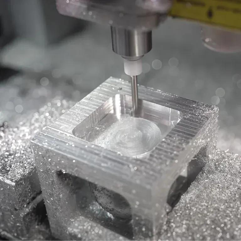
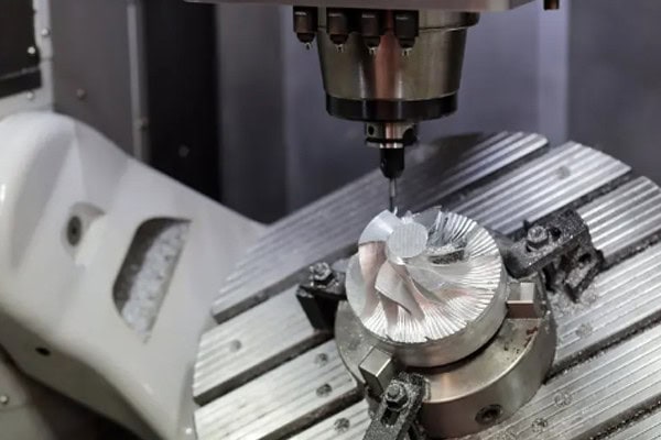
The pump cavity directly affects the installation space for internal components. Machining cannot focus only on one depth or internal diameter; the dimensional relationship throughout the cavity also needs to remain consistent. For deep or structurally complex cavities, proper tool selection, toolpaths, and cutting parameters can help reduce vibration and improve dimensional stability during finishing.
- Control internal cavity dimensions: The cavity diameter, depth, and transition areas need to meet drawing requirements to prevent interference or excessive clearance during assembly.
- Reduce machining vibration: Deep cavities often require longer tool overhangs, so cutting parameters need to be adjusted to prevent chatter marks and poor surface quality.
- Leave suitable machining allowance: Rough machining should not immediately reach the final dimension. A controlled allowance should be left for stable finishing operations.
After the pump cavity is machined, critical dimensions still need to be inspected rather than relying on visual checks alone. For batch production, maintaining a stable machining condition is even more important, since gradual dimensional changes across the same batch can create problems during assembly.
Accurate Positioning of Shaft and Mounting Holes
Pump bodies may contain many holes, but their functional importance is not always the same. Shaft holes, locating holes, and mounting holes can directly affect the installation of internal components or external structures. Their diameters, spacing, and positional relationships all need to remain consistent.
- Shaft hole machining: Hole diameter, roundness, and its positional relationship with the relevant datum need to be carefully controlled.
- Mounting hole machining: Hole spacing and distribution must match the installation requirements of the mating equipment to prevent misalignment during assembly.
- Locating hole machining: Locating features need good repeatability to support component installation and future maintenance.
- Threaded hole machining: Thread size, depth, and effective thread length need to meet drawing requirements to ensure reliable fastening.
For these critical holes, CNC machining stability directly affects final assembly. When the same pump body is produced continuously, it is not enough to make the first part correctly. Subsequent parts need to maintain a similar machining condition as well.
Sealing Surface Machining Affects Real-World Performance
Industrial pump bodies often work with sealing rings, gaskets, or other sealing components. Noticeable tool marks, flatness deviations, or localized deformation on sealing surfaces may cause leakage after assembly. These areas need to be treated as critical machining zones, with finishing operations properly planned and surface conditions and key dimensions verified during final inspection.
| Critical Pump Body Area | CNC Machining Focus | Impact on Assembly |
| Pump cavity | Diameter, depth, surface quality | Affects internal component installation |
| Shaft hole | Diameter, positional accuracy, roundness | Affects shaft fit |
| Sealing surface | Flatness, surface roughness, dimensions | Affects sealing performance |
| Flange surface | Flatness, hole spacing | Affects pipe connection |
| Threaded holes | Thread specification, depth | Affects fastening |
How Should Different Materials Be CNC Machined for Industrial Pump Bodies?
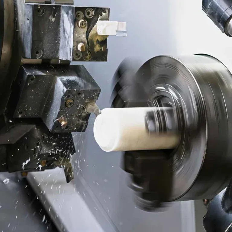
Industrial pump bodies can be manufactured from different materials, and each material has different requirements for tooling, cutting speed, cooling, and machining strategy. Aluminum alloys are relatively easy to cut but require attention to burrs and surface quality. Stainless steel has higher toughness and can experience work hardening during machining. Cast iron requires effective chip and dust management. Once the material is selected, the machining process should be adjusted accordingly rather than applying the same parameters to every material.
Aluminum Alloy Pump Bodies
Aluminum alloy pump bodies are widely used because they are lightweight and generally efficient to machine. However, machining can generate burrs, while thin-wall structures may be susceptible to deformation.
- Keep cutting tools sharp: This helps reduce burr formation caused by material deformation during cutting.
- Control cutting forces on thin-wall areas: Excessive cutting force can cause dimensional changes after machining.
- Pay attention to surface quality during finishing: Critical areas such as the pump cavity and mounting surfaces should receive suitable finishing treatment.
Stainless Steel Pump Bodies
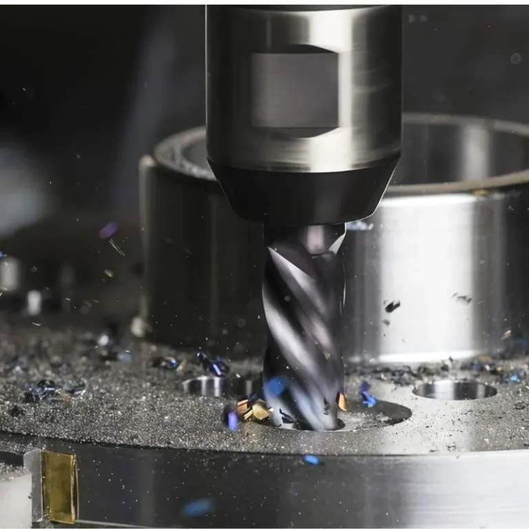
Stainless steel offers good corrosion resistance and is commonly used in industrial equipment exposed to demanding operating environments. However, it can generate significant heat and work hardening during machining, while tool wear may also increase. Production therefore requires closer attention to tool condition and cutting parameters.
Cast Iron and Other Alloy Pump Bodies
Cast iron can generate a large amount of fine chips during machining, making machine cleanliness and cooling management important. High-strength or corrosion-resistant alloys may also place greater demands on tool life. Adjusting the machining strategy for each material can help reduce abnormal tool wear and maintain dimensional consistency during batch production.
How Can CNC Machining Maintain Batch Consistency for Industrial Pump Bodies?
A successful prototype does not automatically mean that batch production will remain stable. Once industrial equipment customers move into long-term purchasing, they are more concerned about whether parts from different production batches remain consistent. Tool wear, changes in machine condition, and material batch variations can all cause small dimensional changes. Clear inspection points should be established during production rather than leaving all inspection work until the final stage.
What Needs to Be Confirmed Before Machining?
Before production begins, the drawing, tolerances, material, and surface requirements need to be clearly confirmed, especially for critical areas such as the pump cavity, shaft holes, and sealing surfaces. For structurally complex components, the clamping method and machining datum should also be confirmed in advance to reduce the need for temporary process changes during production.
- Confirm the drawing revision: Avoid using outdated and current drawings at the same time, particularly when dimensions, tolerances, or hole positions have been modified.
- Confirm material specifications: The material grade and condition should meet the order requirements to avoid unexpected machining performance.
- Confirm critical dimensions: Mark key assembly-related dimensions in advance so that production and inspection personnel can pay closer attention to them.
- Confirm surface treatment requirements: If anodizing, passivation, painting, or other processes are required, suitable machining allowance should be considered in advance.
Inspection During Production Is Essential
For industrial pump bodies, in-process inspection helps identify dimensional changes at an early stage. After first-piece approval, sampling inspections can be arranged based on order quantity and component structure, with critical dimensions continuously monitored. If tool wear or machine condition changes are detected, adjustments can be made earlier instead of discovering the issue after an entire batch has been completed.
Final Inspection Should Go Beyond Appearance
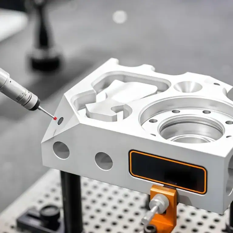
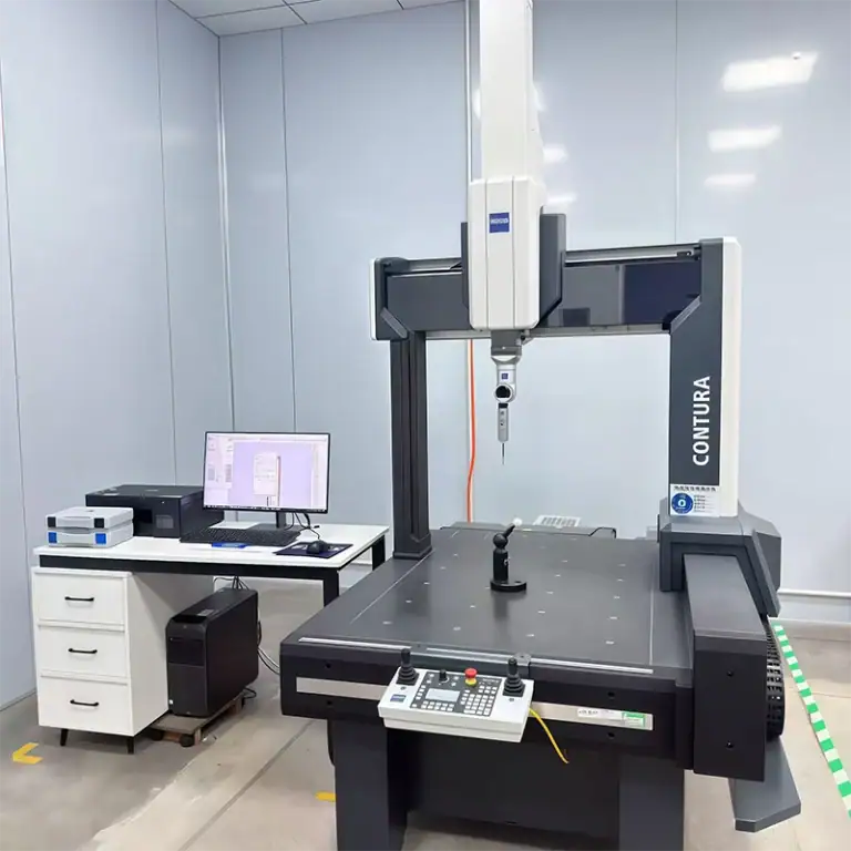
Final inspection needs to follow the customer’s drawing requirements rather than simply checking the part for visible scratches, dents, or burrs. Critical hole diameters, hole spacing, sealing surfaces, mounting datums, and threaded areas should all be inspected according to their specified requirements. When specific inspection documentation is required, dimensional records can also be prepared to give buyers a clearer understanding of the finished part’s condition.
How Should You Choose a CNC Machining Supplier for Industrial Pump Bodies?
Industrial pump body procurement often involves several stages, including prototyping, trial assembly, design modifications, and batch production. If a supplier can only handle one-time machining, problems may arise when drawings change or order volumes increase. When evaluating a supplier, it is useful to focus on actual machining capabilities, quality control, and project coordination, as these factors provide a clearer picture of whether the supplier can support long-term production.
Evaluate Actual Machining Capabilities
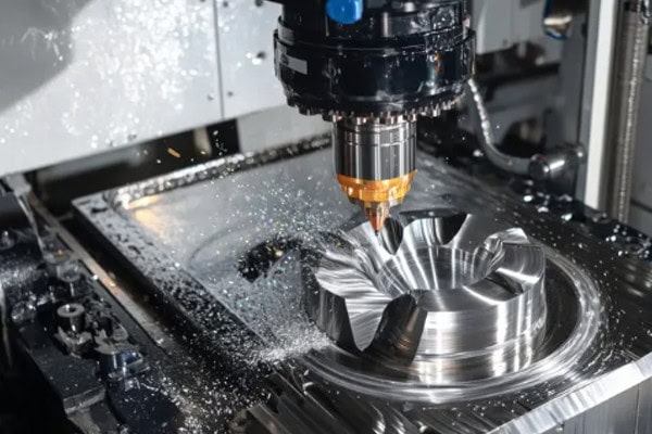
Having suitable CNC equipment is only the starting point. More important is whether the supplier has experience machining complex pump body structures. Buyers can review machine capabilities, machining methods, inspection equipment, and previous industrial equipment components to make sure the supplier’s capabilities match the actual part requirements.
Check Whether the Quality Control Process Is Clear
- First-piece inspection: Verify sample dimensions and critical structures before starting batch production.
- In-process inspection: Monitor key dimensions during machining to reduce batch variation.
- Final inspection: Check critical dimensions, appearance, and drawing requirements before delivery.
- Inspection records: Maintain necessary dimensional records for future traceability and order review.
Reliable CNC machining is not simply about achieving the correct dimension once. It is about maintaining controlled variation throughout continuous production. For industrial equipment manufacturers, this consistency can directly affect assembly efficiency while reducing rework and on-site adjustments.
Check Whether Prototyping Can Transition Smoothly Into Mass Production
New pump body projects often begin with prototypes for assembly testing. During testing, hole positions, dimensions, or local structures may need to be modified. The supplier needs to understand these changes quickly and carry the validated process into subsequent batch production, avoiding major differences between prototype and mass-produced parts.
Industrial pump body CNC machining ultimately needs to connect precision, assembly performance, and long-term production stability. Stable pump cavity dimensions, accurate shaft hole positioning, reliable sealing surfaces, suitable material processing, and proper inspection all contribute to components that perform effectively in industrial equipment. For customers requiring industrial pump body prototyping, custom machining, or batch production, TIRAPID provides professional CNC machining services from drawing communication through final delivery, helping create a more stable machining process and smoother project execution.