During product development, metal prototype parts play an important role in validating structural designs, assembly accuracy, and functional performance. Whether developing automation equipment, robotics, automotive components, or industrial machinery, choosing the right metal manufacturing method can help shorten development cycles, control prototyping costs, and reduce risks before mass production. When comparing CNC machining, sheet metal fabrication, and metal 3D printing, manufacturers should consider part geometry, material requirements, dimensional tolerances, and order quantities to determine the most suitable rapid manufacturing solution.
Get 20% offf
Your First Order
Need custom metal and plastic parts?
What Are the Common Manufacturing Methods for Metal Prototype Parts?
CNC Machining: Ideal for High-Precision Functional Prototypes
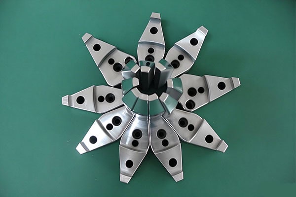
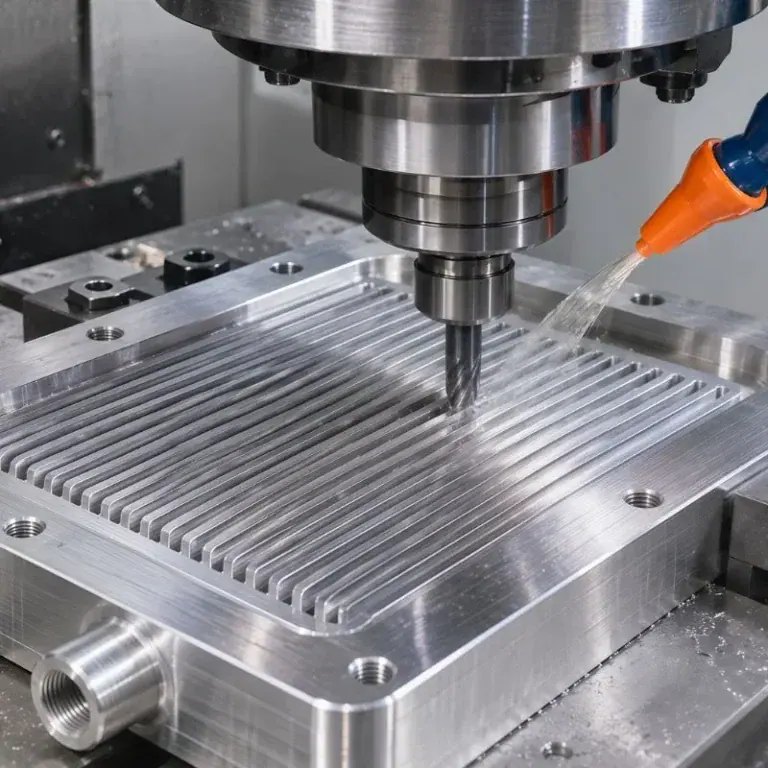
CNC machining uses computer-controlled cutting tools to remove material through milling, turning, drilling, and other operations. It produces metal parts with accurate dimensions and consistent structural quality. CNC machining is often a preferred option for prototypes that require assembly testing, mechanical movement testing, or load validation.
Aluminum alloys are lightweight and easy to machine, making them suitable for robot brackets, equipment housings, and mounting plates. Stainless steel is appropriate for components requiring high strength and corrosion resistance, while brass is commonly used for connectors, valve components, and precision mechanical parts.
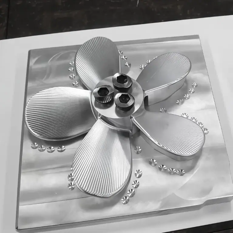
Depending on part geometry, manufacturers can choose three-axis, four-axis, or five-axis CNC machining. Three-axis machining is suitable for relatively simple components, while five-axis machining can handle complex surfaces, multi-angle features, and parts requiring machining on multiple sides. It can also reduce errors caused by repeated setups.
Sheet Metal Fabrication: Ideal for Thin-Walled Structures and Metal Enclosures
When a prototype primarily consists of thin metal sheets, sheet metal fabrication is often a practical solution. Laser cutting, bending, welding, and assembly can be combined to manufacture equipment cabinets, protective covers, brackets, and control enclosures.
Sheet metal fabrication is suitable for validating external dimensions, mounting positions, and overall structural layouts. However, if a product requires complex three-dimensional surfaces, precision holes, or high-accuracy mating features, additional CNC finishing may be necessary.
Metal 3D Printing: Suitable for Complex Internal Structures
Metal 3D printing builds components layer by layer, enabling the production of complex geometries that are difficult to manufacture using conventional cutting tools. Examples include internal channels, specialized lattice structures, and certain lightweight designs.
This process is useful for exploring new geometries and developing specialized functional prototypes. However, equipment costs, material expenses, post-processing requirements, and dimensional accuracy must all be considered. For simple metal components with strict cost requirements, CNC machining or sheet metal fabrication may be more economical.
How Do You Choose a Manufacturing Method Based on Project Requirements?
Select the Process According to Precision and Functional Requirements
If a prototype must fit with bearings, threaded holes, linear guides, or other mechanical components, dimensional tolerances, hole positioning, and surface roughness become critical considerations. CNC machining is well suited to these functional validation requirements.
If a part is primarily intended for visual presentation or basic spatial layout verification, some non-critical dimensional requirements may be relaxed to avoid unnecessary precision machining costs.
Consider Material Properties and Part Geometry
The manufacturing method should match the characteristics of the selected material. Aluminum alloys are suitable for lightweight structural components, stainless steel is useful in corrosion-resistant applications, and steel is appropriate for mechanical components requiring higher strength.
For thin-walled parts, deep cavities, slender structures, or complex surfaces, manufacturers should also evaluate tool accessibility, machining deformation, and fixture stability. Adjusting corner radii, wall thicknesses, and machining datums where appropriate can improve manufacturing efficiency.
Choose According to Prototype Quantity and Delivery Schedule
Single-piece and low-volume prototypes generally do not require dedicated tooling at the initial development stage. CNC machining can produce components directly from CAD models and engineering drawings, making it suitable for design validation and small-batch prototyping.
When a product moves into stable, high-volume production, manufacturers should reassess whether stamping, casting, or other scalable manufacturing processes are more economical. For products with complex geometries and demanding precision requirements that are still undergoing design iterations, rapid CNC prototyping followed by manufacturing process optimization can help reduce development risks.
How Can You Improve the Manufacturing Efficiency of Metal Prototype Parts?
Conduct Design for Manufacturability (DFM) Analysis Before Machining
Design for Manufacturability (DFM) analysis helps identify potential manufacturing challenges before production begins. Engineers review dimensional tolerances, wall thicknesses, internal corner radii, hole depths, threads, and surface finishing requirements, then recommend appropriate design improvements.
Well-planned design adjustments can reduce complex setups, repeated machining operations, and material waste while preserving the required functionality and performance of the component.
Provide Complete Design Files
To accelerate quotation and production preparation, customers should provide three-dimensional CAD files in STEP or STP format, together with two-dimensional engineering drawings that specify critical dimensions, tolerances, materials, and surface finishing requirements.
For prototypes intended for assembly validation, customers should also identify mating components, critical interfaces, and testing objectives. More complete information helps the manufacturing team establish an appropriate process plan and reduces delays caused by repeated clarification.
Integrate Quality Inspection into the Rapid Manufacturing Process
Rapid manufacturing should never come at the expense of quality control. Raw material verification, in-process inspection, and final dimensional checks help identify problems early. Depending on the component and its precision requirements, suitable inspection equipment may include coordinate measuring machines (CMMs), optical measuring projectors, and other dimensional measurement tools.
How Does TiRapid Support Rapid Manufacturing of Metal Prototype Parts?
TiRapid provides custom metal CNC machining services for materials such as aluminum alloys, stainless steel, steel, and brass. Its capabilities include three-axis, four-axis, and five-axis CNC machining, as well as large-part machining. The company supports rapid prototyping, low-volume production, and subsequent manufacturing requirements, with solutions tailored to part drawings, material specifications, and precision requirements.
TiRapid also offers engineering support and DFM optimization to help customers evaluate manufacturability before production. For projects involving metal enclosures, plastic components, or other structural parts, complementary manufacturing services such as sheet metal fabrication, injection molding, and aluminum extrusion can help coordinate different component production requirements.
Rapid manufacturing of metal prototype parts should be driven by the actual validation objectives rather than speed alone. By selecting the appropriate process—CNC machining, sheet metal fabrication, or metal 3D printing—and combining it with design optimization, material evaluation, and quality inspection, businesses can validate products more efficiently and establish a reliable foundation for subsequent low-volume production and large-scale manufacturing.
For projects requiring rapid prototyping, TiRapid can evaluate manufacturing feasibility based on three-dimensional models and engineering drawings, helping customers clarify material selection, precision requirements, processing methods, and delivery arrangements.
Author
Galen Director and Founder
Committed to ensuring we provide the best possible service in the manufacturing industry.
Aerospace machining services manufacture precision components for aircraft, spacecraft, propulsion systems, hydraulic equipment, avionics, and other demanding applications. These parts often combine lightweight geometry, tight dimensional relationships, difficult materials, and
5 axis aerospace machining is used to produce complex aircraft and spacecraft components that are difficult to manufacture with conventional 3-axis equipment. By controlling 3 linear axes and two rotary
Aerospace CNC machining is used to manufacture lightweight, complex, and dimensionally controlled components for aircraft, spacecraft, propulsion systems, hydraulic equipment, and avionics assemblies. These parts often combine thin walls, deep
Propeller machining is the process of manufacturing or finishing propeller blades, hubs, shafts, and mounting features to meet specified dimensions and surface requirements. Because propeller blades contain twisted profiles, variable
Wafer handle systems move semiconductor wafers between carriers, aligners, inspection stations, process tools, load locks, and vacuum modules while maintaining controlled position and minimizing physical contact. Because wafers are thin
UAV parts are the structural, mechanical, electrical, and electronic components that allow an unmanned aerial vehicle to fly, navigate, communicate, and carry payloads. Common drone components include frames, motors, propellers,
An intake manifold connects an engine’s air supply to its intake ports. Its internal passages, mounting interfaces, and connections must work with the engine as a complete system. A standard
Vacuum chambers are precision enclosures designed to create and maintain controlled low-pressure environments for semiconductor manufacturing, research equipment, coating systems, testing platforms, and other vacuum-dependent processes. Their performance depends on
An aluminum water cooling block is a liquid cooling component that transfers heat from electronic devices into circulating coolant. Compared with copper alternatives, aluminum offers lower weight, competitive material costs,
A micro channel cold plate is a precision liquid cooling component that removes heat from high-power electronics through closely spaced internal fluid channels. These channels increase the contact area between
Semiconductor vacuum components are precision parts used to create, maintain, control, and isolate low-pressure environments inside semiconductor manufacturing equipment. Vacuum chambers, flanges, valve bodies, manifolds, chucks, ports, and wafer-handling parts
A part does not have to be small enough to fit on a fingertip to require micromachining. A larger component may contain a tiny hole, narrow channel, or thin wall