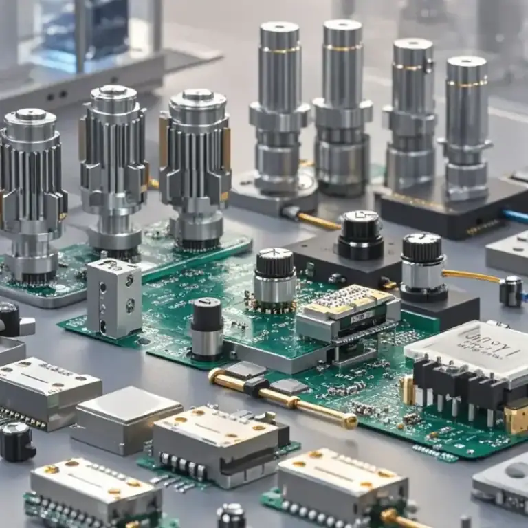
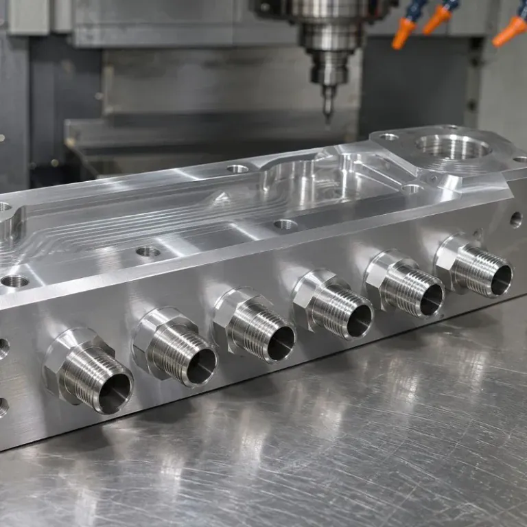
As chips become smaller and more highly integrated, traditional packaging methods are no longer sufficient for some high-performance applications. 3D IC packaging improves integration by stacking chips vertically and shortening interconnection distances, but it also creates new manufacturing challenges for packaging equipment. These machines need to perform precise die bonding, wafer handling, and thermocompression bonding. Their internal components must not only meet tight dimensional tolerances but also withstand temperature changes and mechanical loads during continuous operation. A poorly machined structural component can affect the performance of an entire machine. With a suitable CNC machining solution, complex parts can better meet equipment assembly and operating requirements.
Which Parts of 3D IC Packaging Equipment Require Precision Machining?
3D IC packaging equipment is not a single mechanical structure. It consists of different modules for wafer handling, die bonding, bonding processes, inspection, and material transfer. Each module uses different components. Some parts support wafers, others work with motion systems to achieve accurate positioning, while certain components must remain stable under changing temperatures. Machining processes should be selected according to the actual function of each part rather than its external shape alone.
Mechanical Components in Wafer Handling Systems
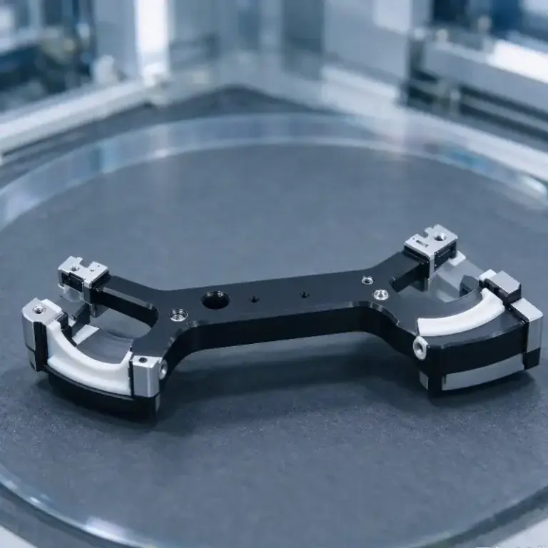
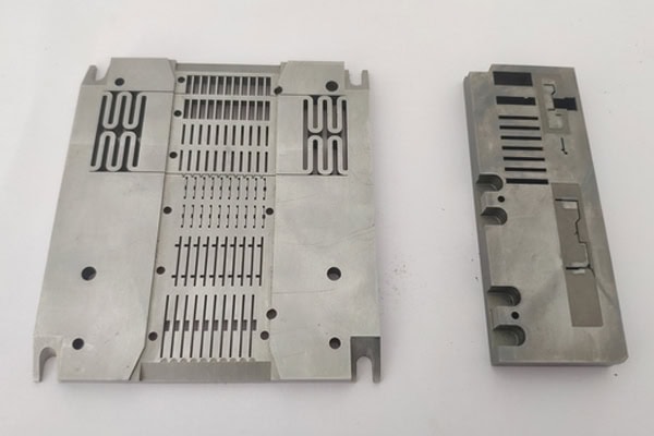
During wafer transfer between different processing stages, robotic arms, transfer brackets, and connecting bases work together to move wafers. These components are generally designed to be lightweight and compact, with accurate mounting holes, connection surfaces, and motion interfaces. If the weight distribution is unsuitable or connection positions are inaccurate, the transfer mechanism may not operate smoothly.
Support Structures for Die Bonding and Bonding Equipment
Die bonding and bonding equipment require stable mechanical support. Some structures also work with precision motion platforms to perform vertical movement and positional adjustments. Machining must focus on mounting surface flatness, hole positioning, and structural rigidity. For support components used over long operating periods, dimensional stability under load is also important to minimize positioning changes during machine operation.
Key Components and Machining Requirements for 3D IC Packaging Equipment
Different equipment modules have different component requirements. The following table lists several common parts and their main machining considerations.
| Component | Equipment Module | Main Machining Requirements |
| Wafer transfer bracket | Wafer handling system | Lightweight structure, mounting hole accuracy |
| Die bonding base | Die bonding equipment | Flatness, positioning dimensions |
| Bonding equipment connection plate | Thermocompression bonding system | Hole spacing, structural rigidity |
| Precision motion connector | Positioning mechanism | Fitting dimensions, positional accuracy |
| Vacuum interface component | Wafer suction system | Sealing surfaces, interface dimensions |
Why Do Dimensional Deviations Occur During 3D IC Packaging Equipment Parts Machining?
The machining challenges of these components are often hidden in small features and complex assembly relationships. Some parts require multiple holes, threads, and mounting slots within limited spaces. Others must maintain strict flatness requirements. Even when individual dimensions appear acceptable, positional deviations between different features can still affect the final assembly.
Complex Structures Make Machining Sequence Important
Some equipment components have stepped surfaces, grooves, deep cavities, and side holes. If the machining sequence is poorly planned, cutting tools may have difficulty reaching certain areas during later operations, or additional setups may be required. Repeated positioning can accumulate errors, especially for components with strict positional relationships between multiple surfaces. Planning the machining route in advance and establishing consistent reference datums can reduce unnecessary process changes.
Temperature Changes Can Affect Precision Component Dimensions
Certain components inside 3D IC packaging equipment operate in heated or temperature-controlled environments. Materials expand when heated, and different materials have different thermal expansion characteristics. If the dimensions of support parts, connectors, and mounting bases are not properly matched, long-term operation may affect equipment positioning. Machining solutions should consider material properties and actual operating temperatures rather than relying only on room-temperature dimensions.
Key Details to Control During CNC Machining
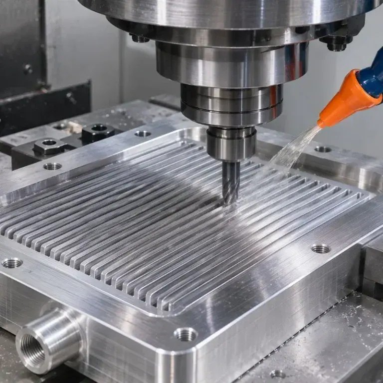
The quality of precision equipment components depends not only on machine accuracy but also on tool condition, cutting methods, and subsequent finishing processes. The following details deserve particular attention during production:
- Complex grooves: Control groove width, depth, and edge quality to prevent dimensional deviations.
- Threaded connections: Maintain accurate thread specifications and effective thread depth for smooth installation.
- Thin-wall sections: Arrange cutting sequences carefully to reduce local deformation.
- Positioning holes: Check hole spacing and positional relationships to ensure proper module assembly.
How Should Materials and CNC Machining Methods Be Selected for 3D IC Packaging Components?
Material selection should consider more than strength. Weight, thermal conductivity, corrosion resistance, and long-term dimensional stability also matter. For example, motion systems benefit from reduced component weight, support structures need sufficient rigidity, and certain thermocompression bonding components must withstand temperature changes. Different applications require different materials, and CNC machining methods should be adjusted accordingly.
Which Materials Are Commonly Used for 3D IC Packaging Equipment Parts?
Aluminum alloys are suitable for certain lightweight structural components and offer good machinability. Stainless steel is commonly used for connecting components that require corrosion resistance and strength, while copper alloys can be selected for parts that require good thermal conductivity. Material selection should also account for subsequent surface treatments and potential dimensional changes after machining.
| Material | Main Properties | Typical Applications |
| 6061 Aluminum Alloy | Lightweight, good machinability | Transfer brackets, equipment bases |
| 7075 Aluminum Alloy | High strength | Precision connectors, load-bearing structures |
| 304 Stainless Steel | Good corrosion resistance | Connecting parts, fixing components |
| 316 Stainless Steel | Enhanced corrosion resistance | Structural components for demanding environments |
| Copper Alloy | Good thermal conductivity | Heat-conducting components, thermal management parts |
Multi-Axis CNC Machining for Complex Packaging Components
For components with holes, angled surfaces, and recessed features on multiple sides, multi-axis CNC machining can complete more features in a single setup. This reduces positioning errors caused by repeated clamping. If a component has a relatively simple structure, three-axis milling or CNC turning may also meet its machining requirements. The key is to select processes according to the geometry shown in the drawings and avoid unnecessary machining complexity that increases production costs.
Proper Coordination Between Finishing and Surface Treatment
Some packaging equipment components require anodizing, passivation, or other surface treatments after machining. It is important to remember that surface treatments may change the final dimensions of a part, particularly around precision fitting holes, mounting surfaces, and threaded areas. For components with tight tolerances, machining allowances should be planned in advance, and critical dimensions should be inspected after treatment. This helps prevent interference or incorrect clearances during assembly.
How Can 3D IC Packaging Equipment Parts Be Made More Suitable for Actual Assembly?
After precision machining, the real test is whether a component can be installed correctly and maintain stable performance during continuous operation. Some parts may pass individual dimensional inspections but still cause interference, uneven clearances, or positioning problems when assembled with other components. Assembly relationships must therefore be considered during machining rather than focusing only on the dimensions of individual parts.
Establish Machining Datums Based on Equipment Assembly Requirements
For components connected to motion platforms, robotic arms, or bonding modules, the mounting and positioning datums should be clearly defined. Using consistent reference surfaces during machining helps prevent positional errors caused by different setups. If a component needs to fit existing equipment, connection hole spacing, mounting height, and interface dimensions should also be checked in advance to reduce on-site modifications.
Arrange Inspection Items According to Component Functions
Different components require different inspection priorities. Wafer support structures need close attention to flatness and surface quality, while motion connectors require accurate hole positions, fitting dimensions, and positional tolerances. Inspection can be performed using coordinate measuring machines and precision measuring instruments, with critical dimensions recorded for quality tracking.
Common inspection items include:
- Distance and positional deviations between mounting holes
- Flatness and perpendicularity of connection surfaces
- Dimensional tolerances of precision fitting areas
- Surface defects such as burrs, scratches, and machining residue
- Compliance of critical features with assembly drawing requirements
Identify Potential Problems Through Trial Assembly
For components with complex structures and close assembly relationships, trial assembly can reveal problems that individual dimensional inspections may not detect. For example, two connecting parts may each meet their dimensional requirements, yet still be difficult to install when assembled together. Checking the actual fit helps verify positioning relationships, installation clearances, and connection structures. For components that will be manufactured repeatedly, any issues found during trial assembly can be fed back into the machining process to improve consistency in subsequent production batches.
Precision manufacturing for 3D IC packaging equipment requires more than accurate dimensions. Material properties, operating environments, and overall assembly relationships must also be considered. Whether manufacturing wafer transfer brackets, die bonding bases, or bonding equipment connectors, the machining process should match the actual equipment structure and application. TIRAPID provides precision CNC machining services for semiconductor equipment and can develop custom machining solutions based on engineering drawings, material requirements, and tolerance specifications. Contact us to discuss your 3D IC packaging equipment parts machining needs.