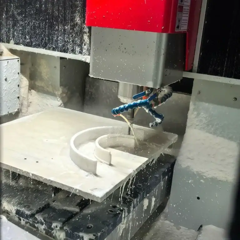
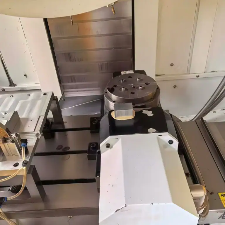
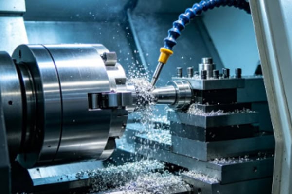
Tool wear is a very common issue during turning operations. Whether using a conventional lathe or a CNC lathe, cutting tools gradually wear out under continuous machining conditions. Once tool wear becomes severe, it can affect dimensional accuracy, surface finish, machining efficiency, and may even cause tool breakage or workpiece scrap. In many machining workshops, problems such as unstable dimensions, frequent insert failure, and abnormal cutting noise are closely related to tool wear. Identifying tool wear conditions in time and applying proper solutions can significantly improve machining stability and extend tool life.
Why Does Turning Tool Wear Occur?
During turning operations, the cutting tool is exposed to high temperature, pressure, and constant friction. Tool wear is therefore unavoidable. However, the wear rate varies greatly depending on machining conditions. Understanding the causes of wear helps reduce tool damage more effectively.
Excessive Cutting Temperature Causes Tool Damage
During turning, a large amount of heat is generated near the cutting edge. The higher the cutting speed, the stronger the friction between the tool and the workpiece, causing the tool tip temperature to rise rapidly. When the temperature remains too high, tool hardness decreases, the cutting edge softens, and coating peeling or edge chipping may occur. This issue becomes more serious during high-speed machining of stainless steel and hardened materials. If cooling conditions are insufficient, tool life will decrease significantly.
Workpiece Hardness Affects Tool Life
Different materials affect tool wear at different rates:
- Mild steel is relatively easy to machine
- Hardened steel generates higher cutting resistance
- Stainless steel tends to cause built-up edge and work hardening
- Cast iron produces abrasive wear particles
If the insert material does not match the workpiece material, rapid tool wear or edge chipping can easily occur.
Improper Cutting Parameters
Many tool failures are related to incorrect parameter settings. Excessive cutting speed, feed rate, or cutting depth increases tool load significantly. Once cutting parameters exceed the insert’s capacity, cutting temperature rises rapidly and wear accelerates. Some operators use heavy cutting conditions continuously to improve productivity, but this often shortens insert life considerably.
Common Types of Turning Tool Wear
Different wear patterns affect machining quality and tool life in different ways. Understanding common wear types helps operators identify problems and adjust machining conditions quickly.
Flank Wear
Flank wear is one of the most common forms of tool wear. As cutting time increases, the flank surface gradually wears down, causing the cutting edge to become dull. This leads to reduced surface finish quality and increased cutting resistance. Continued use may result in dimensional inaccuracies. Under normal conditions, flank wear is expected, but inserts should be replaced once wear reaches a critical limit.
Crater Wear on the Rake Face
Continuous chip flow over the rake face under high temperature gradually forms a crater-shaped groove. This type of wear is common during high-speed machining, especially when processing high-strength materials. Crater wear weakens the insert structure and may eventually cause edge failure. In high-speed cutting environments, improper parameter control can accelerate crater wear dramatically.
Edge Chipping Problems
Edge chipping is a serious tool failure issue. Common causes include:
- Excessive cutting impact
- Severe machine vibration
- Poor workpiece clamping stability
- Insufficient tool strength
This issue is more likely to occur during interrupted cutting. Once the cutting edge chips, visible marks often appear on the workpiece surface, and dimensional accuracy may be affected immediately.
How to Reduce Turning Tool Wear
Although tool wear cannot be completely avoided, proper machining adjustments can significantly reduce wear rates. In many production environments, insert life improves greatly after optimizing machining conditions.
Select Proper Tool Materials
Different workpiece materials require different insert types:
- General steel machining uses coated carbide inserts
- Stainless steel requires heat-resistant inserts
- Hardened materials require CBN tools
- Aluminum alloys are better suited for PCD inserts
When the insert material is properly matched, machining stability and tool life improve significantly.
Adjust Cutting Parameters to Reduce Load
Reasonable cutting parameters help reduce tool stress. If tool wear occurs too quickly, cutting speed can be reduced, feed rate lowered, or multi-pass cutting methods adopted. In many cases, slightly reducing spindle speed can noticeably extend insert life. Machining parameters should also be adjusted continuously according to actual cutting conditions rather than remaining fixed.
Improve Cooling and Chip Evacuation
Coolant reduces tool tip temperature and improves chip evacuation. If coolant flow is insufficient or directed improperly, heat cannot be removed effectively, accelerating tool wear. Poor chip evacuation may also cause chips to rub repeatedly against the insert, increasing cutting temperature further. Using chip breaker inserts, increasing coolant pressure, and optimizing machining paths can all improve chip control.
How to Determine When a Tool Should Be Replaced
Many operators continue using inserts even after severe wear occurs. This not only affects machining quality but also increases production risks. Proper tool condition monitoring helps avoid further machining problems.
Surface Finish Quality Declines Noticeably
As the cutting edge becomes dull, the workpiece surface begins to change noticeably. Common signs include rough surfaces, excessive tool marks, surface tearing, and reduced smoothness. These symptoms usually indicate that the insert has entered a severe wear stage. Continued machining may result in product rejection.
Dimensional Accuracy Becomes Unstable
After tool wear develops, machining repeatability decreases:
- Dimensions begin drifting
- Product consistency worsens
- Finishing accuracy decreases significantly
- Tool compensation adjustments become more frequent
Even if the machine and program remain unchanged, unstable dimensions are often caused by worn tools.
Abnormal Cutting Noise and Machine Load
Under normal conditions, cutting sound remains relatively stable. If sharp noise, high-frequency vibration, or repeated impact sounds appear during machining, abnormal tool wear is often the cause. At the same time, spindle load usually increases, along with stronger machine vibration and heat generation. Continued use of worn tools may lead to insert breakage or even machine damage.
Common Mistakes in Turning Tool Usage
Many machining workshops have incorrect operating habits that may not show immediate problems but will gradually accelerate tool wear and affect machine stability.
Common issues include continuous heavy-load cutting, failing to change inserts for different materials, continuing to use severely worn tools, and keeping cutting parameters unchanged for long periods. Some operators also ignore coolant concentration and chip evacuation conditions, causing tools to remain under excessive heat. Different materials, workpiece structures, and machining stages all require flexible adjustment of tools and cutting conditions. Using the same parameters and inserts continuously often results in increasingly severe tool wear problems.