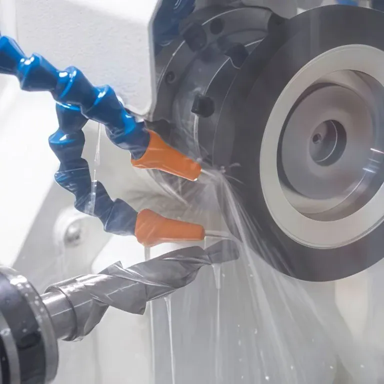
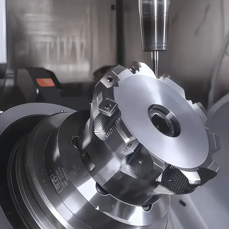
Grinding is a precision machining process that removes material from a workpiece using a rotating abrasive wheel. Unlike conventional cutting tools, which remove material with defined cutting edges, grinding uses many abrasive grains to remove small amounts of material. This process is widely used to improve dimensional accuracy, produce smooth surfaces, and finish hardened or difficult-to-machine components.
This guide explains what grinding is, how the grinding process works, the main types of grinding, machines, materials, technical parameters, advantages, limitations, and common CNC applications.
What Is Grinding?
Grinding is an abrasive machining process that removes small amounts of material from a workpiece using a rotating grinding wheel. It is mainly used to achieve accurate dimensions, controlled geometry, and fine surface finishes. In precision manufacturing, grinding is commonly performed after CNC milling, turning, or heat treatment when the part requires tighter tolerances or improved surface quality.
Grinding vs. CNC Milling and Turning
Grinding differs from CNC milling and turning mainly in its cutting mechanism, material removal rate, and finishing purpose. Milling and turning are generally efficient for creating part geometry and removing larger volumes of material, while grinding is often used for fine dimensional correction and surface finishing.
| Feature | Grinding | CNC Milling | CNC Turning |
| Cutting tool | Abrasive wheel | Rotating milling cutter | Single-point or multi-edge tool |
| Material removal | Usually small, controlled amounts | Moderate to high | Moderate to high |
| Typical geometry | Flat, cylindrical, internal, profile | Pockets, slots, contours | Shafts, bores, round parts |
| Main advantage | High accuracy and fine finish | Complex shape generation | Efficient cylindrical machining |
| Hardened materials | Often suitable | Requires appropriate tooling | Requires appropriate tooling |
| Typical production role | Precision finishing | Roughing and finishing | Roughing and finishing |
Grinding is therefore best understood as a complementary manufacturing process rather than a universal replacement for CNC cutting.
How Does the Grinding Process Work?
The grinding process works by selecting a suitable abrasive wheel, securing the workpiece, setting grinding parameters, removing material through controlled wheel contact, managing heat, and inspecting the final dimensions and surface finish. Each stage must be controlled because wheel condition, cutting force, temperature, and machine stability directly affect grinding accuracy.
| Step | Grinding Operation | Quality Objective |
| 1 | Select wheel and parameters | Match abrasives to material |
| 2 | Mount and align workpiece | Prevent movement and distortion |
| 3 | Perform grinding passes | Remove controlled finishing stock |
| 4 | Control heat and coolant | Prevent thermal damage |
| 5 | Measure and inspect | Verify size, geometry, and finish |
Step 1: Select the Grinding Wheel and Set Cutting Parameters
The first step is selecting a grinding wheel suitable for the workpiece material, required accuracy, surface finish, and removal rate. Wheel abrasive, grit size, bond, hardness grade, and structure all affect cutting performance.
An aluminum oxide wheel may be appropriate for many steels, while CBN wheels are often preferred for hardened ferrous materials. Diamond wheels are commonly selected for carbide and ceramics. The machine settings must also remain within the wheel’s approved operating speed and match the intended grinding operation.
Step 2: Set Up and Secure the Workpiece
The workpiece must be supported and positioned accurately before grinding begins. Surface grinding commonly uses magnetic chucks for suitable ferrous materials, while nonmagnetic workpieces may require mechanical fixtures or vacuum workholding. Cylindrical grinding may use centers, chucks, or centerless support.
Clamping must be secure without introducing deformation. Thin plates, long shafts, and precision components can bend under excessive holding force. If a part is ground while distorted, it may change shape after release and fail flatness, roundness, or dimensional requirements.
Step 3: Start Grinding and Control Material Removal
During grinding, the abrasive wheel contacts the workpiece and removes material through repeated cutting passes or controlled infeed. Wheel speed, table movement, workpiece rotation, and depth of cut determine material removal behavior.
Grinding operations usually require smaller cuts than rough milling or turning, particularly during precision finishing. A suitable finishing allowance must remain from the previous operation. Removing excessive stock during final grinding can increase heat, wheel wear, and dimensional variation.
Step 4: Apply Coolant and Control Grinding Heat
Coolant controls grinding temperature, lubricates the contact area where appropriate, and helps remove abrasive debris and metal particles. Heat control is essential because excessive temperature can cause thermal expansion, surface burns, residual stress, and dimensional changes.
Coolant must reach the actual grinding contact zone. Simply increasing fluid volume may not solve a problem if wheel rotation prevents coolant from entering the interface. Proper nozzle position, fluid condition, filtration, and wheel selection help maintain stable grinding performance.
Step 5: Inspect Dimensions and Surface Finish
The final step is checking whether the ground part meets its dimensional and surface requirements. Inspection may include thickness, diameter, roundness, flatness, parallelism, surface roughness, and other drawing specifications.
Micrometers, bore gauges, height gauges, surface roughness testers, and coordinate measuring machines may be used depending on the feature. Parts requiring very tight tolerances should be measured under controlled temperature conditions, since thermal expansion can affect micron-level inspection.
What Machines and Equipment Are Used for Grinding?
Grinding uses specialized equipment including surface grinders, cylindrical grinders, centerless grinders, internal grinders, CNC grinding machines, abrasive wheels, workholding fixtures, wheel dressing devices, and coolant systems. The correct grinding machine is selected according to part geometry, material, tolerance, required finish, and production quantity.
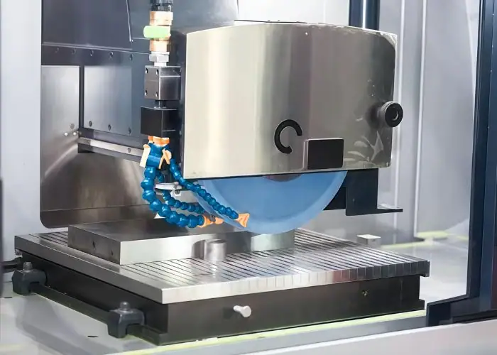
Main Types of Grinding Machines
Grinding machines are classified mainly by the workpiece geometry and grinding operation they perform. A surface grinding machine produces accurate flat surfaces, while a cylindrical grinder works on external round features. Other machines specialize in internal bores, centerless production, tool sharpening, or gear finishing.
| Grinding Machine | Main Function | Typical Components |
| Surface grinding machine | Produces flat and parallel surfaces | Plates, fixture blocks, mold bases |
| Cylindrical grinding machine | Finishes outside diameters | Shafts, pins, rollers |
| Centerless grinding machine | Grinds cylindrical parts without centers | Pins, rods, production shafts |
| Internal grinding machine | Finishes internal diameters | Bearing bores, sleeves |
| Tool and cutter grinder | Shapes or sharpens cutting tools | End mills, drills, reamers |
| CNC grinding machine | Controls complex grinding movements | Precision profiles, production parts |
Machine selection should consider workpiece size and the measurement required. A long shaft may need support against deflection, while a wide plate may require a machine with adequate table travel and stable thermal behavior.
Key Components of a Grinding Machine
A grinding machine contains several systems that must work together to maintain accuracy. The spindle drives the abrasive wheel, while the table or workhead controls the position and movement of the workpiece. Feed mechanisms provide controlled infeed, and the machine structure resists cutting forces.
Important components include:
- Grinding spindle and wheelhead for stable wheel rotation.
- Machine bed, guideways, and feed system for precise motion.
- Worktable, chuck, centers, or fixtures for workpiece support.
- Coolant delivery and filtration system for thermal control.
- Wheel dressing and balancing equipment for consistent cutting.
- CNC controller or manual controls for regulating machine movement.
Grinding Wheels and Abrasive Materials
Grinding wheels contain abrasive grains held together by a bond. Their performance depends on abrasive type, grain size, bond material, wheel grade, and structure. Different combinations provide different cutting behavior, surface finish, and wheel life.
| Abrasive Material | Common Applications | Main Consideration |
| Aluminum oxide | Carbon steel and many alloy steels | General-purpose grinding |
| Ceramic aluminum oxide | Tough steels and demanding applications | Controlled grain fracture |
| Silicon carbide | Cast iron, some nonferrous materials, ceramics | Material compatibility |
| Cubic boron nitride (CBN) | Hardened steel and certain high-temperature alloys | Hard-material grinding |
| Diamond | Carbide, glass, and technical ceramics | Not generally preferred for conventional steel grinding |
A grinding disc is a broader term that may describe abrasive discs used in handheld angle grinders or other equipment. Precision machine grinding wheels should not be confused with general-purpose grinding discs because wheel construction, speed rating, geometry, and dimensional control requirements may differ.
Grinding Wheel Dressing and Truing
Grinding wheel dressing restores cutting effectiveness by exposing fresh abrasive grains and controlling the condition of the wheel surface. Truing corrects the wheel’s geometry, concentricity, or profile so it rotates and contacts the workpiece as intended.
These are related but different maintenance operations. A wheel can have the correct shape but still cut poorly if its grains are dull or loaded with material. Conversely, a sharp wheel with poor geometric form may produce inaccurate surfaces.
Dressing and truing become necessary when grinding force increases, surface finish deteriorates, wheel loading develops, or dimensional consistency changes. Maintaining wheel condition is particularly important for precision production and repeated grinding cycles.
What Are the Main Types of Grinding?
The main types of grinding include surface grinding, cylindrical grinding, centerless grinding, internal grinding, creep-feed grinding, profile grinding, form grinding, tool and cutter grinding, jig grinding, gear grinding, thread grinding, and plunge grinding. Each process is designed for particular part geometries, dimensional requirements, or production conditions.
| Grinding Type | Main Application | Typical Requirement |
| Surface grinding | Flat faces and plates | Flatness and parallelism |
| Cylindrical grinding | External round surfaces | Diameter and roundness |
| Centerless grinding | High-volume round parts | Repeatability and productivity |
| Internal grinding | Holes and bearing bores | Bore accuracy |
| Creep-feed grinding | Deep profiles in difficult materials | Controlled high stock removal |
| Profile and form grinding | Complex shapes | Profile accuracy |
| Tool and cutter grinding | Cutting tools | Edge and tool geometry |
| Jig grinding | Precision holes and locations | Accurate feature positioning |
| Gear and thread grinding | Gears and threads | Tooth or thread geometry |
| Plunge grinding | Localized cylindrical features | Diameter, shoulders, and profiles |
Surface Grinding
Surface grinding produces precise flat surfaces by moving a workpiece relative to a rotating abrasive wheel. It is commonly used for fixture plates, machine components, mold bases, sealing surfaces, and flat precision parts.
A surface grinding machine may use a reciprocating table or rotary table depending on its configuration. The process controls material removal over the target surface to improve flatness, parallelism, thickness consistency, or surface finish.
Surface grinding is particularly valuable after CNC milling when a flat surface requires tighter geometric control. However, thin parts must be supported carefully because magnetic clamping, grinding heat, and residual material stress can affect final flatness.
Cylindrical Grinding
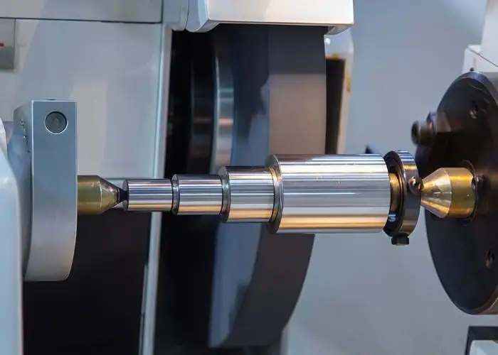
Cylindrical grinding finishes external round surfaces by rotating the workpiece while a grinding wheel removes material from its outer diameter. It is commonly used for shafts, rollers, bearing journals, pins, and precision mechanical components.
The process may use centers, a chuck, or another supporting arrangement. Proper alignment between the workpiece and wheel is necessary to control roundness, taper, and diameter consistency.
Cylindrical grinding is frequently performed after CNC turning. Turning produces most of the shaft geometry, while grinding removes a controlled finishing allowance to achieve the required diameter and surface condition.
Centerless Grinding
Centerless grinding produces precise cylindrical surfaces without holding the workpiece between centers. Instead, the part is supported by a work-rest blade between a grinding wheel and a regulating wheel.
The regulating wheel controls workpiece rotation and, in through-feed operations, axial movement. This makes centerless grinding efficient for producing large quantities of pins, rods, and other round components.
However, centerless grinding requires correct support geometry and setup. Poor wheel alignment, work-rest height, or regulating conditions can create lobing, taper, or inconsistent dimensions. It is most effective when part geometry and production volume suit the process.
Internal Grinding
Internal grinding machines the inside diameter of a hole using a smaller abrasive wheel. It is used for precision bores, bearing races, sleeves, hydraulic components, and other parts requiring accurate internal surfaces.
Internal grinding can be more difficult than external grinding because the wheel diameter is limited by the bore size. Small wheels and long spindles may have lower rigidity, increasing sensitivity to vibration and deflection.
The process must control wheel speed, spindle stiffness, coolant delivery, and bore measurement. Internal grinding is often selected when boring or reaming cannot consistently achieve the required dimensional or surface specifications.
Creep-Feed Grinding
Creep-feed grinding uses a relatively deep cut combined with slow workpiece feed to remove substantial material in a controlled operation. It is often applied to difficult-to-machine alloys, turbine-related components, and complex profiles.
Unlike conventional surface grinding, which generally uses shallow passes, creep-feed grinding can remove more material in a single traverse. It requires appropriate machine power, wheel design, coolant delivery, and process stability.
The method can improve productivity for suitable applications, but thermal damage remains a major concern. High material removal must be supported by effective cooling and controlled wheel condition.
Profile and Form Grinding
Profile grinding produces a defined contour using controlled wheel movement or a suitable wheel shape. Form grinding uses a wheel dressed or manufactured to a specific profile that is transferred to the workpiece.
These methods are used for dies, precision grooves, shaped mechanical components, cutting tools, and specialized surfaces. They are valuable when the final feature requires a repeatable contour rather than a simple flat or cylindrical shape.
The main challenge is maintaining profile accuracy as the wheel wears. Appropriate dressing intervals and dimensional inspection help ensure that the finished contour remains within tolerance.
Tool and Cutter Grinding
Tool and cutter grinding creates, sharpens, or restores cutting tool geometry. It is used for drills, end mills, reamers, and other precision cutting tools that require specific edge angles, relief surfaces, and flute geometry.
A tool grinder may use multiple controlled axes to position the wheel against the cutting tool. CNC tool grinding is particularly useful for complex cutters requiring repeatable edge geometry.
The process affects subsequent machining performance because tool sharpness, symmetry, and edge condition influence cutting force, surface finish, chip formation, and tool life.
Jig Grinding
Jig grinding is a precision process used to finish holes and internal contours where accurate position and geometry are important. It is commonly associated with tooling, dies, mold components, and precision mechanical assemblies.
The machine provides precise positioning while a small grinding wheel finishes the required feature. This is useful when the relationship between multiple holes or profiles must be tightly controlled.
Jig grinding is usually chosen for high-accuracy features rather than general material removal. Its cost and process time should be justified by the part’s functional requirements.
Gear and Thread Grinding
Gear grinding improves gear tooth accuracy, surface finish, and geometric consistency. It is used for precision gears where profile errors, lead errors, and surface defects can affect noise, vibration, and transmission performance.
Thread grinding produces precision external or internal thread forms using a grinding wheel and controlled relative movement. It is particularly useful for hardened components or threads requiring accurate pitch and profile geometry.
Both processes often follow earlier manufacturing operations. The initial geometry is produced by cutting or forming, while grinding provides the required final dimensional and surface control.
Plunge Grinding
Plunge grinding removes material by feeding the grinding wheel directly into the workpiece rather than continuously traversing along its length. It is commonly used to finish specific cylindrical diameters, shoulders, grooves, and short stepped features.
The wheel may have a profile that matches the required shape, allowing multiple related features to be ground during a controlled radial infeed.
Plunge grinding can improve production efficiency for suitable parts, but wheel form, radial force, dressing accuracy, and workpiece support must remain stable to prevent chatter or dimensional variation.
What Are the Different Grinding Techniques?
Grinding techniques differ mainly in coolant use, material removal strategy, operating speed, abrasive selection, and required precision. Common approaches include wet grinding, dry grinding, rough grinding, precision grinding, high-speed grinding, Blanchard grinding, and superabrasive grinding. Each technique is selected to balance material removal, temperature, surface finish, and manufacturing cost.
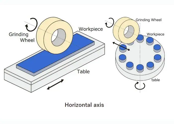
Wet Grinding vs. Dry Grinding
Wet grinding uses coolant or grinding fluid to manage heat, support lubrication where needed, and carry particles away from the cutting zone. It is widely used for precision metal grinding because temperature and wheel condition directly affect dimensional consistency.
Dry grinding operates without liquid coolant. It may be suitable for selected materials or operations where the wheel, machine, dust extraction, and thermal conditions are designed for dry cutting.
The choice depends on material behavior, wheel specification, environmental requirements, and heat sensitivity. Dry grinding should not automatically be considered simpler or cheaper because dust collection and thermal damage control may introduce additional costs.
Rough Grinding vs. Precision Grinding
Rough grinding focuses on removing larger amounts of material, eliminating surface irregularities, or preparing a part for later finishing. It generally prioritizes material removal rate over extremely fine dimensions or surface texture.
Precision grinding focuses on controlled finishing stock and accurate geometry. It typically uses suitable wheel conditioning, smaller finishing increments, stable machine movement, and careful inspection.
A part may require both stages when significant stock must be removed. However, excessive rough grinding immediately before final finishing can introduce heat or distortion that makes precision control more difficult.
High-Speed Grinding
High-speed grinding uses elevated wheel surface speeds with machines and wheels specifically designed for those operating conditions. It can improve productivity in suitable applications by supporting higher material removal rates and different abrasive cutting behavior.
Higher speed does not automatically produce a better surface finish. Wheel strength, spindle capability, grinding forces, coolant delivery, and wheel balance must all be considered.
The maximum permissible wheel speed must never be exceeded. High-speed grinding requires compatible equipment and process validation rather than simply increasing spindle RPM.
Blanchard Grinding
Blanchard grinding is commonly associated with vertical-spindle rotary surface grinding. It is used to remove material efficiently from broad flat surfaces, particularly large plates, machine bases, and industrial components.
A rotating worktable moves the workpiece beneath the grinding wheel. The process can remove material across a substantial area and often leaves a recognizable circular grinding pattern.
Blanchard grinding is useful for stock preparation and large-surface processing, but the achievable finish and geometric accuracy depend on machine condition and setup. A separate precision finishing operation may be required for more demanding specifications.
Superabrasive and Ultra-Precision Grinding
Superabrasive grinding uses materials such as CBN or diamond to process hard and wear-resistant workpieces. CBN is commonly suited to hardened ferrous materials, while diamond is widely used for carbide and advanced ceramics.
Ultra-precision grinding focuses on extremely small dimensional errors and fine surface finishes. It requires highly stable machines, controlled temperature, accurate wheel conditioning, and appropriate metrology.
These approaches are related but not identical. A superabrasive wheel does not automatically create an ultra-precision result, the entire machine, process, workholding, and inspection system must support the required accuracy.
What Are the Key Parameters in Grinding?
The key grinding parameters include wheel speed, workpiece speed, feed rate, depth of cut, grinding pressure, coolant delivery, wheel specification, machine rigidity, and dressing condition. These variables control cutting force, heat generation, material removal rate, wheel wear, dimensional accuracy, and surface finish.
Grinding parameters must be selected as a complete system. Increasing feed or depth can improve productivity but also increase force and thermal load. Changing wheel speed affects abrasive engagement and wear behavior.
The optimum settings depend on wheel diameter, abrasive material, workpiece hardness, grinding method, and part requirements. Precision grinding requires stable parameters rather than simply using the lowest feed or highest available speed.
| Parameter | Main Influence | Risk When Incorrect |
| Wheel speed | Abrasive cutting conditions | Wheel wear, thermal damage, or safety risk |
| Workpiece speed | Contact time and stock removal | Burn, waviness, or poor finish |
| Feed rate | Productivity and grinding load | Excessive force or inefficiency |
| Depth of cut | Material removed per pass | Heat, distortion, wheel wear |
| Coolant | Temperature and debris control | Surface damage or wheel loading |
| Wheel dressing | Sharpness and wheel geometry | Glazing, poor finish, form error |
| Machine rigidity | Resistance to vibration | Chatter and dimensional variation |
What Materials Can Be Ground?
Grinding can be used on many engineering materials, including carbon steel, stainless steel, hardened steel, tool steel, advanced alloys, ceramics, carbide, and selected engineering plastics or composites. Material hardness, thermal behavior, ductility, brittleness, and abrasive compatibility determine the appropriate wheel and grinding parameters.
| Material | Grinding Behavior | Main Concern |
| Carbon steel | Commonly ground with aluminum oxide | Heat and wheel wear |
| Stainless steel | Tough and may work-harden | Burn and wheel loading |
| Hardened steel | Requires suitable abrasive performance | Thermal damage and hardness change |
| Aluminum | Soft, ductile, and prone to wheel loading | Smearing and clogged wheel |
| Carbide | Very hard and wear-resistant | Wheel selection and edge chipping |
| Ceramics | Hard and brittle | Cracks and subsurface damage |
| Plastics | Heat-sensitive and deformable | Melting or distortion |
Steel, Stainless Steel, and Aluminum
Steel is commonly ground for shafts, machine parts, bearing surfaces, and tooling components. Aluminum oxide wheels are widely used for many steel grades, with specific wheel design chosen according to hardness and grinding conditions.
Stainless steel can be more challenging because it may work-harden and generate significant heat. A suitable abrasive, controlled contact conditions, and effective coolant help reduce burn and surface damage.
Aluminum can be ground for selected precision applications, but its ductility may cause abrasive loading and smearing. For many aluminum CNC parts, fine milling or another finishing process may be more economical than conventional grinding.
Hardened Metals and Advanced Alloys
Hardened steels and advanced alloys are important grinding materials because conventional cutting becomes more demanding as hardness and wear resistance increase. Grinding can finish bearing surfaces, hardened shafts, dies, and precision tooling after heat treatment.
CBN abrasives are frequently used for hardened ferrous materials because of their wear resistance and suitability for these applications.
However, hardened materials are also vulnerable to grinding-induced thermal damage. The process must prevent excessive heating, surface softening, residual tensile stress, and cracking that could reduce part performance.
Ceramics and Brittle Materials
Ceramics and other brittle materials can be ground using suitable abrasive wheels, often including diamond-based tools. Grinding is useful for controlling thickness, flatness, and geometry on technical ceramic components.
The main challenge is preventing cracking and subsurface damage. Brittle materials may fracture instead of deforming plastically when abrasive forces are too high.
Wheel specification, depth of cut, machine stability, and coolant control must therefore be selected carefully. For fragile components, grinding may be followed by additional finishing or inspection.
Engineering Plastics and Composites
Some engineering plastics and composites can be ground, but their behavior differs significantly from metals. Plastics may soften or deform under heat, while composites may contain fibers or fillers that respond differently to abrasion.
Grinding can be useful for certain flatness, thickness, or surface preparation requirements. However, conventional grinding is not automatically the best choice for every polymer.
For many CNC plastic parts, sharp cutting tools, controlled feeds, and suitable workholding may provide better results. Grinding should be selected only when the material and surface requirements justify it.
What Are the Advantages and Limitations of Grinding?
Grinding offers high dimensional accuracy, fine surface finishes, good performance on many hardened materials, and precise control of flat, round, or profiled surfaces. Its main limitations include relatively low material removal efficiency in many finishing applications, higher equipment cost, abrasive wheel maintenance, thermal damage risk, and the need for skilled process control.
Grinding is especially valuable when the finished part must meet demanding dimensional or functional requirements. Bearing seats, precision dies, sliding surfaces, and hardened components may benefit from a controlled abrasive finishing process.
However, grinding is not always the most efficient manufacturing method. If CNC milling or turning already meets the drawing specification, an additional grinding operation may increase cost and lead time without improving part performance.
| Aspect | Advantages | Limitations |
| Accuracy | Supports tight dimensions | Sensitive to heat and setup |
| Surface finish | Can produce fine textures | Depends on wheel condition |
| Material capability | Effective for hardened materials | Requires suitable abrasives |
| Geometry | Accurate flat and cylindrical features | Limited for some complex shapes |
| Productivity | Repeatable precision production | May be slow for excessive stock |
| Cost | Can reduce final rework | Additional operation and tooling cost |
Advantages of Grinding
Grinding offers several important benefits for precision manufacturing. It can remove small amounts of material with controlled geometry, making it valuable for final finishing after CNC machining or heat treatment.
Its main advantages include:
- Achieving tight dimensional tolerances on suitable components.
- Improving flatness, roundness, parallelism, and surface finish.
- Finishing hardened steel and other difficult-to-machine materials.
- Producing repeatable surfaces for precision assembly.
- Correcting small dimensional or geometric deviations left by previous operations.
Grinding is especially effective when part performance depends on contact quality. Bearing journals, sealing faces, mating surfaces, and precision tool components often require more than a visually smooth finish.
Limitations of Grinding
Grinding has limitations related to process speed, thermal behavior, wheel wear, and equipment requirements. In many precision applications, grinding is best suited to removing finishing stock rather than producing an entire part from raw material.
Excessive stock removal can create heat and increase grinding time. Wheel dressing, coolant management, machine calibration, and inspection also add manufacturing complexity.
Grinding may be unsuitable when the feature is difficult to access with an abrasive wheel or when a simpler machining process already meets the specification. Selecting grinding unnecessarily can increase cost without adding functional value.
Grinding Cost and Production Efficiency
Grinding cost depends on machine type, workpiece material, wheel specification, required tolerance, surface finish, setup time, and production volume. Tight tolerances and fine finishes generally require more demanding process control and inspection.
For small batches, setup and programming may represent a significant portion of total cost. In production, cycle time, wheel life, dressing frequency, and repeatability become more important.
The total cost should include:
- Workpiece preparation and remaining grinding allowance.
- Machine setup, fixture design, and programming.
- Abrasive wheel consumption and dressing.
- Grinding time and coolant management.
- Inspection, handling, and possible rework.
The goal is to achieve the required function at a practical manufacturing cost, not to specify the finest possible finish on every surface.
Environmental and Safety Considerations
Grinding safety depends on correct wheel selection, guarding, secure workholding, proper mounting, dust or coolant management, and trained machine operation. Abrasive wheels rotate at high speeds and can present serious hazards if damaged or used outside their approved limits.
Operators must follow applicable safety procedures for wheel inspection, speed ratings, machine guards, personal protective equipment, and safe maintenance. Abrasive wheels should never be operated above their rated maximum speed.
Environmental control also matters. Grinding may generate metal particles, abrasive dust, coolant mist, and used fluids. Appropriate filtration, collection, and disposal practices help protect workers and maintain a stable manufacturing environment.
What Are Common Grinding Problems and How Can They Be Prevented?
Common grinding problems include grinding burns, excessive heat, chatter, poor surface finish, wheel glazing, abrasive loading, dimensional variation, taper, and workpiece deformation. These defects usually result from unsuitable wheel specification, incorrect cutting parameters, poor cooling, unstable workholding, wheel wear, or machine condition.
Troubleshooting should begin by identifying the actual cause of the defect. For example, a rough surface may result from vibration, inappropriate wheel dressing, or workpiece loading rather than simply excessive feed.
A process correction should address the entire grinding system. Changing one parameter without checking wheel condition, coolant, machine stability, and material behavior may produce temporary improvement without eliminating the root cause.
| Problem | Likely Cause | Practical Prevention |
| Grinding burn | Excess heat or wheel rubbing | Improve cooling and wheel sharpness |
| Chatter marks | Vibration or unstable setup | Improve rigidity and wheel balance |
| Poor surface finish | Incorrect wheel or dressing | Optimize wheel condition and feed |
| Wheel loading | Material accumulation in wheel pores | Select suitable wheel and dressing |
| Dimensional drift | Thermal growth or wheel wear | Control temperature and inspection |
| Workpiece deformation | Clamping stress or heat | Improve support and stock removal |
Grinding Burns and Excessive Heat
Grinding burn occurs when excessive heat alters the surface condition of a workpiece. Hardened steels are especially vulnerable because thermal exposure can change surface hardness, residual stress, or microstructure.
Burn may appear as discoloration in some materials, but visible color is not a reliable indication of all grinding damage. A surface can experience metallurgical changes without obvious marks.
Prevention requires suitable wheel sharpness, appropriate cutting parameters, effective coolant delivery, and controlled grinding forces. Critical hardened components may require additional verification when grinding burn is a significant functional risk.
Chatter and Poor Surface Finish
Chatter produces repetitive marks or waviness caused by unstable vibration between the wheel and workpiece. It may result from wheel imbalance, weak fixturing, spindle problems, unsuitable wheel specification, or unstable cutting conditions.
Poor surface finish can also develop without obvious chatter. Wheel glazing, inappropriate abrasive grain size, dressing condition, or debris accumulation may produce roughness and scratches.
The solution should match the cause. Improving wheel balance, restoring sharpness, checking the fixture, and adjusting the grinding parameters can improve stability. Surface finish should then be measured to confirm the correction.
Grinding Wheel Wear and Loading
Wheel wear occurs as abrasive grains fracture, dull, or detach during grinding. Some wheel wear is necessary because fresh cutting edges must become available for stable cutting.
Wheel loading occurs when workpiece material accumulates between abrasive grains. This reduces cutting effectiveness and increases rubbing, heat generation, and surface damage risk.
Appropriate abrasive selection and wheel dressing help control these problems. The correct dressing frequency depends on material, wheel specification, surface finish requirement, and production conditions.
Dimensional Errors and Workpiece Deformation
Grinding dimensional errors may result from thermal expansion, wheel wear, spindle movement, fixture distortion, or incorrect machine offsets. Thin components and long shafts are especially sensitive because they can bend or move during grinding.
For example, excessive clamping force may temporarily flatten a thin plate. After grinding and unclamping, the plate may return toward its original shape and fail flatness inspection.
Prevention requires suitable support, stable temperature, controlled finishing passes, and measurement after the part has reached the appropriate inspection condition.
Where Is Grinding Used in CNC Manufacturing?
Grinding is used in CNC manufacturing to finish precision components requiring accurate dimensions, controlled surface texture, flatness, roundness, or hardened material processing. Major application areas include automotive, industrial equipment, medical devices, aerospace, tooling and molds, electronics, and semiconductor manufacturing.
Grinding is often part of a larger manufacturing sequence. CNC milling or turning creates the primary geometry, heat treatment may provide the required hardness, and grinding finishes selected critical surfaces.
The process is especially valuable where surface condition influences mechanical function. Precision sliding faces, sealing surfaces, bearing seats, and mating components may require controlled geometry and finish to operate reliably.
| Application | Typical Parts | Why Grinding Is Used |
| Automotive | Shafts, gears, bearing components | Roundness and surface control |
| Industrial equipment | Guide surfaces, precision sleeves | Dimensional consistency |
| Medical | Surgical tools, precision inserts | Accuracy and surface quality |
| Aerospace | Hardened shafts, precision mechanisms | Controlled tolerances |
| Tooling and molds | Mold plates, inserts, dies | Flatness and tool geometry |
| Electronics | Precision fixtures and ceramic parts | Flatness and surface preparation |
Automotive Components
Automotive grinding is commonly used for shafts, bearing surfaces, gears, camshafts, crankshafts, and other components requiring accurate round or shaped surfaces.
For rotating components, diameter, roundness, and surface finish influence friction, wear, noise, and assembly fit. Grinding is valuable because it can improve these characteristics after turning, heat treatment, or other manufacturing operations.
In production, repeatability is particularly important. Wheel wear, dressing intervals, in-process measurement, and stable workholding help maintain consistent results across large batches.
Industrial Equipment and Precision Machinery
Industrial machinery uses grinding for guideways, machine components, bearing journals, hydraulic sleeves, precision plates, and accurately finished mating surfaces.
These components often depend on flatness, parallelism, or roundness for proper assembly and operation. Poor geometry can cause uneven contact, alignment problems, increased wear, or reduced service life.
Surface grinding is common for flat mechanical components, while cylindrical and internal grinding are used for rotating and bore-related features. The choice depends on functional geometry rather than the industry alone.
Medical Devices and Instruments
Medical devices and instruments may require precision grinding for hardened stainless steel components, small mechanical features, surgical instruments, and selected implant-related parts.
Surface integrity is particularly important. Dimensional accuracy alone may not be enough if grinding leaves burns, burrs, contamination, or unsuitable surface texture.
The process must be matched to the material and intended function. Appropriate inspection and cleaning help confirm that the finished surface meets the necessary engineering requirements.
Aerospace Components
Aerospace applications may use grinding for precision shafts, landing-gear-related components, hardened mechanical interfaces, and other high-performance parts requiring controlled geometry.
These components can involve demanding alloys, strict inspection requirements, and high-value materials. Grinding conditions must therefore be selected carefully to protect surface integrity and avoid thermal damage.
The process may be used after turning, milling, or heat treatment. In these cases, controlled grinding allowance and documented inspection are important for dimensional consistency.
Tooling, Molds, and Dies
Grinding is widely used for mold bases, die plates, precision inserts, punches, cutting tools, and hardened tooling components.
Tooling surfaces often require flatness, parallelism, accurate profiles, and controlled dimensions because small errors can transfer directly into manufactured products.
Surface grinding can finish mold plates and reference faces. Form or profile grinding may be used for shaped inserts, while tool grinding maintains cutting-edge geometry. These operations support tool accuracy, assembly, and service life.
Electronics and Semiconductor Components
Electronics and semiconductor manufacturing may use specialized grinding processes for ceramic components, precision fixtures, wafer-related processing, and other parts requiring fine geometry or controlled thickness.
These applications can involve hard or brittle materials that require carefully selected abrasives and low-damage cutting conditions. Flatness, thickness uniformity, cleanliness, and subsurface integrity may be more important than general appearance.
The grinding method must match the material and application. Conventional metal grinding settings should not be applied directly to semiconductor or advanced ceramic components without validation.
How to Choose the Right Grinding Process?
The right grinding process should be chosen according to part geometry, material hardness, tolerance, surface finish, remaining machining allowance, production quantity, and total manufacturing cost. The selected process must achieve the functional requirements without unnecessary grinding operations, excessive thermal risk, or avoidable production expense.
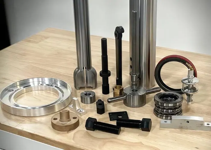
Grinding process selection begins with the engineering drawing. Critical surfaces should be identified first, followed by the required dimensions, geometric tolerances, material condition, and surface texture.
The manufacturing route must then be reviewed. A part may require turning followed by cylindrical grinding, milling followed by surface grinding, or heat treatment followed by precision finishing. The correct sequence depends on material stability and final part function.
| Selection Factor | Engineering Question | Likely Direction |
| Flatness | Does the part need a precise flat face? | Surface grinding |
| Outside diameter | Is accurate roundness required? | Cylindrical grinding |
| Production quantity | Are many similar shafts required? | Centerless grinding |
| Bore accuracy | Does an internal diameter need finishing? | Internal grinding |
| Complex profile | Is a shaped surface required? | Form or profile grinding |
| Material hardness | Has the part been hardened? | Suitable precision abrasive process |
| Cost | Can milling or turning meet the requirement? | Avoid unnecessary grinding |
Match the Process to Part Geometry
Part geometry is the first consideration because different grinding processes are designed for different surfaces.
Flat plates and precision reference faces are generally suited to surface grinding. Round shafts may require cylindrical or centerless grinding. Internal bores require suitable internal grinding equipment.
More complex shapes may need form grinding, profile grinding, or another specialized process. A process should not be chosen only because a supplier has a particular grinder available.
Consider Material Hardness and Machinability
Material hardness and machinability influence abrasive selection, wheel wear, heat generation, and the feasibility of grinding.
Hardened steel may require a different wheel and cutting strategy from aluminum or stainless steel. Brittle ceramics require particular attention to cracking, while ductile materials may load the wheel.
The material’s condition also matters. A heat-treated part may behave differently from the same alloy before hardening. Material selection should therefore be coordinated with grinding and inspection requirements.
Evaluate Tolerance and Surface Finish Requirements
Tolerance and surface finish determine whether grinding is necessary and how demanding the process must be.
A part with standard dimensions and a moderate surface finish may be completed through CNC milling or turning. A precision bearing seat or flat reference surface may require an additional grinding operation.
For tight requirements, the drawing should clearly distinguish dimensional tolerance, geometric tolerance, and surface roughness. A specified Ra value does not automatically guarantee flatness, roundness, or accurate feature location.
Balance Grinding Cost and Production Volume
Grinding cost depends on setup, programming, machine capability, abrasives, dressing, inspection, and cycle time.
For prototypes and small batches, setup may dominate the cost. For larger production quantities, stable workholding, wheel life, automated measurement, and repeatability become increasingly important.
A lower machine rate does not always produce the lowest total cost. A more suitable grinder may reduce processing time, rework, and inspection variation.
The best decision considers total manufacturing cost together with the risk of failing the required part specification.
Decide When Grinding Is Needed After CNC Machining
Grinding should be added after CNC machining when the required geometry, accuracy, surface finish, or material condition cannot be achieved reliably through milling or turning alone.
Typical situations include:
- A hardened steel shaft requiring a precision bearing diameter.
- A milled plate requiring tighter flatness or parallelism.
- A precision bore requiring final geometric correction.
- A mold insert requiring accurate mating surfaces.
- A component requiring fine finishing after heat treatment.
Grinding is not automatically required for every precision part. Engineers should compare the final requirements with the achievable capability of the initial machining process before adding a secondary operation.
FAQs
What Tolerances Can Precision Grinding Achieve?
Precision grinding can achieve dimensional tolerances around ±0.005–0.01 mm on suitable parts and controlled equipment, while specialized processes may reach micron-level accuracy. Actual capability depends on part size, geometry, material, machine condition, temperature, and inspection methods. Dimensional tolerance must also be distinguished from flatness, roundness, and surface roughness. For example, a ground part may meet a ±0.005 mm size tolerance but still require separate verification of its geometric tolerances. These values are examples, not universal guarantees.
How Does Grinding Compare With CNC Milling for Final Finishing?
Grinding generally removes smaller amounts of material using abrasive grains, while CNC milling uses defined cutting edges to produce geometry and finished surfaces. Grinding can be advantageous for hardened materials, fine surface finishes, and demanding flatness or roundness requirements. CNC milling is usually more efficient for complex pockets, contours, and larger stock removal. If milling already achieves the specified tolerance and surface finish, grinding may add unnecessary cost. The correct choice depends on feature geometry and functional requirements.
Can Grinding Be Used on Hardened Steel and Stainless Steel?
Yes. Grinding is commonly used on hardened steel and stainless steel, but wheel selection and thermal control are critical. Hardened steel may be ground with suitable aluminum oxide or CBN wheels, while stainless steel requires attention to wheel loading, rubbing, and heat generation. Grinding can finish precision shafts, bearing surfaces, and tooling after hardening. However, improper grinding conditions may cause surface burns, hardness changes, or residual stress. The material grade and heat-treatment condition should guide process selection.
What Causes Grinding Burns and How Can They Be Prevented?
Grinding burns result from excessive heat at the wheel-workpiece contact zone. Common causes include dull abrasive grains, excessive grinding forces, unsuitable parameters, poor coolant delivery, and wheel glazing. On hardened steel, thermal damage may reduce surface hardness or create harmful residual stresses. Prevention involves selecting a suitable wheel, maintaining sharp cutting grains, optimizing grinding conditions, and directing coolant effectively. Visual inspection alone may not detect every type of burn, so critical parts may require additional surface-integrity testing.
When Should a CNC-Machined Part Be Finished by Grinding?
A CNC-machined part should be finished by grinding when milling or turning cannot consistently meet the required tolerance, flatness, roundness, surface finish, or hardened-material condition. For example, a turned bearing journal may need cylindrical grinding to improve diameter and roundness, while a milled tooling plate may require surface grinding for tighter flatness. Grinding must be planned before the final machining stage so sufficient finishing allowance remains. Adding grinding unnecessarily increases cost, handling, and lead time without necessarily improving performance.
Conclusion
Grinding is an important precision manufacturing process for producing accurate dimensions, controlled surface finishes, and reliable functional surfaces. Its effectiveness depends on selecting the correct grinding method, abrasive wheel, machine, cutting parameters, coolant system, and inspection approach. Surface grinding, cylindrical grinding, internal grinding, and other methods each serve different applications. The best manufacturing strategy uses grinding when the part’s geometry, material, tolerance, or surface condition requires precision beyond conventional cutting operations.
At TiRapid, we provide precision CNC machining and manufacturing services for custom metal and plastic components. Our team supports CNC milling, turning, DFM analysis, material selection, surface finishing, and quality inspection to help customers produce accurate, stable, and manufacturable parts for real engineering applications.