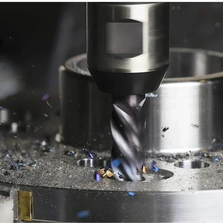
Taper turning is a CNC and lathe machining process used to create conical, angled, or gradually changing diameters on round parts. It is widely used for shafts, pins, tool holders, nozzles, bushings, valve parts, and mechanical components that require accurate alignment, sealing, locking, or assembly fit. A well-machined taper helps parts locate smoothly, transfer load properly, and maintain repeatable contact during use.
This guide explains what taper turning is, how taper geometry works, which machining methods are commonly used, how CNC taper turning controls angle and surface quality, what materials affect machining stability, where tapered features are applied, and what design factors help manufacturers produce accurate tapered shafts, bores, and precision turned components.
What Is Taper Turning?
Taper turning is the process of machining a surface where the diameter changes gradually along the length of a rotating workpiece. Unlike straight turning, which produces a constant diameter, taper turning creates an angled profile that may be external, internal, short, long, shallow, or steep depending on the function of the part.
How Taper Geometry Works?
A taper is defined by the difference between two diameters over a specific length. The angle may be shown directly on the drawing, or it may be defined by taper ratio, taper per length, large diameter, small diameter, and overall taper length. For machining, these values must be converted into a controlled tool path that follows the required conical profile.
The most important geometry factors are taper angle, length, start diameter, end diameter, and datum reference. If any of these values are unclear, the machined taper may fit poorly even when the surface looks correct. A small angle error can create contact only at one end of the taper instead of across the intended bearing surface.
In precision CNC turning, taper geometry should be linked to the mating component. A taper used for location may need different tolerance control than a taper used for sealing, clamping, or tool holding. Understanding the function helps the machinist choose the right finishing method, measurement approach, and inspection standard.
External and Internal Tapers
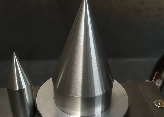
External tapers are machined on the outside diameter of a round part. They are common on tapered shafts, cones, pins, nozzles, machine tool interfaces, and alignment features. The cutting tool removes material along the rotating surface until the diameter changes smoothly from one end to the other.
Internal tapers are machined inside holes or bores. They may be used for seats, sockets, tapered sleeves, valve features, or matching assembly interfaces. Internal taper turning is more difficult because tool access, boring bar rigidity, chip evacuation, and measurement access are more limited than external turning.
Both external and internal tapers require stable setup and accurate tool movement. Internal tapers often need special boring tools, smaller cutting depths, and closer attention to vibration. External tapers are usually easier to inspect, but long and slender parts can still deflect if support and cutting forces are not controlled.
Why Taper Fits Matter in Mechanical Assemblies?
Tapered features are often used when parts need self-centering, controlled contact, or easier assembly. A taper can guide one part into another, distribute force over a larger contact area, or create a tight mechanical fit without relying only on a flat shoulder or straight diameter.
The quality of the taper affects how the part behaves in service. A poor taper angle can cause uneven contact, wobble, leakage, excessive stress, or difficulty during assembly. Even when the major and minor diameters are close to specification, incorrect taper form may still create functional problems.
For engineering parts, taper turning should not be treated as a simple visual shape. The taper angle, surface finish, roundness, concentricity, and datum relationship all affect final performance. This is why tapered components often need both dimensional inspection and fit-based evaluation with the mating part or gauge.
How Taper Turning Works in CNC Machining?
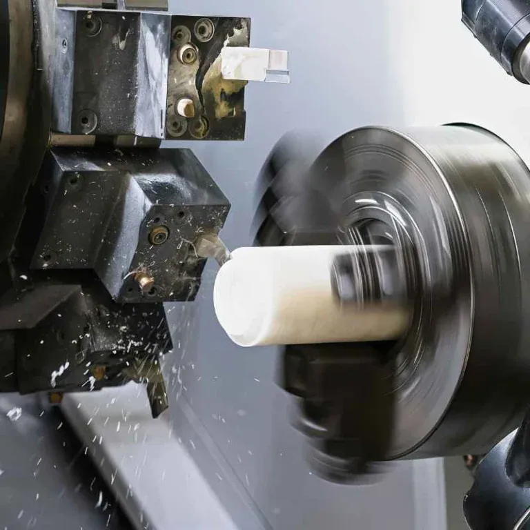
In CNC taper turning, the workpiece rotates in the spindle while the cutting tool follows a programmed angled path. The machine controls X-axis and Z-axis movement at the same time, allowing the tool to remove material along a straight conical line or a more complex tapered profile.
Workpiece Rotation and Tool Path Control
Turning depends on the rotation of the workpiece and the linear movement of a cutting tool. For taper turning, the tool does not simply move parallel to the centerline. Instead, it moves with a coordinated X and Z path so the diameter changes gradually along the taper length.
In CNC turning, this movement is programmed from the drawing or CAD model. The machinist defines the start point, end point, taper angle, clearance, roughing allowance, and finishing path. This allows the machine to repeat the same taper more consistently than many manual methods.
Tool path control is especially important when the taper connects to shoulders, grooves, threads, radii, or sealing faces. If the tool enters or exits poorly, it may leave witness marks, undercuts, or blend errors. Good programming keeps the taper clean while protecting adjacent functional features.
Taper Angle Calculation
The taper angle can be calculated from the difference between the large and small diameters over the taper length. In CNC machining, this calculation helps define the tool path and ensures that the programmed movement matches the drawing requirement rather than relying on visual adjustment.
A shallow taper may look simple, but it can be sensitive to small dimensional changes. If the taper length is long, a small offset error can produce a measurable angle deviation. If the taper is short and steep, tool nose radius compensation and approach strategy become more important.
When the drawing includes taper ratio, included angle, or half-angle, the manufacturer must interpret it correctly. Confusing included angle with side angle can double the error. For precision taper turning, angle definition should be reviewed before machining so inspection and production use the same reference.
Roughing and Finishing Strategy
Most taper turning operations use roughing and finishing stages. Roughing removes most of the material quickly while leaving a controlled allowance. Finishing then produces the final taper angle, diameter, surface finish, and form accuracy with lighter cutting forces.
Roughing should avoid excessive tool pressure, especially on long shafts or thin-wall components. Heavy cuts may create deflection, heat, and vibration that affect the final taper. A stable roughing path leaves enough material for finishing but does not distort the part before the final pass.
Finishing should use suitable cutting speed, feed rate, tool nose radius, and tool compensation. The final pass must produce a smooth surface without chatter or taper mismatch. For high-precision parts, the machinist may measure the taper after a trial pass and adjust offsets before the final cut.
Common Taper Turning Methods
Taper turning can be performed by several methods depending on part size, taper angle, production volume, equipment, and accuracy requirement. Manual lathes and CNC lathes use different approaches, but the goal is the same: create a controlled conical surface with stable geometry and surface finish.
| Method | How It Works | Best Used For | Main Limitation |
| CNC taper turning | Programmed X-Z tool movement creates the taper | Precision parts, repeat production, complex turned components | Requires correct programming and setup |
| Compound rest method | Tool is fed at an angle using the compound slide | Short tapers on manual lathes | Limited length and operator-dependent accuracy |
| Tailstock set-over | Workpiece axis is offset between centers | Long external tapers | Not suitable for internal tapers |
| Taper attachment | Attachment guides the tool at a set angle | Longer manual lathe tapers | Requires setup time and proper alignment |
| Form tool method | A tool with taper shape cuts the profile directly | Very short tapers or chamfer-like features | High cutting force and limited taper length |
CNC Taper Turning
CNC taper turning is the preferred method for many precision turned parts because the taper can be programmed, repeated, adjusted, and inspected with high consistency. The machine controls the tool path directly, so it can produce external tapers, internal tapers, stepped transitions, grooves, and blended profiles in one setup.
The advantage of CNC taper turning is not only speed. It also improves repeatability when multiple parts require the same angle and diameter relationship. Once the program and setup are verified, the machine can reproduce the taper while the operator manages tool wear, offsets, and inspection results.
CNC taper turning is especially useful when the taper must align with other machined features. If a part has threads, shoulders, bores, grooves, or milled flats, machining the taper in the same setup can reduce concentricity errors and improve the relationship between all functional surfaces.
Compound Rest Method
The compound rest method is a traditional manual lathe method where the compound slide is set to the required taper angle. The cutting tool is then fed along that angled slide to machine a short taper on the rotating workpiece. It is simple and useful for prototypes or low-volume work.
This method works best for short tapers because the compound slide travel is limited. Accuracy depends on how well the angle is set, how smoothly the operator feeds the tool, and how stable the workpiece is during cutting. It can produce good results, but repeatability is more operator-dependent than CNC turning.
For industrial production, the compound rest method is less efficient when many identical tapers are needed. It may still be valuable for repair work, one-off parts, or simple manual operations, but complex parts with tight tolerances usually benefit from CNC programming and controlled tool compensation.
Tailstock Set-Over Method
The tailstock set-over method is used on a lathe when machining long external tapers between centers. The tailstock is offset slightly from the spindle centerline, causing the workpiece axis to sit at an angle. A straight tool feed then creates a tapered surface along the part length.
This method can be practical for long shafts because it does not depend on the limited travel of a compound slide. It is often associated with traditional lathe work where a gradual external taper is required over a longer distance. However, setup and alignment are very important.
The main limitation is that tailstock set-over is not suitable for internal tapers and may affect center alignment. It is also less flexible than CNC taper turning. For parts that require tight coaxiality, multiple features, or repeat production, CNC turning usually offers better control and easier correction.
Taper Attachment and Form Tool Methods
A taper attachment guides the cutting tool along a fixed angle while the lathe carriage moves. This allows longer tapers to be machined without offsetting the tailstock. It can be useful on manual lathes when the taper length is too long for the compound rest method.
The form tool method uses a cutting tool ground to the taper shape. Instead of feeding along the taper length, the tool shape creates the taper directly. This method is generally limited to short tapers because a wide tool contact area increases cutting force, heat, and chatter risk.
Both methods have practical value, but they require careful setup. Taper attachments depend on alignment and angle setting, while form tools depend on tool geometry and rigidity. For precision CNC parts, these methods are less common than programmed taper turning, but they remain useful in selected manufacturing situations.
Taper Turning Materials and Machining Behavior
Material selection has a strong effect on taper turning stability, surface finish, tool wear, and tolerance control. The same taper design may be easy to machine in aluminum but more difficult in stainless steel, titanium, or engineering plastics because each material reacts differently to heat, cutting force, and tool geometry.
Aluminum Taper Turning
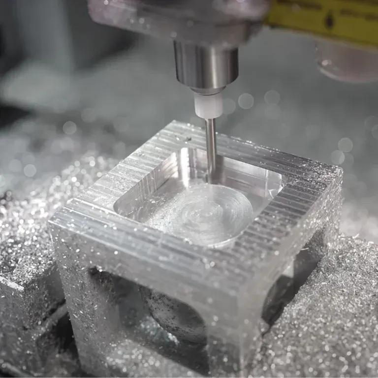
Aluminum taper turning is often efficient because aluminum cuts easily, removes material quickly, and can produce good surface finish with the right tool geometry. It is commonly used for lightweight shafts, sleeves, housings, adapters, nozzles, and prototype components that require accurate angled surfaces.
The main machining concerns are built-up edge, burr formation, and surface marks. Soft aluminum alloys may stick to the cutting edge if the tool is not sharp or the cutting parameters are poorly selected. This can affect taper surface quality and create inconsistent dimensions during finishing.
For precision aluminum tapers, sharp inserts, proper coolant, stable clamping, and controlled finishing passes are important. If the taper is used for sealing or alignment, surface finish and edge break should be reviewed carefully so the part fits smoothly without galling or assembly interference.
Stainless Steel Taper Turning
Stainless steel taper turning is more demanding because the material can work-harden, generate heat, and increase tool wear. It is used for corrosion-resistant shafts, fittings, valve parts, medical tooling components, industrial equipment parts, and assemblies that require strength and clean surfaces.
The key risk is unstable cutting. If feed rate, tool pressure, or tool sharpness is not controlled, stainless steel may harden at the surface and become more difficult to cut on the next pass. This can lead to poor finish, dimensional drift, chatter, or reduced tool life.
Successful stainless steel taper turning requires rigid setup, suitable insert grade, proper coolant, and consistent cutting engagement. For tight taper tolerances, finishing passes should avoid rubbing and should remove enough material to create a clean cut without overheating the surface.
Titanium Taper Turning
Titanium is used when strength-to-weight ratio, corrosion resistance, and high-performance applications matter. Taper turning titanium requires careful control because the material has low thermal conductivity, meaning heat tends to stay near the cutting zone and accelerate tool wear.
The machining strategy should reduce heat concentration and avoid tool rubbing. Sharp tools, rigid setups, controlled cutting speeds, and effective coolant are important. If the tool wears during finishing, the taper angle and surface quality can change before the operator notices the problem.
For titanium tapered parts, conservative cutting parameters and frequent inspection are often necessary. Thin sections or long shafts may also deflect under cutting force. The machining plan should balance accuracy, tool life, and surface integrity rather than simply maximizing material removal rate.
Engineering Plastic Taper Turning
Engineering plastics such as PEEK, PTFE, PVDF, and Delrin can also be taper turned for precision components, bushings, seats, fluid parts, and custom mechanical features. These materials are very different from metals because they can deflect, expand, or deform under heat and clamping pressure.
PTFE and some softer plastics may move during machining, making taper accuracy harder to hold. PEEK and Delrin are generally more stable but still require sharp tools and controlled cutting forces. Excessive heat can change dimensions, smear the surface, or leave burr-like edges.
For plastic taper turning, the setup should avoid over-clamping and should allow the material to remain stable before final inspection. Finishing cuts may need lighter pressure and sharp tool edges. When the taper must mate with another part, functional fit should be considered along with measured dimensions.
Taper Turning Tolerances and Quality Control
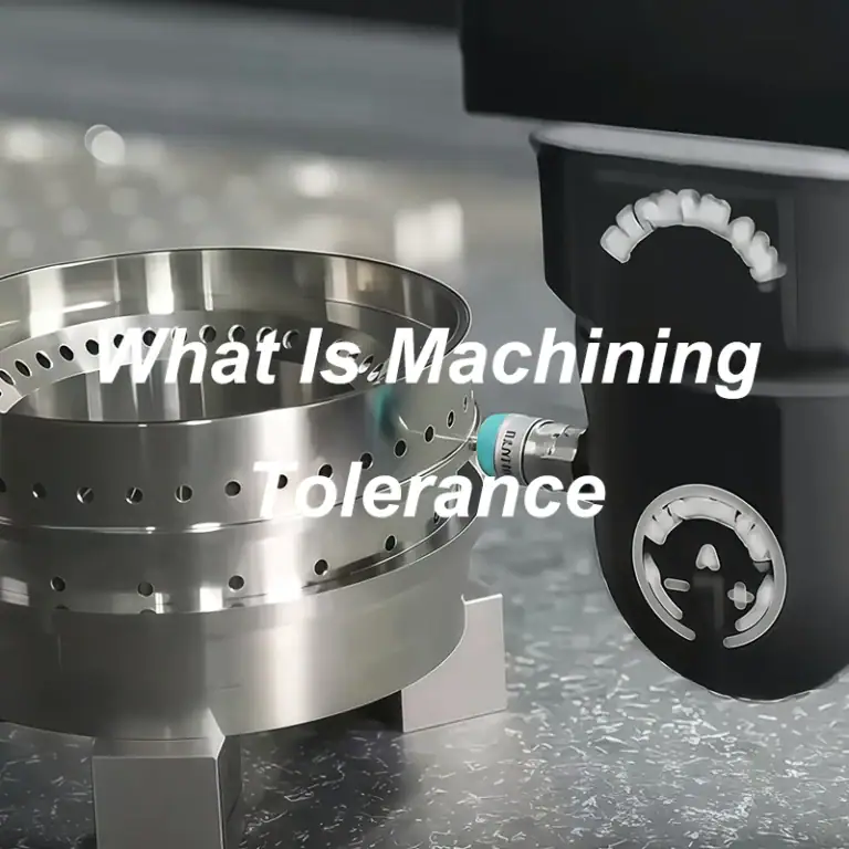
Taper turning tolerance is not only about the large and small diameters. A precision taper also depends on angle accuracy, straightness of the tapered surface, roundness, concentricity, surface finish, and the relationship between the taper and other datums on the part.
Angle Accuracy and Diameter Control
A taper can meet one diameter and still fail if the angle is wrong. This is why both end diameters and taper length should be controlled together. The drawing should define whether the most important requirement is angle, taper ratio, fit, contact pattern, or exact end diameters.
In CNC machining, diameter control depends on tool offset, tool wear, thermal stability, and measurement feedback. During production, the machinist may adjust offsets after inspecting the first part. For long runs, tool wear compensation helps keep the taper within specification.
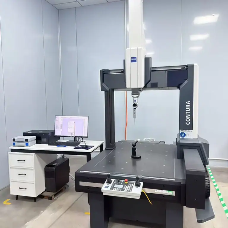
Angle accuracy becomes more sensitive when the taper is long or when the mating part requires full contact. Small changes in X-axis position can shift the taper form. For critical components, inspection may include gauge fitting, sine measurement, CMM checks, or optical comparison.
Surface Finish and Contact Quality
Surface finish affects how a taper seats, seals, slides, or grips. A rough taper may create high contact points, friction, leakage, or wear. A very smooth taper may be required for sealing surfaces, while a functional mechanical taper may need a controlled finish that supports stable contact.
Tool nose radius, feed rate, cutting speed, and material behavior all influence taper finish. Chatter marks are especially harmful because they create uneven contact around the circumference. Burrs at taper ends can also prevent proper seating even if the taper angle is correct.
The required finish should match the application. A cosmetic taper on a cover part does not need the same surface control as a valve seat or tool-holder taper. Defining the functional surfaces helps the manufacturer focus finishing and inspection on the areas that affect performance.
Concentricity and Datum Control
Tapered features often need to be concentric with another diameter, bore, thread, or shoulder. If the taper is accurate by itself but not aligned to the part datum, assembly problems can still occur. This is common in shafts, adapters, spindle-related parts, and precision locating components.
The best way to control concentricity is to machine related turned features in one setup whenever possible. Re-clamping can introduce runout, especially on slender parts or parts with limited gripping surfaces. Stable workholding and datum planning are essential for accurate taper relationships.
Inspection should confirm both taper geometry and datum alignment. Runout checks, CMM measurement, bore gauges, taper gauges, and functional mating tests may be used depending on the part. For high-precision taper turning, quality control should reflect how the part will actually be assembled.
Design Considerations for Tapered CNC Parts
Good taper design makes machining easier, inspection clearer, and assembly more reliable. Engineers should define the taper function early because a self-locating taper, sealing taper, cosmetic taper, and tool-interface taper may need different tolerances, surface finish, and datum requirements.
Define the Taper Function Clearly
The taper should be designed around its purpose. If it is used for alignment, the angle and concentricity may matter most. If it is used for sealing, surface finish and contact quality become more important. If it is used for assembly clearance, the tolerance may be less demanding.
A drawing that only shows a tapered shape without functional notes can create confusion. The manufacturer may not know whether the taper is critical or only a clearance feature. Adding datum references, tolerance callouts, surface finish requirements, and mating information can prevent unnecessary risk.
When a taper must match another component, the mating part should be considered during design review. Even a precisely machined taper can fail if the mating geometry is defined differently. Shared angle references and clear inspection methods help both parts fit as intended.
Avoid Overly Thin or Flexible Tapered Sections
Long, thin, or hollow tapered parts can deflect during turning. Cutting pressure, chucking force, tailstock support, and internal stress can change the actual geometry. The result may be taper error, chatter, ovality, or poor repeatability between parts.
Designers should consider wall thickness, unsupported length, material stiffness, and clamping location. If the part is too flexible, it may need support from a center, steady rest, soft jaws, custom fixture, or a modified machining sequence. These decisions should be made before production.
For thin-wall tapered sleeves or plastic components, inspection should also consider relaxation after machining. Some parts may change slightly after being unclamped. A stable design reduces manufacturing difficulty and helps the finished taper remain within tolerance after the part leaves the machine.
Control Transitions, Shoulders, and Edge Breaks
Tapers rarely exist alone. They often connect to straight diameters, shoulders, grooves, radii, threads, holes, or sealing faces. The transition area can be difficult to machine because the tool must enter and exit without leaving marks, undercuts, or burrs.
A sharp transition may be required for function, but it can increase tool stress and inspection difficulty. A small radius or relief groove may improve machinability if the design allows it. The correct choice depends on how the taper contacts the mating part and whether adjacent features need clearance.
Edge break is also important. A burr at the end of a taper can prevent full seating, while an excessive chamfer can reduce contact area. Drawings should define critical edges clearly, especially when the taper is used for sealing, alignment, or repeatable mechanical location.
Taper Turning Applications
Taper turning is used across many industries because tapered geometry solves common assembly, alignment, sealing, and load-transfer problems. The process is especially valuable when round parts need controlled diameter change rather than a simple straight shaft or step-turned profile.
Automotive and Industrial Equipment
Automotive components may use tapered features for shafts, pins, fittings, adapters, fluid connectors, and rotating assemblies. A controlled taper can help parts align during assembly, reduce looseness, or create a reliable seat between mating components.
Industrial equipment often uses taper turning for bushings, sleeves, valve parts, tooling holders, rollers, and mechanical transmission components. These parts may require strength, wear resistance, corrosion resistance, and repeatable fit in working environments.
For these applications, the taper must be practical to machine and durable in use. Material selection, surface finish, and tolerance should be matched to load, speed, contact pressure, and maintenance requirements. A small geometry issue can create vibration or premature wear in mechanical systems.
Medical, Aerospace, and Automation Parts
Medical tooling and device-related components may use tapered features where smooth assembly, precise location, or controlled fluid passage is required. In these parts, surface finish, burr control, and material compatibility can be as important as dimensional tolerance.
Aerospace parts may require titanium, stainless steel, or aluminum tapers for lightweight structures, fittings, shafts, and precision interfaces. These components often need strong process control because taper geometry may affect alignment, sealing, or fatigue performance.
Automation systems use tapered pins, locating features, grippers, tool interfaces, and custom turned components. In these applications, repeatability matters. If the taper is inconsistent, automated assembly or motion systems may experience misalignment, jamming, or unstable positioning.
Electronics, Robotics, and Precision Tooling
Electronics and robotics parts may include small tapered pins, precision sleeves, connector components, sensor housings, and compact mechanical interfaces. These features often require clean edges and stable dimensions because parts are small and assembly space is limited.
Precision tooling uses taper turning for fixtures, alignment pins, holders, punches, inserts, and locating components. A taper can help tools seat repeatably, transfer force, or maintain position during machining, inspection, or assembly operations.
For small precision parts, machining feasibility depends on tool access, part rigidity, and inspection method. Micro-sized tapers may require special tools and careful process planning. The smaller the feature, the more important it becomes to control burrs, runout, and surface finish.
Taper Turning vs Step Turning
Taper turning and step turning are both common turning operations, but they solve different design problems. A stepped part changes diameter suddenly at a shoulder, while a tapered part changes diameter gradually along a controlled length. Choosing the wrong feature can affect assembly, stress, and machining cost.
| Item | Taper Turning | Step Turning |
| Geometry | Gradual diameter change | Sudden diameter change |
| Main Function | Alignment, seating, sealing, controlled fit | Shoulder location, diameter change, stop face |
| Tool Path | Angled X-Z movement | Straight turning and shoulder cutting |
| Inspection Focus | Angle, contact, end diameters, surface finish | Diameters, shoulder position, perpendicularity |
| Common Risk | Angle error or poor contact | Burrs, shoulder mismatch, stress concentration |
When to Use Taper Turning?
Taper turning should be used when a part needs gradual engagement, self-centering, contact over an angled surface, or controlled assembly fit. It is useful when the geometry must guide another component into position or distribute contact across a conical surface.
It is also suitable when the part needs a flow transition, seat, nozzle shape, or mating taper. In these cases, a stepped diameter may create turbulence, stress concentration, or poor contact. The taper provides a smoother functional transition.
However, taper turning is not always necessary. If the design only needs a diameter reduction or a shoulder stop, step turning may be simpler and cheaper. Engineers should choose the feature based on function rather than appearance.
When Step Turning Is More Practical?
Step turning is more practical when the part needs clear shoulders, bearing stops, snap-ring areas, thread reliefs, or simple diameter changes. It is usually easier to measure and often faster to machine than a tight-tolerance taper.
A stepped feature can also provide a positive location surface. If an assembly needs a hard stop, a flat shoulder may work better than a taper. The perpendicularity and position of the shoulder then become the critical quality factors.
The decision between taper turning and step turning should consider assembly behavior, load direction, sealing needs, and inspection requirements. A taper is useful for controlled contact, while a step is useful for direct location and simple diameter separation.
FAQs
What is taper turning used for?
Taper turning is used to create conical or gradually changing diameters on round parts. It is common for tapered shafts, pins, bushings, nozzles, valve seats, tool holders, sleeves, and alignment features. The process helps parts seat, center, seal, or assemble with controlled contact rather than a simple straight diameter.
Is CNC taper turning better than manual taper turning?
CNC taper turning is usually better for repeatability, tight tolerance, complex parts, and production quantities because the tool path is programmed and adjustable. Manual taper turning can still work for simple or one-off parts, but accuracy depends more on setup, operator control, and the taper turning method used.
Which materials are difficult for taper turning?
Stainless steel, titanium, and some engineering plastics can be more difficult than aluminum or free-machining steels. Stainless steel can work-harden, titanium holds heat near the cutting edge, and plastics may deflect or expand. Each material needs suitable tooling, cutting parameters, coolant, and inspection planning.
Why does taper angle accuracy matter?
Taper angle accuracy matters because the taper often controls how two parts contact each other. If the angle is wrong, the part may touch only at one end, causing poor seating, leakage, wobble, uneven stress, or assembly difficulty. For functional tapers, angle control is as important as diameter control.
Conclusion
Taper turning is an important CNC turning process for parts that need angled surfaces, controlled contact, smooth assembly, or precise alignment. Good results depend on accurate taper geometry, stable tool paths, proper material strategy, rigid workholding, surface finish control, and inspection methods that match the part’s real function.
At TiRapid, we provide precision CNC turning and CNC machining services for custom metal and engineering plastic parts, including tapered shafts, sleeves, bushings, adapters, valve components, and precision turned features. For parts with critical taper angles, mating surfaces, or tight tolerance requirements, our engineering team can help review the machining approach and support reliable production.