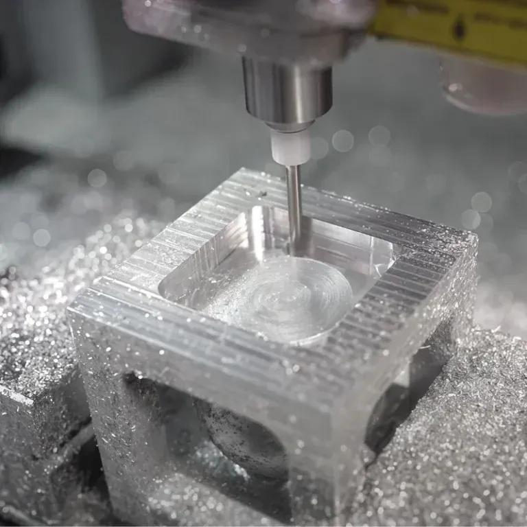
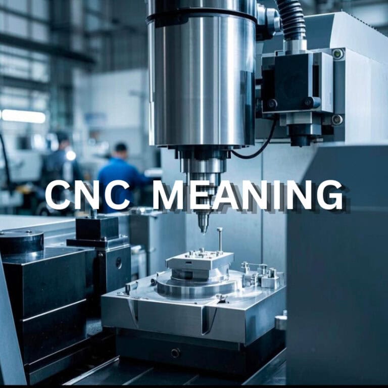
When a wafer processing machine is down for maintenance, the biggest problem is not always a missing large component. Sometimes, a small precision part that does not fit properly can hold up the entire repair. A positioning part with a slightly incorrect hole location or a mounting plate with a small dimensional deviation may require repeated adjustments on site. Semiconductor equipment also has a distinctive requirement: part quantities may be relatively small, but drawings often contain very detailed requirements for materials, hole positions, tolerances, and surface conditions. CNC machining is well suited to this type of customized production, allowing engineering drawings to be converted directly into finished parts for equipment development, upgrades, maintenance, and small-batch production.
What Types of Wafer Equipment Parts Are Commonly CNC Machined?
Semiconductor wafer equipment contains a wide range of structural and functional components. Although these parts vary in size and purpose, they all need to maintain accurate relationships with surrounding components. For purchasing teams, identifying the part type early makes it easier to evaluate machining difficulty and discuss materials, processes, and inspection requirements with the manufacturer.
Wafer Positioning and Support Components
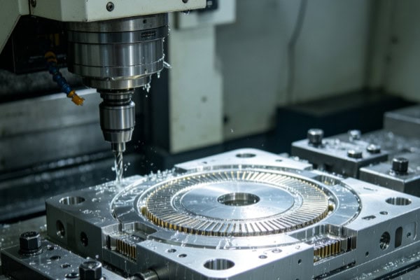
Wafer positioning bases, support components, and related fixtures are mainly used for positioning, supporting, and securing wafers. These parts usually have strict dimensional relationships with other equipment components.
- Positioning holes must remain accurately located.
- Support surfaces require controlled dimensions and flatness.
- Contact edges should be properly deburred.
- Repeated production requires consistent dimensions between batches.
These components may look like relatively simple metal parts, but once installed in the equipment, even small positioning errors can become significant. During CNC machining, datum surfaces, hole locations, and machining sequences need to be planned carefully.
Wafer Transfer Mechanism Components
Wafer transfer systems include guide components, connection bases, mounting blocks, and moving parts. These components need to maintain accurate compatibility with robotic arms, guide rails, and other motion systems.
Such parts commonly contain precision holes, guide grooves, steps, and mounting surfaces. When equipment designs change during development, CNC programs can also be modified quickly, making CNC machining particularly suitable for custom and low-volume semiconductor equipment parts.
Equipment Mounting Plates and Connection Components
Mounting plates, connection bases, and fixing blocks are common structural components in wafer equipment. Their manufacturing requirements often go beyond producing the external shape because they may also contain dense mounting holes and positioning features.
When hole patterns are dense, machining sequence becomes particularly important. Establishing the main datum first, followed by the primary holes and detailed features, can reduce alignment problems during final assembly.
Different part structures, materials, and machining requirements call for different manufacturing approaches. The table below provides a quick overview:
| Part Type | Common Materials | Main Machining Features | Key Machining Focus |
| Wafer positioning base | Aluminum alloy, stainless steel | Positioning holes, support surfaces, steps | Hole location, flatness |
| Wafer support component | Aluminum alloy, PEEK | Surfaces, grooves, mounting holes | Dimensional stability |
| Transfer mechanism part | Stainless steel, aluminum alloy | Guide grooves, connection holes | Fit and alignment accuracy |
| Equipment mounting plate | Aluminum alloy, stainless steel | Dense hole patterns, countersinks, threaded holes | Hole spacing, positional accuracy |
| Fixing bracket | Aluminum alloy, steel | Profiles, holes, slots, mounting surfaces | Structural integrity |
| Precision connection base | Stainless steel, titanium alloy | Threaded holes, positioning surfaces | Connection and assembly accuracy |
When hole patterns become dense, machining sequence becomes increasingly important. Establishing reliable datums before machining critical holes and detailed features helps reduce alignment problems during equipment assembly.
What Are the Main Challenges in CNC Machining Wafer Equipment Parts?
Once the part type has been identified, the actual machining challenges become much clearer. Wafer equipment components often involve fine structures, complex dimensional relationships, and limited machining allowances. A small deviation that might be acceptable for an ordinary mechanical component can cause assembly problems in semiconductor equipment.
Dense Hole Patterns Can Lead to Accumulated Position Errors
A single mounting plate may contain mounting holes, positioning holes, threaded holes, and countersunk holes. Each hole may be relatively simple by itself, but all of them have positional relationships with the main datum and with one another.
- Hole diameters must meet drawing requirements.
- Hole spacing needs to remain consistent.
- Positioning holes must maintain accurate relationships with the datum.
CNC programs provide repeatable tool paths, but datum selection and process sequencing remain critical. The greater the number of holes, the more important it becomes to control their overall positional relationship rather than checking each hole individually.
Small Features Require Careful Tool Control
Wafer equipment components often include narrow grooves, small holes, and fine steps. Oversized tools may not be able to reach these features, while tools with insufficient rigidity can cause vibration or dimensional variation.
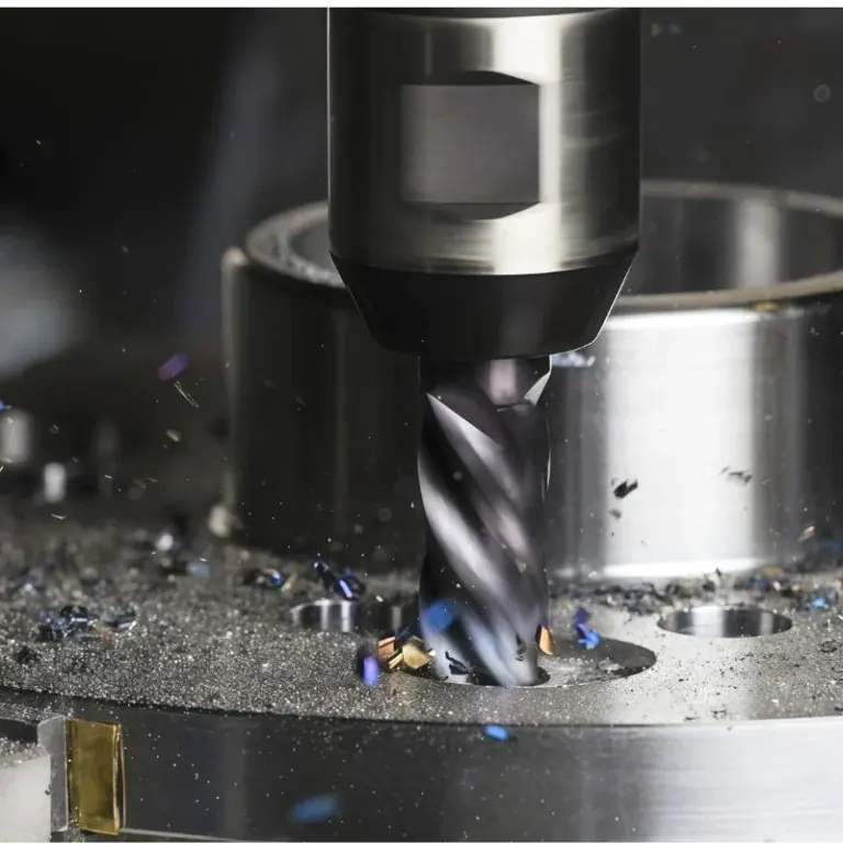
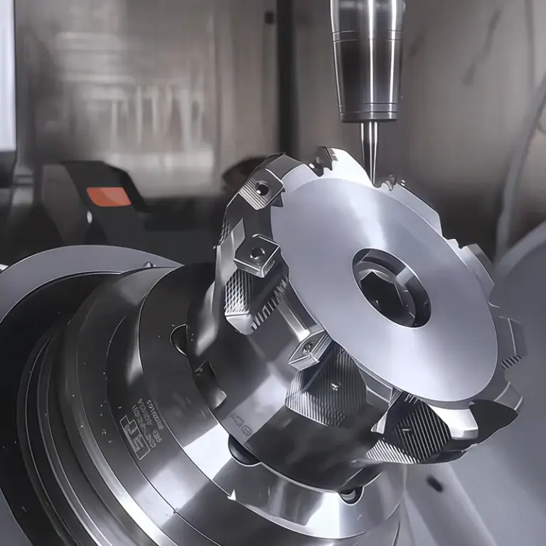
Tool diameter, tool overhang, and cutting parameters need to work together. For particularly small features, it is often better to machine them in several controlled passes rather than attempting to remove too much material in a single cut.
Thin-Wall Components Are Prone to Dimensional Changes
Some equipment components are designed with thin walls to reduce weight or save installation space. During material removal, excessive cutting forces can cause slight deformation.
These parts are often better processed in stages. Major material removal can be completed first, followed by gradual machining of thin-wall areas and critical dimensions. Clamping pressure also needs to be controlled, since excessive clamping force can deform the part before machining even begins.
How Are Different Materials Used for Wafer Equipment Parts Machined?
Material selection is closely related to where the component is used inside the wafer equipment. Aluminum alloys are widely used for lightweight structural components, while stainless steel and titanium alloys can be selected for higher-strength connection parts. PEEK and other engineering plastics may be used in specialized environments. Once the material changes, the tooling, cutting parameters, and machining strategy also need to change.
Aluminum Alloy Parts Require Careful Deformation Control
Aluminum alloys are relatively lightweight and generally offer good machinability, making them suitable for equipment mounting plates, support structures, and other structural components.
For thin-wall parts, large plates, and components requiring substantial material removal, stress and dimensional changes need to be carefully monitored. Removing too much material during rough machining can increase deformation, while leaving a controlled allowance for finishing provides better dimensional stability.
Stainless Steel Parts Require Careful Tool Condition Management
Stainless steel offers good strength and corrosion resistance and is commonly used for connection components and fixing bases.
- Cutting heat needs to be controlled.
- Tool wear should be monitored regularly.
- Chip evacuation is important in deep grooves.
- Finishing operations must control both dimensions and surface quality.
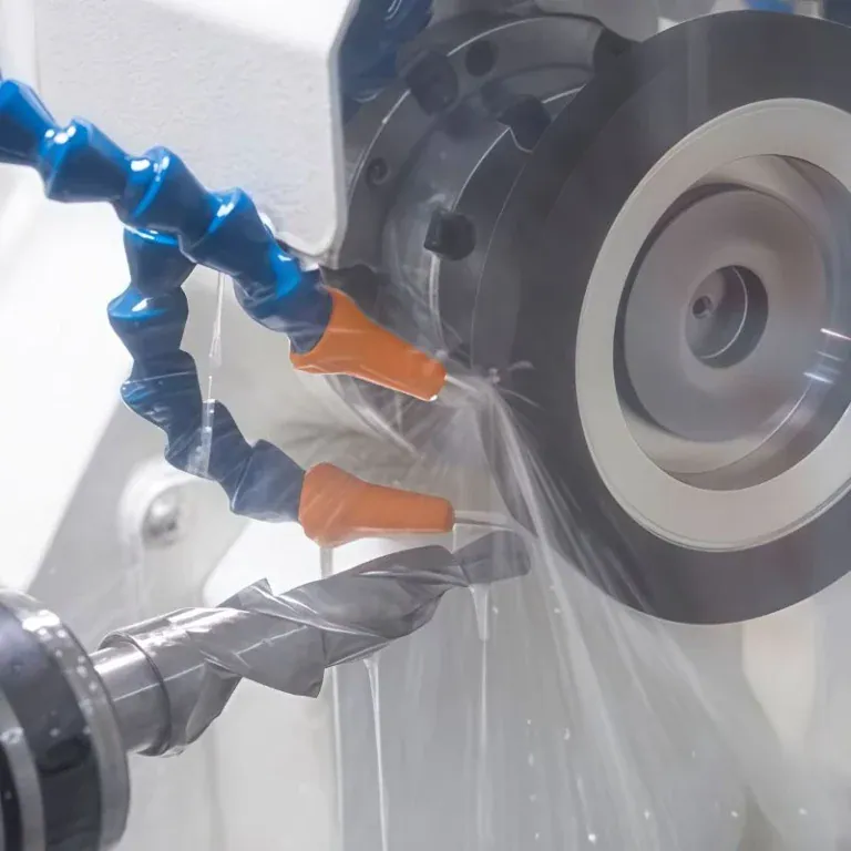
When stainless steel parts contain small holes, threads, and deep grooves at the same time, machining should not be overly aggressive. Stable tool condition makes it easier to maintain dimensional accuracy during the later stages of production.
PEEK and Other Engineering Plastics Require Deformation Control
Some wafer equipment structures use PEEK and other engineering plastics because of their chemical resistance and electrical insulation properties. These materials behave differently from metals during machining.
Excessive clamping force can affect part dimensions, while cutting heat may cause localized dimensional changes. For precision holes and thin-wall areas, clamping pressure, tool sharpness, and machining sequence all require careful control.
How Should CNC Machined Wafer Equipment Parts Be Inspected?
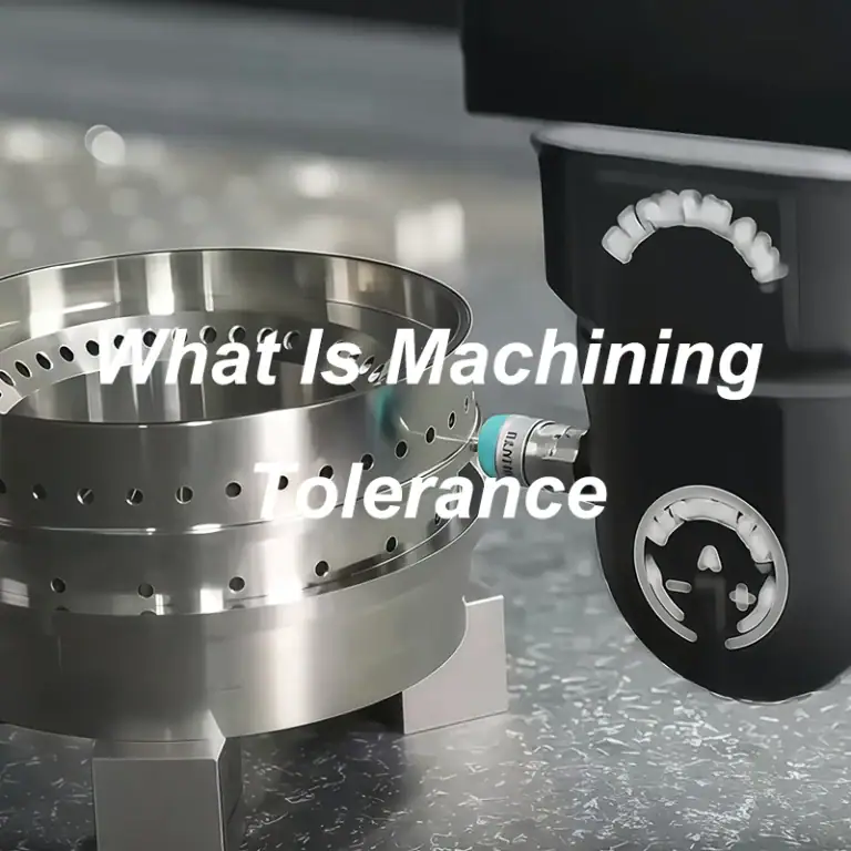
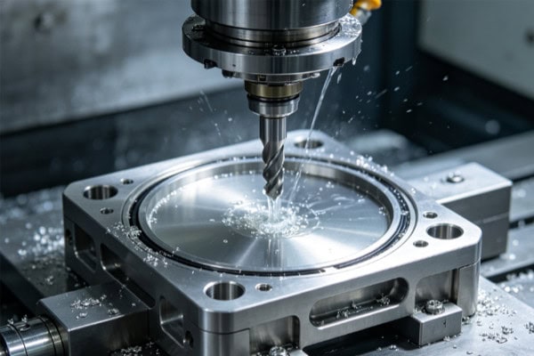
Inspection is the final step that determines whether a machined component is ready for equipment assembly. Purchasing teams should not only check whether the part has been manufactured, but also verify critical dimensions, hole positions, surface condition, cleanliness, and packaging. For long-term supply projects, complete inspection records are also valuable because they make repeat production easier to control.
Critical Dimensions and Hole Locations Need Careful Verification
Inspection priorities vary by part type. Positioning components require close inspection of positioning holes and support surfaces, while mounting plates require attention to hole spacing and installation dimensions. Connection components need accurate thread and mating-area inspection.
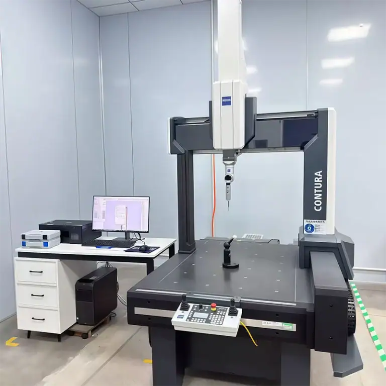
| Inspection Item | Main Check | Common Inspection Method | Key Concern |
| Overall dimensions | Length, width, thickness | Caliper, CMM | Drawing dimensions |
| Positioning holes | Diameter, spacing, location | CMM, gauges | Assembly relationship |
| Mounting surfaces | Flatness, dimensions | CMM | Contact condition |
| Threaded holes | Size, depth, fit | Thread gauge, gauges | Connection performance |
| Grooves | Width, depth | Dedicated gauges | Structural compatibility |
| Surface condition | Burrs, scratches, roughness | Visual inspection, roughness tester | Surface quality |
Recording critical inspection data makes future repeat orders easier to manage and reduces the time required to reconfirm dimensions and machining processes.
Surface Quality Must Match the Application
After CNC machining, surface inspection should go beyond checking for obvious scratches. Burrs, chips, oil, and machining residues also need attention, particularly around wafer transfer, positioning, and precision motion areas.
If the components will eventually be installed in a controlled or clean environment, cleaning and packaging requirements should be confirmed in advance. Proper cleaning after machining, followed by protective packaging, can help reduce contamination and surface damage during transportation.
Batch Production Requires Consistent Quality
A successful prototype does not necessarily mean that future batch production will remain stable. For regularly purchased wafer equipment components, purchasing teams are usually more concerned with whether each production batch can maintain consistent dimensions and quality.
Stable CNC programs, tool management, and inspection records help maintain manufacturing consistency. This makes it easier for delivered parts to move directly into assembly while reducing rework and adjustment time at the equipment site.
CNC machining of semiconductor wafer equipment parts is not simply about turning an engineering drawing into a physical component. The part structure, machining process, material properties, inspection, and delivery requirements all need to work together. Positioning components must maintain accurate relationships, mounting plates need reliable hole positioning, thin-wall parts require deformation control, and specialized materials demand their own machining strategies. Tirapid specializes in CNC machining for semiconductor wafer equipment parts, providing customized precision manufacturing services for different materials, structures, tolerances, and production volumes.