Custom machining is used when a part cannot be sourced as a standard component or when its geometry, material, tolerance, or function must be tailored to a specific project. Instead of forcing a design to fit an existing part, engineers can manufacture the component around the actual mechanical requirements.
This guide explains how custom machining works, why it is useful for complex parts, which processes and materials are commonly used, and how geometry, tolerances, quality requirements, cost, and production volume influence the final manufacturing strategy.
What Is Custom Machining?
Custom machining is the production of parts made to a specific drawing, CAD model, or functional requirement rather than to a standardized catalog specification. These parts may be completely new designs, modified versions of existing components, or replacements for items that are no longer commercially available.
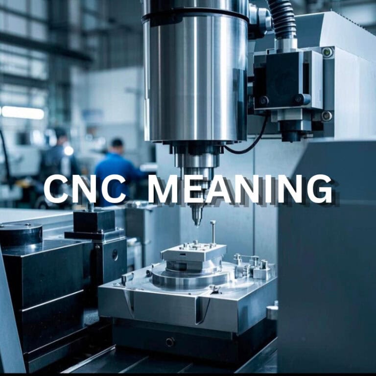
CNC machining is commonly used because its programs, tooling, and setups can be adapted to different geometries without dedicated production molds. Depending on the part, custom machining may involve milling, turning, EDM, drilling, boring, or a combination of several operations.
What Makes a Machined Part Custom?
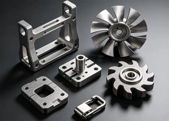
A machined part becomes custom when its specifications are defined for a particular product or application. The difference may involve overall geometry, hole positions, material grade, surface finish, tolerance, engraving, mounting interfaces, or another feature that is not available in a standard component.
Customization does not necessarily mean the part is highly complex. A simple spacer with an unusual diameter or a replacement shaft with a discontinued interface can be just as much a custom machining project as a multi-axis housing with compound surfaces.
Custom Machining vs. Standard Machining
Standardized production is most efficient when the same design is manufactured repeatedly and the process can be optimized around stable geometry. Custom machining gives greater flexibility when part specifications change, quantities are lower, or the geometry requires a project-specific manufacturing strategy.
The distinction is therefore less about which method is more advanced and more about the manufacturing requirement. Stable, repetitive products benefit from optimized production processes, while custom parts benefit from flexible programming, tooling, setup, and engineering review.
Why Custom Machining Works Well for Complex Parts
Complex parts rarely present only one manufacturing challenge. A single component may combine curved surfaces, precise holes, thin walls, deep pockets, different tolerances, and several functional interfaces. Custom machining allows the process to be built around those requirements rather than around a fixed production standard.
Greater Freedom for Unique Geometry
Custom machining gives designers more freedom to create nonstandard shapes because the toolpath is programmed directly from the part geometry. Features do not need to match a catalog size or a pre-existing component.
Multi-axis machining further expands this flexibility by allowing more surfaces to be reached from fewer setups. This is especially useful for housings, brackets, manifolds, impellers, medical hardware, and other parts with features distributed across several faces.
Better Control of Critical Features
A custom part does not need every dimension to receive the same level of precision. Engineers can identify the surfaces that control fit, motion, alignment, sealing, or assembly and assign tighter requirements where they create real functional value.
This allows machining and inspection effort to focus on the features that matter most rather than making the complete part unnecessarily difficult to manufacture.
Flexible Production Without Dedicated Tooling
One of the main advantages of custom CNC machining is that design changes can often be handled by updating the CAD model, program, toolpath, fixture, or machining strategy instead of creating a new mold or die.
That flexibility is particularly useful during prototyping and low-volume production, where the design may still change and dedicated production tooling would be difficult to justify.
How Does the Custom Machining Process Work?
A reliable custom machining process starts before material reaches the machine. The drawing, geometry, tolerance, material, production quantity, and inspection requirements all affect how the part should be manufactured.
Review the CAD Model and Technical Drawing
The first step is to review the CAD model and drawing for dimensions, tolerances, materials, finishes, threads, datum relationships, and other specifications.
Manufacturability should also be checked at this stage. Deep cavities, inaccessible internal features, very thin walls, unusual corner radii, and unnecessarily tight tolerances can make a part significantly harder to machine.
Select the Process, Material, and Tooling
The manufacturing method depends on the shape of the component. Rotational geometry may favor turning, prismatic features often favor milling, and parts combining both may require multiple processes.
Tool selection must also account for material behavior, feature depth, access, rigidity, and surface requirements. Some projects can be completed with standard tools, while complex geometry may need specialty cutters or EDM.
Program, Machine, and Finish the Part
CAM programming converts the required geometry into machining operations and toolpaths. The process may include roughing, semi-finishing, drilling, threading, finishing, and additional setups.
After machining, parts may require deburring, polishing, anodizing, plating, passivation, heat treatment, or another secondary process depending on the application.
Inspect the Final Component
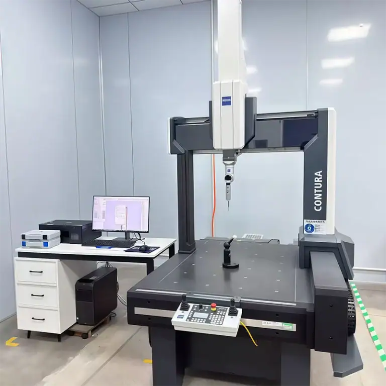
Inspection verifies that the manufactured part meets the drawing and functional requirements. The inspection method should match the feature being measured rather than relying on one instrument for every dimension.
Calipers and micrometers work well for many accessible dimensions, while complex profiles, positions, and datum relationships may require coordinate measurement or optical methods.
Main Custom Machining Processes
Custom machining is not one specific operation. The best process depends on whether the part is rotational, prismatic, multi-sided, highly contoured, or difficult to reach.
CNC Milling
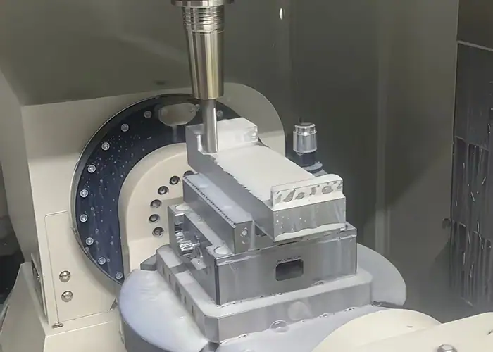
CNC milling uses rotating cutting tools to remove material from a stationary or indexed workpiece. It is commonly used for pockets, slots, flat surfaces, hole patterns, contours, brackets, housings, fixtures, and other prismatic components.
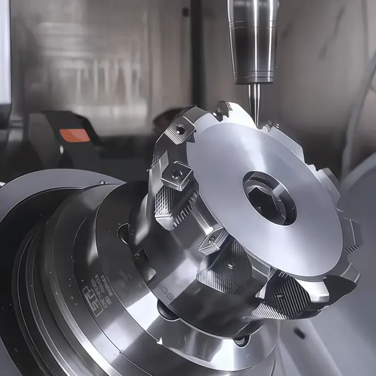
Three-axis milling handles many conventional parts efficiently, while four-axis and five-axis machines provide additional access when features are located on multiple sides or at compound angles.
CNC Turning
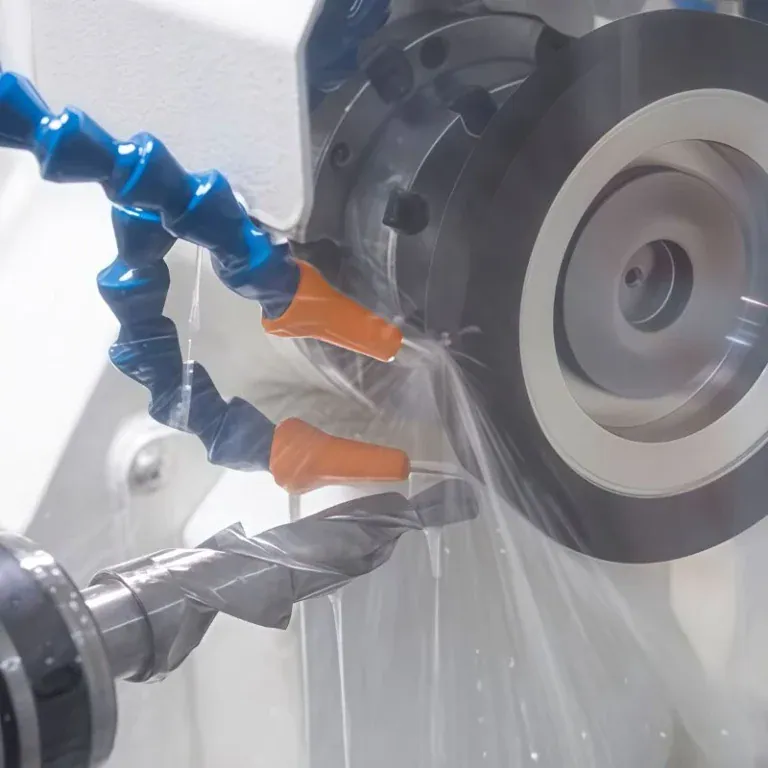
CNC turning rotates the workpiece while a cutting tool removes material. It is particularly effective for shafts, bushings, pins, sleeves, threaded components, and other parts based mainly on cylindrical geometry.
Turn-mill equipment can combine turning with milling, drilling, and other operations, which can reduce transfers between machines for suitable components.
5-Axis CNC Machining
5-axis machining allows the tool to approach the workpiece from additional orientations. It is valuable for complex surfaces, multi-sided parts, angled features, and components that would otherwise require several repositioning operations.
The main manufacturing benefit is not simply greater complexity. A better approach angle can also allow shorter, more rigid tools and reduce the number of setups required.
EDM and Secondary Machining
Electrical discharge machining is useful for electrically conductive materials when conventional cutting tools cannot efficiently create narrow slots, sharp internal details, small features, or difficult internal geometry.
Custom projects may also combine machining with grinding, honing, reaming, welding, heat treatment, or surface finishing when the final requirements cannot be achieved in one operation.
What Materials Can Be Used for Custom Machining?
Custom machining supports a broad range of metals and engineering plastics. The correct material should be selected for the part’s function first, then the machining strategy should be adjusted around its strength, hardness, thermal behavior, stability, and machinability.
Aluminum and Aluminum Alloys
Aluminum is widely used because it combines relatively low density with good machinability. Grades such as 6061 are common for housings, fixtures, brackets, prototypes, and general precision components, while higher-strength grades such as 7075 may be selected where mechanical performance is more demanding.
Its high thermal conductivity helps move heat away from the cutting zone, although thin features and burr formation still require careful control.
Steel and Stainless Steel
Carbon and alloy steels provide strength, wear resistance, and a wide range of heat-treatment options. Stainless steels add corrosion resistance and are common in equipment, medical, processing, and fluid-handling applications.
Compared with aluminum, many steels create higher cutting forces and greater tool wear. Stainless grades can also require more attention to heat generation and work hardening.
Titanium and Other High-Performance Metals
Titanium is selected when high strength-to-weight ratio, corrosion resistance, or demanding service performance justifies the added machining difficulty.
Its relatively low thermal conductivity concentrates heat near the cutting edge, making tool wear, cooling, and cutting stability important considerations.
Engineering Plastics
Engineering plastics such as POM, PEEK, PTFE, nylon, and PEI are used for insulators, bushings, wear components, lightweight structures, chemical-resistant parts, and other specialized applications.
Their machining behavior differs significantly from metals. Heat, clamping force, moisture absorption, thermal expansion, and material flexibility can all influence final dimensions.
Machining Challenges in Complex Custom Parts
Complexity becomes difficult when geometry restricts tool access, reduces part rigidity, increases the number of setups, or makes inspection harder. The best strategy is therefore to evaluate how the part will actually be cut and measured, not just whether the geometry can be modeled.
Deep Pockets and Internal Features
Deep pockets often require long-reach tools. As tool overhang increases, rigidity decreases and the cutter becomes more sensitive to vibration and deflection.
Internal corners also need realistic radii because rotating cutters cannot create perfectly sharp internal corners directly. Designing around available cutter sizes can improve both stability and cost.
Thin Walls and Delicate Structures
Thin walls can move under cutting and clamping forces. Removing material also reduces stiffness as machining progresses, so the geometry may behave differently during roughing and finishing.
Manufacturing strategies may include staged material removal, support features, lighter finishing passes, controlled fixturing, and appropriate cutting direction.
Multi-Sided and Contoured Geometry
Features positioned on several sides may require multiple setups on a conventional machine. Every repositioning operation introduces another opportunity for alignment variation.
Multi-axis machining can reduce these transitions for suitable parts and provide better access to compound surfaces and angled features.
Features Requiring Multiple Operations
Some parts combine turned diameters, milled pockets, drilled holes, precision bores, threads, and surface treatments.
The main challenge is maintaining datum relationships across operations. Process planning should establish which features are created first and how later setups locate the part.
Tolerances and Precision in Custom Machining
Custom machining can support close dimensional control, but achievable tolerance depends on material, geometry, feature size, machine capability, tooling, workholding, thermal stability, and inspection. It should therefore be defined according to function rather than as one universal number.
Which Dimensions Need Tight Tolerances?
Critical dimensions usually control mating relationships, bearing fits, sealing, alignment, positioning, or motion. These deserve greater manufacturing and inspection attention.
Non-functional clearance surfaces often do not require the same precision. Relaxing unnecessary tolerances can reduce machining time and simplify inspection without reducing part performance.
How Setup and Tooling Affect Accuracy
Tool length, cutter stiffness, workholding, machine condition, tool wear, and cutting strategy all influence dimensional consistency.
Setup design is particularly important when several surfaces reference one another. Keeping related features in a common setup can reduce repositioning error where the geometry allows it.
Managing Tolerance Stack-Up
A single component may meet every individual dimension yet still create an assembly issue if several tolerances accumulate in the same direction.
Clear datums and functional dimensioning help control this risk. Designers should focus on the chain of dimensions that affects the actual interface rather than tightening every feature independently.
Design for Better Custom Machining
Good design for custom machining does not mean simplifying every part. It means keeping the required function while avoiding geometry that adds cost without improving performance.
Improve Tool Access and Workholding
Every machined feature needs a practical approach path for both the cutter and the complete tool assembly.
Parts should also provide enough stable geometry for fixturing. A feature that is easy to model but difficult to clamp may require additional setups or custom workholding.
Use Practical Radii, Depths, and Wall Thicknesses
Larger internal radii generally allow more rigid tools and easier machining. Moderate pocket depths reduce the need for excessive tool reach, while practical wall thicknesses improve stability.
These decisions can have a larger effect on manufacturability than small changes to overall part dimensions.
Simplify Features That Add Unnecessary Complexity
Very deep slots, hidden pockets, nonstandard threads, sharp internal corners, and cosmetic surfaces with demanding tolerances can add operations.
When these features have no clear functional purpose, simplifying them can reduce cycle time, special tooling, and inspection requirements.
Apply Tight Tolerances Only Where They Matter
A drawing becomes harder and more expensive to manufacture when close tolerances are applied broadly.
The more effective approach is to identify which dimensions control function and leave reasonable manufacturing freedom elsewhere.
How Quality Is Controlled in Custom Machining
Quality control should be integrated into the manufacturing process rather than treated only as a final check. Complex parts benefit from confirming critical dimensions before additional operations make rework difficult.
First Article and In-Process Inspection
First article inspection verifies that the initial manufacturing process produces the required dimensions, material condition, and finish before additional parts are completed.
In-process checks can then monitor critical dimensions, tool wear, setup consistency, and other variables during production.
Dimensional Inspection for Complex Features
Different geometries require different inspection methods. Coordinate measuring machines are useful for complex geometry and datum-based measurements, while optical systems can be useful for visible profiles and small features.
Inspection planning should be considered during design because deeply recessed or hidden features can be difficult to measure even when they are machinable.
Surface Finish and Final Verification
Surface quality can affect sealing, wear, friction, appearance, fatigue behavior, or coating performance.
Final verification should therefore confirm both dimensional requirements and specified finish conditions before the part is released.
What Affects Custom Machining Cost and Lead Time?
Custom machining cost is driven by the complete manufacturing route. Material price matters, but machining time, setup complexity, tooling, inspection, finishing, and quantity often have just as much influence.
Part Geometry and Machining Time
Complex geometry can require more toolpaths, smaller cutters, slower finishing passes, multiple setups, or additional programming.
Deep features and restricted access also tend to increase cycle time because cutting conditions must remain stable.
Material and Machinability
Material affects both raw stock price and machining effort. Aluminum usually machines more easily than titanium or many stainless steels, while harder or heat-resistant materials can increase cutting time and tool consumption.
Material grade and certification requirements can also influence procurement and lead time.
Tolerances and Surface Requirements
Tighter tolerances may require more stable setups, extra finishing passes, environmental control, and additional inspection.
Specified roughness, polishing, heat treatment, anodizing, plating, or passivation can add further production stages.
Quantity and Secondary Operations
Small quantities carry programming and setup costs across fewer parts, while larger quantities allow those costs to be distributed more efficiently.
Secondary processes can also affect scheduling because parts may need to move between machining, finishing, heat treatment, and inspection suppliers.
When Does Custom Machining Make Sense?
Custom machining is most valuable when flexibility, geometry, or production quantity makes standardized solutions impractical. Common situations include unique designs, replacement parts, prototypes, and precision components produced in modest quantities.
Prototypes and New Product Development
CNC machining allows functional parts to be produced directly from engineering data without dedicated molds.
Designs can therefore be tested and revised before higher-volume tooling or production decisions are made.
Low-Volume Precision Production
Low-volume parts often need production-quality materials and accurate geometry but do not justify high tooling investment.
Custom machining fits this requirement because programming and fixturing can be adapted to the specific quantity without requiring a permanent production tool.
Nonstandard and Replacement Parts
Older equipment may use components that are discontinued or unavailable from the original supplier.
A replacement can sometimes be manufactured from an existing drawing, CAD model, sample, or reverse-engineered geometry, allowing critical equipment to remain in service.
Parts With Unique Functional Requirements
A standard component may be close to the required design but still fail because of one interface, material, hole pattern, tolerance, or environmental requirement.
Custom machining allows that feature set to be built around the application instead of redesigning the surrounding assembly to accommodate an unsuitable standard part.
Custom Machining vs. Other Manufacturing Methods
Custom machining is especially competitive for precision parts, complex geometry, prototypes, and lower production quantities because it avoids dedicated production tooling. Other methods may become more suitable when geometry or volume changes.
Custom Machining vs. Injection Molding
Machining is more flexible for prototypes and low-volume parts because no mold is required. Injection molding becomes more attractive when a plastic design is stable and production volume is high enough to justify tooling.
Custom Machining vs. 3D Printing
Machining produces parts directly from engineering-grade stock and is well suited to accurate functional surfaces. 3D printing offers greater freedom for highly complex internal geometry and can be useful for rapid concept development.
Custom Machining vs. Casting
Machining is often simpler for lower quantities and precision features. Casting becomes more competitive for suitable shapes and higher production volumes but generally requires tooling and may still need secondary machining on critical surfaces.
FAQs
How Much Does Custom Machining Cost?
Custom machining cost depends on part geometry, material, tolerance, quantity, machining time, surface finish, and inspection requirements. Simple aluminum parts may be relatively economical, while complex geometries, difficult materials, tight tolerances, and multiple secondary operations usually increase the total cost.
Why Is CNC So Expensive?
CNC machining can become expensive because the price includes more than material removal. Programming, machine setup, fixtures, cutting tools, machining time, tool wear, inspection, and finishing all contribute to the final cost. Complex parts and tight tolerances usually require additional operations and quality control.
Where To Find Rapid CNC Machining Services For Custom Parts?
Choose a supplier that can support your required materials, tolerances, part complexity, inspection, and delivery schedule. At TiRapid, we provide precision CNC machining services for custom metal and engineering plastic parts, supporting prototypes and low-volume production with milling, turning, multi-axis machining, and dimensional inspection.
Conclusion
Custom machining makes complex parts easier to produce by allowing the manufacturing process to adapt to the actual geometry, material, tolerance, and quantity required. Its value is strongest when standard components cannot satisfy the design, when prototypes need frequent revision, or when precise low-volume parts must be produced without dedicated tooling. Good results depend on practical feature design, stable machining strategies, appropriate tolerances, and inspection focused on the dimensions that control function.
At TiRapid, we provide precision CNC machining and manufacturing services for custom metal and engineering plastic parts. Our capabilities support CNC milling, turning, multi-axis machining, complex geometries, dimensional inspection, surface finishing coordination, prototypes, and low-volume production.