
Boring machining is a precision cutting process used to enlarge and correct an existing hole. Unlike drilling, which creates the initial hole, boring improves diameter, roundness, straightness, alignment, and internal surface quality when the original hole cannot meet the final functional requirements.
This guide explains the boring machining process, common methods and tools, hole tolerances, factors that affect accuracy, suitable materials, applications, and the differences between boring, drilling, and reaming. It also covers common machining problems and how to choose an efficient method for precision bores.
What Is Boring Machining?
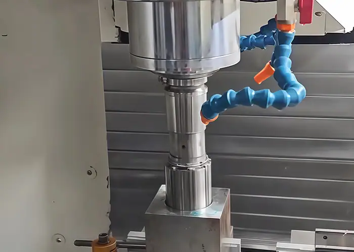
Boring removes material from the inside of a pre-existing hole using a single-point cutting tool, typically mounted on a boring bar. The starting hole may be drilled, cast, forged, or produced by another machining operation. A lathe, milling center, jig borer, or dedicated boring machine can then enlarge and refine it to the required size and geometry.
The main value of boring is not simply making a hole larger. It allows the machinist to correct geometry and establish a more controlled relationship between the bore and other functional features on the part.
What Does Boring Improve?
Boring primarily improves hole diameter, roundness, straightness, alignment, and surface quality. These characteristics often matter more than nominal diameter alone when the bore accepts a bearing, bushing, shaft, seal, guide, or other precision component.
A drilled hole may be close to the required size but still have taper, runout, or positional error. A controlled boring pass removes material relative to the machine spindle and established datum, allowing the final bore to better match its intended axis and geometry.
Internal finish is equally important. Bearing seats, sliding fits, and sealing surfaces need consistent contact conditions, so a stable boring operation can provide a more uniform surface than a rough drilled or cast hole.
When Is Boring Machining Needed?
Boring is appropriate when an existing hole is undersized, out of round, misaligned, or not accurate enough for the final assembly. It is also useful when a cast or forged opening contains enough machining allowance to establish a controlled finished bore.
Typical examples include bearing housings, gearbox bores, hydraulic components, motor housings, engine components, and precision tooling. In each case, the need for boring comes from the functional requirement of the hole rather than from the hole diameter alone.
For a simple clearance hole with a loose tolerance, drilling may already be sufficient. Adding boring where it provides no functional improvement only increases machining time and cost.
How Does The Boring Machining Process Work?
The exact boring machining process depends on bore depth, diameter, material, starting condition, and final tolerance. Simple parts may need only one corrective pass, while precision components can require rough, semi-finish, and finish boring.
A practical boring process starts by establishing the hole and its machining datum, then progressively corrects size and geometry before the final inspection.
Hole Preparation And Setup
The initial opening may come from drilling, casting, forging, or rough machining. Before boring begins, the workpiece must be located from a suitable datum and clamped securely.
Setup accuracy is critical because the boring tool follows the machine’s programmed axis. If the workpiece datum or setup is incorrect, the bore may reach the correct diameter but still be incorrectly positioned relative to bearing seats, mating faces, bolt patterns, or other features.
The starting hole must also contain enough stock for the boring tool to clean up the surface and correct the intended geometry. Boring can improve alignment only when sufficient material remains to establish the new bore.
Rough And Semi-Finish Boring
Rough boring removes the majority of excess material. It is useful for correcting cast surfaces, removing substantial machining allowance, and bringing an irregular initial hole closer to the required geometry.
For tighter requirements, a semi-finish pass can leave a more uniform allowance before final boring. This reduces the amount of material removed during the final pass and helps stabilize cutting forces.
The objective is not to make every stage equally precise. Roughing creates the basic condition, while later passes progressively reduce geometric and dimensional variation.
Finish And Precision Boring
Finish boring removes a small amount of material to establish final diameter, alignment, and internal surface quality. Because the cut is light, tool rigidity, machine stability, offset control, and vibration become especially important.
Precision boring is commonly used for bearing seats, shaft-support bores, sealing areas, and other fitted components. Stable CNC equipment and fine boring tools can hold tight hole tolerances, although the achievable result always depends on bore geometry, material, tool reach, thermal stability, and machine condition.
The final pass should therefore be planned around the functional requirement rather than an arbitrary tolerance target.
Main Types Of Boring Machining
There are many types of boring machine, but most production decisions are better understood by looking at workpiece size, orientation, bore depth, access, and required positional accuracy.
The goal is to choose a configuration that supports the workpiece and tool rigidly while giving the cutting tool reliable access to the bore.
Horizontal And Vertical Boring
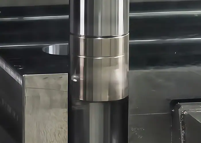
Horizontal boring machining positions the spindle horizontally and is particularly useful for large housings, machine structures, long bores, and components with several internal features. The arrangement allows large workpieces to remain supported while the spindle or table controls the cutting position. Horizontal and vertical boring are both established approaches for large and precision work.
Vertical boring is often more suitable for large, heavy parts that are easier to support on a horizontal table. Gravity helps keep the workpiece seated, which can simplify the handling of large circular or housing-type components.
In practice, boring mill machining is often selected for large castings, gearboxes, equipment frames, and similar parts where bore accuracy must be maintained across substantial workpiece dimensions.
Precision And Jig Boring
Precision boring focuses on achieving controlled diameter, geometry, and surface finish. It is used when a conventional rough hole cannot satisfy the drawing requirements directly.
Jig boring places additional emphasis on hole location and the positional relationship between features. It is useful for tooling, fixtures, mold components, precision housings, and parts where several holes must be accurately located relative to defined datums.
The distinction is therefore functional: precision boring concentrates on bore quality, while jig boring is particularly valuable when precise location is also critical.
Line, Back And Specialty Boring
Line boring is used when two or more bores need to share a common axis. Bearing supports in machinery, equipment housings, and large structural assemblies are typical examples.
Back boring allows a feature to be machined on the far side of an existing opening when direct access from that side is limited. Blind boring and micro boring address other specific geometric requirements.
These methods are useful, but they should be selected because of access, alignment, or geometry needs rather than treated as interchangeable versions of the same operation.
Tools Used In Boring Machining
Boring accuracy depends heavily on the cutting system. The tool must reach the required depth without excessive bending while maintaining a stable cutting edge against the bore surface.
For most CNC work, the key elements are the boring bar, boring head or adjustment system, cutting insert, and suitable inspection equipment.
Boring Bars And Boring Heads
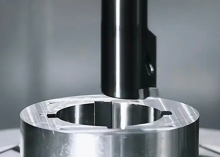
A boring bar supports the cutting edge inside the hole. Its diameter, material, length, and unsupported overhang directly affect stiffness.
Long overhang is one of the most common causes of poor boring performance. As the unsupported length increases, the bar becomes more susceptible to elastic deflection and vibration, which can produce taper, inconsistent diameter, and chatter marks.
The bar should therefore be as large and as short as the bore geometry permits. Fine boring heads can provide controlled diameter adjustment for finishing operations where small offset changes have a meaningful effect on final size.
Cutting Inserts
Insert selection depends on workpiece material, cutting load, bore geometry, and finish requirement.
Sharp, positive cutting geometry can reduce radial cutting forces, which is useful when the boring bar has limited rigidity. More demanding materials may require wear-resistant carbide grades or coatings to maintain a consistent cutting edge.
The objective is not simply maximum tool life. A boring insert must also generate predictable cutting forces so that tool deflection and bore size remain stable throughout the operation.
Measuring And Inspection Tools
Bore diameter can be checked with bore gauges, inside micrometers, or appropriate coordinate measurement equipment. The correct method depends on bore size, tolerance, depth, and drawing requirements.
Diameter measurement alone is not always sufficient. A precision bore may also require verification of position, runout, roundness, straightness, or alignment with another bore.
Inspection should therefore reflect the functional specification rather than measuring only the easiest characteristic.
Boring Machining Tolerances And Hole Accuracy
A precision bore cannot be defined by one diameter tolerance alone. Its function may depend on size, roundness, straightness, position, alignment, and surface finish working together.
This is especially important for bearing and shaft interfaces, where a bore can be dimensionally correct yet still cause assembly or rotational problems if its geometry is poor.
Hole Diameter And Fit Tolerance
The required hole tolerance depends on what will be assembled into the bore. Bearings, bushings, pins, shafts, and press-fit components all impose different fit requirements.
Clearance, transition, and interference fits should therefore be selected from actual assembly conditions, load, temperature, material, and service requirements.
CNC boring can achieve tight diameter control under stable conditions. However, applying the tightest possible tolerance to every bore is rarely economical. Critical fit surfaces deserve close control. general clearance holes often do not.
Roundness And Straightness
A hole produced by drilling can contain taper, wander, or out-of-round geometry. Casting can introduce additional variation because the original opening may not be perfectly located or shaped.
Boring removes material along a more controlled cutting path and can improve these conditions. For deep holes, however, tool reach becomes increasingly important because bar deflection can cause the diameter to change along the bore length.
Roundness and straightness should therefore be considered separately from diameter. A gauge reading at one location cannot confirm that the entire bore has acceptable geometry.
Hole Alignment And Coaxiality
Alignment becomes critical when several bores support the same rotating shaft or when a bore must relate accurately to another datum feature.
Because a boring tool cuts relative to the machine axis, it can correct some errors in the starting hole if sufficient stock remains. This makes boring particularly useful for bearing housings, gearbox components, motor housings, and multi-bore assemblies.
Where several bores must share a common functional axis, setup strategy is often as important as the nominal hole size.
Surface Finish Inside The Bore
Internal surface finish affects friction, bearing contact, sealing, sliding behavior, and wear.
A smooth finish is not automatically better for every application. The required roughness should be specified according to the bearing, bushing, seal, lubrication condition, or other functional interface.
Finish boring can provide a controlled surface when the cutting system remains stable. If the functional requirement exceeds what boring can economically achieve, another finishing operation such as honing or grinding may be considered.
Key Factors Affecting Boring Accuracy
Boring accuracy is strongly influenced by stiffness and process stability. Machine capability matters, but an accurate CNC machine cannot compensate for an excessively flexible boring bar or unstable workholding.
The most important variables are tool overhang, cutting conditions, machine rigidity, thermal behavior, chip evacuation, and setup quality.
Tool Rigidity And Overhang
A boring bar behaves like a cantilever. Extending it farther from the holder reduces stiffness and increases the amount it can deflect under cutting force.
This is why deep bores are more difficult than shallow bores of the same diameter. A small amount of bar movement can change the effective cutting radius and therefore change the finished diameter.
Using the largest practical bar diameter, minimizing unsupported length, and selecting a stiffer or vibration-damped bar when required can improve consistency.
Cutting Speed, Feed And Depth Of Cut
Cutting speed, feed, and depth of cut affect material removal, cutting force, heat, vibration, surface finish, and tool life.
Aggressive roughing conditions may be appropriate when stock must be removed efficiently, but finish boring needs a more stable cutting condition. Excessive radial load can deflect the boring bar, while an unstable speed range can encourage chatter.
There is no universal set of parameters for boring. Material, tool geometry, bar stiffness, machine power, and bore dimensions must be considered together.
Machine Stability, Coolant And Chip Control
Rigid workholding and stable spindle motion help maintain the intended relationship between the tool and bore.
Coolant can control temperature and assist chip removal, particularly in deeper holes where chips have fewer paths to escape. Poor evacuation can allow chips to recut against the finished wall, damaging surface quality or accelerating tool wear.
Thermal consistency also matters when tolerances become tight. Tool, spindle, and workpiece temperature changes can shift dimensions enough to affect final bore size.
Materials Suitable For Boring Machining
Boring can be used on a wide range of metals and engineering plastics. The process principle remains similar, but material behavior changes cutting forces, heat generation, tool wear, burr formation, and achievable surface quality.
The table below summarizes common considerations.
| Material | Machining Characteristic | Key Boring Consideration |
| Aluminum | Good machinability | Built-up edge and surface quality |
| Carbon / Alloy Steel | Strong, widely used | Cutting force and tool wear |
| Stainless Steel | Corrosion resistant | Work hardening and heat control |
| Cast Iron | Dimensionally stable but abrasive | Tool wear and chip control |
| Titanium | High strength-to-weight ratio | Heat concentration and tool life |
| Brass / Copper | Good functional properties | Burr formation and material behavior |
| Engineering Plastics | Lightweight and corrosion resistant | Heat and deformation |
Aluminum generally allows efficient material removal, but tool sharpness and chip control still affect finish. Steel and alloy steel require greater attention to cutting force and insert wear, while stainless steel can work harden if the cutting edge rubs rather than cuts cleanly.
Cast iron is commonly bored in housings and machine components, but its abrasive nature can accelerate tool wear. Titanium concentrates heat near the cutting zone, making stable tooling and heat management particularly important.
Engineering plastics can also be bored accurately, although heat and clamping pressure must be controlled to limit deformation.
Advantages And Limitations Of Boring Machining
Boring is highly effective when an existing hole needs better size, geometry, or alignment. It is less useful when a drilled hole already meets the drawing or when the required geometry is poorly suited to a single-point internal tool.
A practical evaluation should consider both capability and added machining time.
| Advantages | Limitations |
| Accurate final hole sizing | Requires an existing opening |
| Can correct some hole alignment errors | Sensitive to tool deflection |
| Improves roundness and straightness | Deep bores are more difficult |
| Good control of internal finish | Precise setup adds machining time |
| Adjustable finished diameter | Not ideal for every hole geometry |
One major advantage is adjustability. Unlike a fixed-size drill or reamer, a boring tool can be adjusted to target a specific final diameter.
Its main limitation is stiffness. The cutting edge must extend inside the workpiece, so deep or small-diameter holes can restrict bar size and increase vibration risk.
Boring Vs Drilling Vs Reaming
Drilling, boring, and reaming all machine holes, but they solve different problems. Treating them as interchangeable can add unnecessary operations or leave important geometry uncontrolled.
The basic distinction is simple: drilling creates the initial hole, boring corrects and enlarges it, and reaming performs light final sizing when the starting hole is already reasonably accurate.
| Process | Main Purpose | Stock Removal | Geometry Correction | Typical Role |
| Drilling | Create a hole | Higher | Limited | Initial hole creation |
| Boring | Enlarge and correct | Moderate | Strong | Size and axis correction |
| Reaming | Fine-size an existing hole | Low | Limited | Final sizing and finish |
When Should You Choose Boring Instead Of Reaming?
The boring vs reaming decision depends mainly on the condition of the existing hole.
Boring is usually the better choice when significant stock must be removed or when size, straightness, position, or alignment needs correction. Because the boring tool follows a controlled axis and has an adjustable cutting radius, it can establish geometry rather than simply following the original hole.
Reaming is more appropriate when the hole is already correctly positioned and close to final size. It removes relatively little material and is effective for improving final diameter and finish.
Common Problems In Boring Machining
Most boring problems are symptoms of instability, tool deflection, incorrect adjustment, heat, or poor setup. Recognizing the pattern of the error helps identify its likely cause.
The three most common concerns are chatter, dimensional taper, and alignment error.
Chatter And Poor Surface Finish
Chatter occurs when the tool and workpiece enter a self-excited vibration. On the finished bore, it can appear as repeating marks, waviness, noise during cutting, and inconsistent roughness.
Excessive boring-bar overhang is a common cause, although spindle condition, workholding, insert geometry, and cutting parameters can also contribute.
Improving stiffness and stabilizing cutting conditions usually produces a better result than simply adding another finishing pass over an unstable setup.
Taper And Oversized Bores
A bore that changes diameter from entrance to depth may indicate tool deflection, thermal movement, bar instability, or cutting-edge wear.
The problem can be more pronounced in deep holes because the boring bar needs greater reach. Even if the machine follows the programmed path accurately, a flexible tool can move under cutting load.
Oversized bores may also result from incorrect tool adjustment, offsets, insert movement, or thermal conditions. For tight fits, tool offsets and measurement feedback must therefore be controlled carefully.
Misalignment And Position Error
A hole can have the correct diameter and still fail if its centerline is incorrectly located.
Datum selection, fixture positioning, spindle alignment, and previous machining operations all affect final bore position. This becomes particularly important when the bore must align with another bearing seat or rotating component.
For multi-bore housings, manufacturing strategy should prioritize the relationship between bores rather than treating each diameter as an independent feature.
Applications Of Boring Machining
Boring is most valuable where an internal hole performs a real mechanical function. Bearing support, sealing, guided motion, rotational alignment, and precision assembly all create stronger requirements than an ordinary clearance hole.
For that reason, the process appears across automotive, industrial, aerospace, medical, and energy-related equipment.
Automotive
Engine blocks, transmission housings, bearing locations, axle components, and other powertrain parts can contain bored features.
These components often require the bore to control not only diameter but also alignment with adjacent rotating or sliding features.
Reliable geometry supports correct bearing fits, piston movement, shaft alignment, and assembly consistency.
Industrial Equipment
Gearboxes, pumps, hydraulic components, machine frames, compressors, and motor housings commonly contain precision bores.
Industrial equipment may operate continuously under significant load, so small alignment errors can contribute to vibration, uneven bearing loading, seal wear, or reduced service life.
Large housings are also a common application for horizontal boring and boring mills because the machine arrangement can accommodate substantial part sizes.
Medical
Some medical devices and mechanical medical equipment contain small or precision internal features that require controlled diameter and finish.
Material compatibility, cleanliness, traceability, and specific product requirements remain important. Boring capability alone does not determine whether a component is suitable for medical use.
The process is therefore applied selectively where accurate internal geometry is functionally necessary.
Aerospace
Aerospace housings, structural components, actuation systems, and rotating assemblies may require accurately located bores for bearings, pins, shafts, or other interfaces.
The challenge is often the combination of tight geometry with materials such as titanium, stainless steel, or high-strength alloys.
Here, tool rigidity and thermal control become particularly important because difficult-to-machine materials increase cutting forces and tool wear.
Oil & Gas
Valve bodies, pump components, pressure-system parts, and other energy equipment can contain large or deep bores where sealing, alignment, and dimensional control matter.
The materials may also be relatively hard or corrosion resistant, increasing the importance of tool selection and process stability.
In these applications, the finished internal geometry should be evaluated together with pressure, sealing, material, and service-environment requirements.
What Affects Boring Machining Cost?
Boring cost is driven by the difficulty of producing and verifying the required bore, not simply by diameter. Depth, material, tolerance, tool reach, surface finish, setup, inspection, and production volume all influence machine time.
A clear drawing that identifies genuinely functional requirements makes process planning more efficient.
Bore Size And Depth
A large accessible bore may be relatively straightforward even when its diameter is substantial.
A deep, narrow bore can be more difficult because the tool must extend farther from its support. Greater overhang reduces stiffness, complicates chip evacuation, and increases the likelihood of vibration or taper.
This is why bore depth can have as much influence on cost as diameter.
Tolerance And Surface Finish
Tighter tolerances require greater control over tooling, temperature, offsets, and inspection.
A precision bearing bore may require roughing, semi-finishing, fine boring, and detailed measurement. A non-critical clearance hole may need only drilling.
The most cost-effective approach is therefore to apply demanding requirements only where they affect fit, alignment, sealing, wear, or other measurable functions.
Material And Production Volume
Harder or abrasive materials can increase cutting time and tool consumption, while heat-sensitive or difficult-to-machine materials may require more conservative machining conditions.
Production volume changes how setup, programming, tooling, and inspection costs are distributed. A specialized setup can represent a significant portion of one prototype but a much smaller share of a repeat production batch.
However, volume does not eliminate the need for process stability. Consistent tooling and inspection become even more important when the same bore must remain within tolerance across many parts.
How To Choose The Right Boring Method
Choosing a boring strategy starts with the finished hole, not with the machine. The bore’s geometry, function, depth, material, and relationship to other features determine which tooling and setup make sense.
A useful planning sequence is:
Existing Hole → Define Final Geometry → Select Boring Method → Control Rigidity → Finish To Tolerance → Inspect
Start With Hole Geometry
First define the bore diameter, depth, access direction, and whether the hole is blind or through.
Then assess the starting hole. A drilled opening that is already close to size needs a different approach from a rough casting with significant positional error and uneven stock.
Tool clearance and available boring-bar diameter should also be checked early because they influence rigidity.
Define The Functional Tolerance
Next determine what the bore actually does.
A general clearance hole, bearing seat, bushing bore, seal housing, and coaxial shaft-support bore do not need the same controls.
Diameter tolerance, roundness, alignment, position, and surface finish should be tied to that function. This prevents unnecessary precision on non-critical surfaces while keeping the important interfaces controlled.
Match The Tool And Machine To The Bore
Finally, match the process to the part size and required accuracy.
A CNC lathe may be efficient for concentric internal features on rotational parts. A machining center can handle bores that must relate to milled surfaces and hole patterns. Large housings may be more suitable for a horizontal boring mill, while specialized precision work can justify fine or jig boring.
The right process is the one that achieves the required geometry reliably with the fewest unnecessary operations.
FAQs
Can Boring Be Done On A Lathe?
Yes. Boring is commonly performed on a lathe when the hole is concentric with the part’s rotational axis. A boring bar is mounted in the tool holder and removes material from an existing hole as the workpiece rotates. CNC lathes are especially suitable for precision internal diameters, bearing seats, and other concentric bores.
Which Tool Is Used For Boring?
The main tool used for boring is a boring bar fitted with a cutting insert or single-point cutting edge. Fine boring heads may be used when tighter diameter adjustment and better accuracy are required. Tool diameter, rigidity, insert geometry, and overhang should be selected according to the bore size, depth, material, and tolerance.
Is Line Boring Difficult?
Line boring can be challenging because two or more bores must remain accurately aligned along a common axis. Long tool reach, setup error, machine rigidity, and workpiece distortion can all affect the result. Accurate fixturing, stable support, proper datum control, and careful inspection are important for maintaining bore alignment.
Conclusion
Successful boring machining depends on controlling hole size, roundness, straightness, alignment, tool rigidity, cutting stability, and surface finish according to the bore’s real function. Drilling may create the opening, but boring becomes valuable when the final part requires more accurate geometry, controlled fits, or a reliable relationship between the bore and other critical features.
At TiRapid, we provide precision CNC machining and manufacturing services for parts requiring accurate internal features, tight dimensional control, and reliable inspection. Our CNC turning and milling capabilities support precision boring for prototypes and low-volume components across aluminum, steel, stainless steel, titanium, engineering plastics, and other machining materials.
















