Automotive components typically feature complex spatial structures, multi-directional machining characteristics, and high dimensional accuracy requirements. Engine peripheral components, automotive chassis connectors, transmission housings, steering system components, and new energy vehicle structural parts may contain multiple machining surfaces, inclined holes, curved contours, mounting slots, and precision fitting positions. Traditional three-axis CNC machining requires multiple setups and adjustments to the workpiece orientation, which can increase machining time and may also lead to dimensional deviations due to repeated positioning.
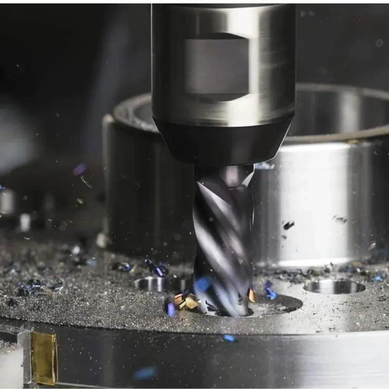
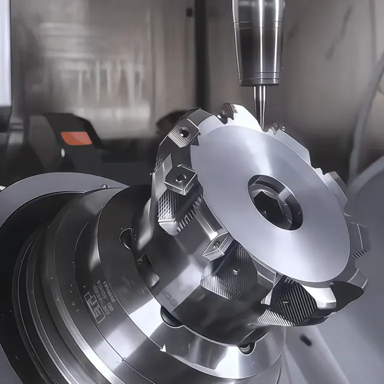
Five-axis CNC machining uses coordinated control of three linear axes and two rotary axes, allowing the cutting tool to approach workpiece surfaces from different directions and complete machining on multiple surfaces in a single setup or with fewer setups. For automotive parts with complex geometries, spatial hole positions, and precision features across multiple surfaces, five-axis machining can reduce repeated positioning, improve machining continuity, and provide flexible technical solutions for the custom manufacturing of complex components. TiRapid provides five-axis CNC machining and supporting manufacturing services for automotive component development, prototype production, and batch manufacturing. Through part structure analysis, machining process design, material selection, precision control, and quality inspection, design requirements for multi-surface automotive parts are converted into executable machining solutions, helping customers control manufacturing lead times, part quality, and production costs.
Machining Challenges and Five-Axis CNC Machining Solutions for Multi-Surface Automotive Parts
Multi-surface automotive parts typically require milling, drilling, boring, contour machining, and localized surface machining from different directions. The more complex the part structure, the closer the spatial relationships between machining surfaces, and the higher the requirements for workholding methods, tool paths, and machining accuracy.
Structural Characteristics and Machining Requirements of Multi-Surface Automotive Parts
Multi-surface automotive parts are not limited to components with multiple flat surfaces. They also include precision parts with inclined holes, complex curved surfaces, deep cavities, and irregular mounting structures. The dimensions and positions of different machining surfaces may be directly related. For example, a positional deviation in one mounting hole may affect the assembly and connection of adjacent components.
Common multi-surface automotive parts and their machining requirements are as follows:
| Automotive Part Type | Typical Structural Features | Five-Axis CNC Machining Applications |
| Engine and powertrain components | Multi-surface hole positions, mounting slots, curved surfaces, and complex contours | Multi-surface milling, inclined hole machining, and precision mounting surface machining |
| Transmission and drivetrain housings | Multi-directional connection holes, bearing bores, and internal cavities | Multi-surface machining, hole pattern machining, and housing contour machining |
| Automotive chassis connectors | Irregular shapes, inclined mounting surfaces, and spatial hole positions | Multi-angle milling, connection surface machining, and hole position machining |
| Steering system components | Curved structures, connection interfaces, and precision fitting positions | Curved surface machining, mounting surface machining, and precision contour machining |
| New energy vehicle structural parts | Lightweight structures, multi-surface interfaces, and complex spatial shapes | Multi-surface milling, structural contour machining, and connection position machining |
The machining priorities for these parts involve more than meeting the dimensional requirements of individual surfaces. They also require control over positional relationships between different machining surfaces, hole spacing, perpendicularity, and assembly interface dimensions. Five-axis CNC machining can reduce restrictions on tool access caused by complex structures by adjusting the relative position between the cutting tool and the workpiece.
Limitations of Traditional Multi-Setup Machining
Traditional three-axis CNC machining relies primarily on three linear motion axes to control tool movement. When automotive parts have multiple sides, inclined surfaces, or complex spatial features, machining usually requires fixture rotation, repositioning, or multiple machines.
Multiple setups can lead to the following problems:
- Repeated positioning may produce cumulative errors, making it difficult to maintain consistent positional relationships between different machining surfaces.
- Dedicated fixtures and positioning tooling increase preparation time, while complex parts may require the design of multiple workholding solutions.
- Deep cavities, inclined holes, and localized curved surfaces may be restricted by tool length and approach direction, increasing machining difficulty.
- Repeated workpiece removal, reinstallation, and transfer increase production steps and extend prototype delivery and batch production lead times.
For custom parts in the automotive development stage, frequent design modifications also increase the workload involved in fixture adjustments and machining program revisions. Five-axis CNC machining can reduce the need for certain dedicated fixtures and improve positioning consistency between different machining features through unified workholding datums.
Basic Five-Axis CNC Machining Solutions
Five-axis CNC machining uses the X, Y, and Z linear axes together with two rotary axes to control tool movement direction. The machine adjusts the tool orientation according to the part geometry, allowing the tool to approach different sides, inclined surfaces, and complex curved surfaces. For multi-surface automotive part machining, the process plan generally includes three-dimensional model analysis, machining datum determination, fixture design, tool path planning, and machining program verification. For parts suitable for consolidated machining, multiple surfaces can be completed in a single setup. For larger parts, complex structures, or components with special workholding requirements, accuracy is controlled by appropriately arranging the number of setups and machining sequence.Five-axis machining does not mean that every part must be manufactured on a five-axis machine. For automotive parts with simple structures and easily accessible machining surfaces, three-axis or four-axis machining may also meet manufacturing requirements. The appropriate combination of equipment and processes should be selected through part structure and machining cost analysis.

Process Design and Implementation Workflow for Five-Axis CNC Machining of Multi-Surface Automotive Parts
The machining quality of multi-surface automotive parts depends on equipment capabilities as well as the reasonableness of the preliminary process design. Corresponding machining solutions need to be developed according to different materials, part dimensions, structural shapes, and assembly requirements.
Part Drawing Analysis and Machining Datum Determination
Before machining begins, the part structure needs to be analyzed based on the customer’s three-dimensional models, two-dimensional engineering drawings, and technical requirements. This includes identifying critical dimensions, mating surfaces, hole positions, thin-walled areas, and machining features requiring particular control. For automotive transmission housings, particular attention should be paid to bearing mounting bores, connection surfaces, and positional relationships between different hole patterns. For chassis mounting brackets, the focus should be on mounting hole spacing, flatness of connection surfaces, and structural dimensions of load-bearing areas. The critical dimensions vary between parts, and machining datums must be determined according to actual assembly requirements. Reasonable machining datums provide a unified positioning reference for subsequent operations. By incorporating primary mounting surfaces, locating holes, or design datums into process planning, dimensional transfer errors between operations can be reduced. For parts with multiple precision machining surfaces, it is also necessary to evaluate whether datum conversion will affect hole positions, parallelism, perpendicularity, and contour accuracy.
Five-Axis Machining Path and Tool Orientation Planning
Five-axis CNC machining requires not only the determination of tool movement paths along the X, Y, and Z directions but also control over the movement orientations of the two rotary axes. Adjusting the tool direction can improve machining accessibility for complex curved surfaces, inclined surfaces, and localized deep cavities. During process design, appropriate tools, cutting directions, and machining sequences generally need to be selected according to the part geometry. Tool paths should avoid interference between fixtures, workpieces, and machine components while controlling tool overhang length to reduce vibration and deformation during cutting.
| Machining Feature | Key Process Design Considerations | Expected Machining Results |
| Multi-surface mounting holes | Establish a unified positioning datum and plan the hole machining sequence | Control hole spacing and relative positional relationships |
| Inclined holes and angled surfaces | Adjust tool angles and check tool access space | Reduce complex setups and auxiliary tooling |
| Curved surfaces and irregular contours | Optimize tool paths and cutting directions | Improve surface continuity and surface quality |
| Deep cavities and localized grooves | Select appropriate tool lengths and cutting parameters | Reduce the risk of interference, vibration, and tool wear |
For automotive parts with multiple machining surfaces, tool orientation planning needs to balance machining efficiency and dimensional stability. Reasonable path design can reduce air cutting and unnecessary rotary movements while helping minimize localized changes in cutting forces during machining.
Workholding Scheme and Machining Sequence Optimization
The workholding scheme directly affects part stability during machining. Multi-surface automotive parts may feature thin walls, cantilever structures, deep cavities, or irregular shapes. If clamping positions are selected improperly, cutting forces and clamping forces may cause localized deformation. Process engineers need to select positioning points and clamping locations based on the part structure to ensure that the workpiece remains stable during machining. For thin-walled aluminum alloy parts, clamping forces should be properly controlled. Methods such as staged material removal and reserving finishing allowances can reduce the risk of deformation. For parts with complex curved surfaces, the spatial relationship between the fixture and rotary table must also be checked. Although five-axis machines can reduce the number of workpiece rotations, not all machining features can be completed in a single setup. Repositioning or auxiliary machining operations may still be required for bottom surfaces, special internal cavities, or areas obstructed by fixtures. Material Selection, Precision Control, and Quality Inspection for Multi-Surface Automotive Parts. The material and operating environment of automotive parts directly affect the machining process. Different materials vary in cutting resistance, thermal conductivity, strength, weight, and surface treatment requirements. Material properties need to be considered alongside the actual application of the part to establish appropriate manufacturing and inspection plans.
Common Materials and Applications for Five-Axis CNC Machining of Automotive Parts
Common materials for multi-surface automotive parts include aluminum alloys, stainless steel, alloy steel, and engineering plastics. Material selection should be determined according to the part’s load-bearing requirements, operating environment, weight limitations, corrosion resistance requirements, and budget.
| Material Category | Common Materials | Applicable Parts and Machining Characteristics |
| Aluminum alloys | 6061, 7075, etc. | Suitable for lightweight brackets, housings, mounting components, and complex structural parts, with good machinability |
| Stainless steel | 304, 316, etc. | Suitable for connectors, mounting components, and certain automotive functional parts requiring corrosion resistance |
| Alloy steel | Selected according to part requirements | Suitable for connection structures and mechanical parts requiring high strength and wear resistance |
| Engineering plastics | POM, PEEK, ABS, etc. | Suitable for insulating components, non-metallic structural parts, test prototypes, and certain light-load parts |
Aluminum alloys are characterized by relatively low weight and high machining efficiency, making them suitable for many automotive structural parts and development prototypes. 7075 aluminum alloy offers relatively high strength, but its material cost, machining deformation, and subsequent processing requirements need to be evaluated comprehensively. 6061 aluminum alloy offers good applicability in terms of machinability, strength, and cost and can be used for various automotive components. Stainless steel and alloy steel generally require process development based on cutting parameters, tool materials, and cooling conditions. Engineering plastics require particular attention to clamping force, machining temperature, and localized deformation during cutting to avoid dimensional changes or surface defects.
Critical Dimension and Multi-Surface Machining Accuracy Control
The accuracy requirements for multi-surface automotive parts are generally concentrated on mounting holes, mating surfaces, positioning structures, and positional relationships between different machining features. Even if the dimensions of individual machining surfaces meet drawing requirements, deviations in the distances between hole positions or the perpendicularity between machining surfaces may affect final assembly. Five-axis machining can reduce errors caused by datum conversion by eliminating some repeated setups. However, final accuracy is still affected by factors such as machine condition, tool wear, material deformation, cutting parameters, and measurement methods.
Precision control can be achieved through the following process measures:
- Establish clear machining datums for critical mounting surfaces and locating holes to reduce unnecessary datum conversions.
- Separate rough machining from finishing operations, reserving an appropriate finishing allowance to reduce dimensional changes caused by the release of internal material stresses.
- Establish separate machining and inspection requirements for critical hole positions, mating surfaces, and thin-walled areas.
- Select appropriate measuring equipment according to part dimensions and tolerance requirements to verify whether machining results comply with engineering drawings.
For automotive parts with strict assembly requirements, it is recommended to clearly specify critical dimensions, tolerances, datum symbols, and surface roughness requirements in the drawings. Unified design, machining, and inspection standards can reduce rework caused by unclear technical requirements during manufacturing.
Surface Treatment and Quality Inspection of Multi-Surface Automotive Parts
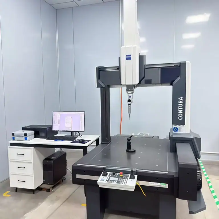
Surface treatment should be determined according to the part material and operating environment. Aluminum alloy parts can undergo anodizing, sandblasting, or other suitable surface treatment processes as required. Stainless steel parts can be cleaned, passivated, or surface-finished using appropriate methods based on their intended applications. Different treatment processes may affect the final dimensions, surface condition, and corrosion resistance of parts, so the relevant requirements should be confirmed before machining. Quality inspection should be carried out according to engineering drawings and customer acceptance standards. Routine inspections may include appearance, critical dimensions, hole positions, threads, machining burrs, and surface condition. For parts with complex spatial structures, coordinate measuring machines can be used for dimensional and geometric feature inspection as required.
For development prototypes and small-batch parts, dimensional inspection records, material certificates, and relevant quality documentation can be provided according to project requirements. For subsequent batch manufacturing, machining programs, material batches, critical process parameters, and inspection requirements must also remain consistent so that parts from different batches can be accepted according to unified standards. It should be noted that the capabilities of five-axis CNC machining equipment do not mean that every part can achieve the same tolerances. The achievable accuracy must be evaluated according to the material, structure, machining dimensions, inspection conditions, and drawing requirements.
Custom Manufacturing and Delivery Solutions for Five-Axis CNC Machining of Multi-Surface Automotive Parts
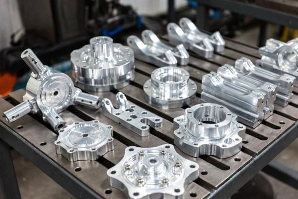
Automotive component projects typically progress through design verification, prototype production, small-batch production, and batch manufacturing. Different stages involve varying part quantities, dimensional requirements, and delivery schedules. Manufacturing solutions need to provide a certain degree of flexibility to accommodate development modifications and subsequent production requirements.
Service Workflow from Automotive Part Design Drawings to Finished Product Delivery
TiRapid can conduct part manufacturability assessments based on customer-provided three-dimensional models, two-dimensional drawings, and technical requirements, and develop machining solutions according to project needs. Five-axis CNC machining can be combined with conventional CNC milling, turning, sheet metal fabrication, and other manufacturing processes to provide customized manufacturing services for automotive parts with different structures.
| Manufacturing Stage | Main Service Content | Key Project Deliverables |
| Drawing evaluation | Analyze 3D models, materials, tolerances, assembly interfaces, and machining challenges | Clarify manufacturing requirements and process feasibility |
| Process design | Develop machining routes, workholding schemes, tool paths, and inspection requirements | Confirm machining methods and critical dimension control methods |
| Prototype production | Machine parts according to approved drawings, conduct dimensional inspections, and make necessary process adjustments | Verify structural, dimensional, and assembly requirements |
| Small-batch production | Manufacture parts according to confirmed processes and quality standards | Maintain consistency in part dimensions and machining quality |
| Batch manufacturing | Arrange manufacturing according to order quantities, production schedules, and inspection requirements | Balance delivery schedules, production stability, and cost control |
During the design evaluation stage, DFM (Design for Manufacturability) can help identify unreasonable machining structures, insufficient tool access space, excessively tight non-critical tolerances, and design features that may increase manufacturing costs. Communicating these issues before production can reduce temporary drawing modifications or rework during machining. For automotive parts in the development stage, customers can first verify assembly and structural designs through single-piece or small-batch prototypes, then adjust drawings and manufacturing requirements according to the verification results. Once subsequent production begins, confirmed process requirements can be reused to reduce repeated communication and process adjustments.
Manufacturing Arrangements for Single Prototypes, Small Batches, and Batch Production
Automotive part production quantities affect programming, tooling preparation, material procurement, and unit machining costs. Five-axis CNC machining offers considerable process flexibility and is suitable for complex structures and customized parts. However, the specific production plan still needs to be determined according to order volume and part characteristics. Single prototypes generally focus on design verification, dimensional confirmation, and assembly testing. At this stage, suitable machining materials and surface treatment methods can be selected according to actual requirements to avoid unnecessary investment in dedicated tooling before the design is finalized.
Small-batch production needs to balance delivery speed and part consistency. By standardizing machining datums, optimizing tool paths, and establishing fixed inspection standards, process variations during repeated production can be reduced. For automotive parts requiring repeated replenishment or continuous development, maintaining consistency in drawing revisions and technical requirements is also important. Batch manufacturing requires further evaluation of material supply, equipment scheduling, tool life, production cycle time, and quality inspection plans. For complex parts suitable for five-axis machining, production can be arranged in combination with other CNC machining processes to avoid using higher-cost machining methods for every part.
Machining Quotation, Delivery Lead Time, and Project Communication
Five-axis CNC machining quotations are generally related to material type, part dimensions, machining time, structural complexity, tolerance requirements, surface treatment, and order quantity. Parts with deep cavities, complex curved surfaces, thin-walled structures, or multiple precision hole patterns may require longer programming, machining, and inspection times.
To improve quotation and project evaluation efficiency, customers are advised to provide the following information:
- Three-dimensional models or two-dimensional engineering drawings, preferably in available formats such as STEP, IGES, and DWG.
- Material grades, part quantities, and expected production batches.
- Critical dimensions, tolerances, surface roughness, and surface treatment requirements.
- Delivery schedules, assembly requirements, and required inspection documentation.
TiRapid provides free DFM reports, instant quotations, and project support. Specific machining prices and delivery lead times are confirmed according to drawings, materials, quantities, and technical requirements. The services listed on the official website include five-axis CNC machining, custom automotive part manufacturing, and prototype and batch production support. Clarifying actual machining requirements before quotation can reduce repeated confirmation caused by incomplete information and help arrange material procurement, process preparation, and subsequent production schedules more efficiently.
Frequently Asked Questions
What Accuracy Can Five-Axis CNC Machining Achieve for Automotive Parts?
Machining accuracy needs to be determined according to the material, part structure, dimensions, tool conditions, and inspection methods. TiRapid’s CNC machining capabilities include tolerances as tight as ±0.01 mm, but this value cannot be directly applied to all automotive parts. Specific accuracy requirements should be evaluated according to engineering drawings and actual machining processes.
Is Five-Axis CNC Machining Suitable for Small-Batch Custom Automotive Parts?
It is suitable for customized parts featuring complex curved surfaces, multi-surface hole positions, inclined machining features, and precision mounting structures. For single prototypes and small-batch orders, it can reduce some dedicated fixture preparation and repeated setup work. However, parts with simple structures can also be machined using three-axis or four-axis equipment. The specific solution needs to be determined according to order quantity and machining difficulty.
What Documents Are Required for Automotive Part Machining?
Three-dimensional models, two-dimensional engineering drawings, material grades, part quantities, and tolerance requirements are generally required. If parts have special surface treatment, assembly, or inspection documentation requirements, these should also be provided during the quotation inquiry to facilitate accurate process evaluation and quotation.
Does Five-Axis CNC Machining Support Production from Prototypes to Batch Manufacturing?
Single prototypes, small-batch production, and batch manufacturing can be arranged according to project requirements. The prototype stage is primarily used to confirm design dimensions and assembly requirements. Subsequent production requires a specific plan based on order volume, material supply, machining processes, and quality standards. Actual delivery lead times and production quantities need to be determined through drawing evaluation and order confirmation.
The machining of multi-surface automotive parts requires consideration of structural complexity, machining accuracy, material properties, and production costs. Five-axis CNC machining can complete the machining of multiple surfaces, inclined hole positions, and complex curved surfaces by adjusting tool orientation, reducing some repeated setup operations and providing more flexible manufacturing methods for automotive part development and production. For customers requiring customized automotive connectors, engine peripheral components, transmission housings, chassis brackets, or new energy vehicle structural parts, providing complete drawings, material specifications, and tolerance requirements helps quickly determine process feasibility and develop a clear manufacturing solution. Whether the project is in product development, prototype verification, or batch production, confirming machining requirements in advance can help ensure smoother manufacturing and delivery.
Email: projects@tirapid.com
Phone: +86 760 8999 8536