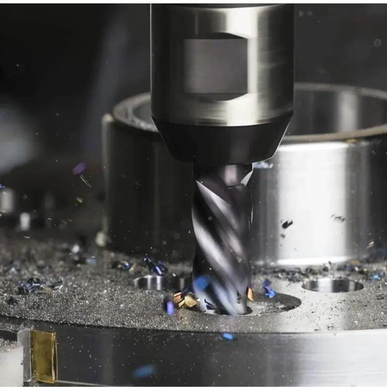
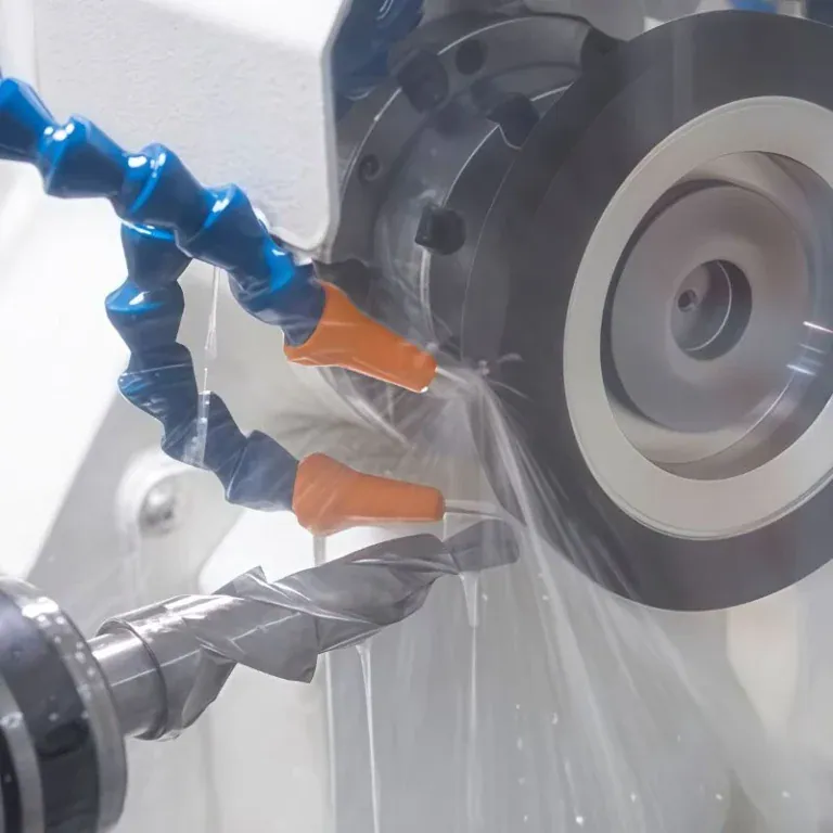
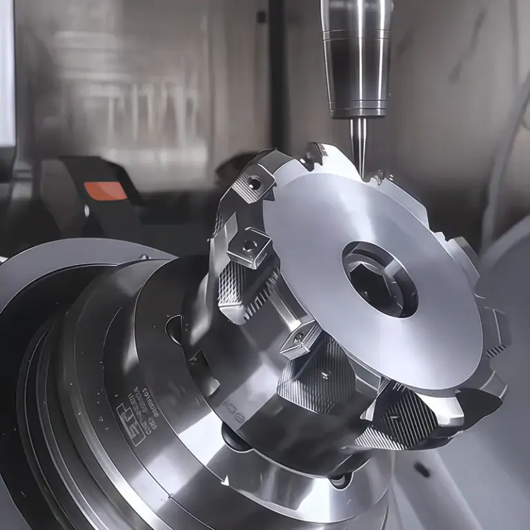
Medical automation equipment covers testing, sampling, conveying, positioning, sorting, and assembly processes. Its operation relies on many non-standard parts with precise dimensions and stable fits. The machining quality of mounting plates, support bases, positioning blocks, guide components, and shaft parts can directly affect mechanism movement and subsequent assembly. CNC machining is suitable for manufacturing parts with multiple varieties, small batches, and frequently changing structures. It can also support prototype development and subsequent production, providing flexible machining support for equipment development.
Which Parts of Medical Automation Equipment Are Suitable for CNC Machining?
Medical automation equipment has complex structures, and different parts perform different functions. Before machining, the structure, material, and accuracy requirements should be determined according to the actual application.
Equipment Structural and Mounting Parts
Mounting parts are mainly used to secure different modules, with machining focused on reference surfaces, hole positions, and assembly relationships.
- Mounting Base Plates: Machine mounting holes, positioning holes, counterbores, and reference surfaces to provide fixed positions for multiple functional modules.
- Support Bases and Connecting Plates: Machine steps, slots, and multi-directional holes according to the equipment layout.
- Mounting Frames: Reserve installation areas for sensors, wiring, and actuating components according to the internal mechanism layout.
Maintaining proper dimensional relationships in these parts can reduce adjustment work during equipment assembly.
Positioning, Transmission, and Actuation Components
Repeated movements within the equipment are sensitive to fit dimensions, so positioning and transmission components need machining accuracy based on their actual movement requirements.
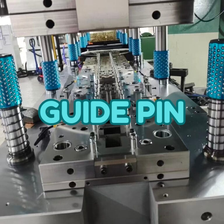
- Positioning Blocks and Guide Components: Control clearance according to the movement direction to ensure stable repeat positioning.
- Shafts and Mounting Bases: Focus on controlling hole diameter, shaft diameter, concentricity, and connection dimensions.
- Fixtures and Tooling: Machine positioning slots, clamping structures, and clearance areas according to product geometry.
Tolerances for functional components should be determined according to actual movement and assembly requirements to avoid unnecessary high-precision machining costs.
How Can CNC Machining Accuracy Be Controlled for Medical Automation Equipment Parts?
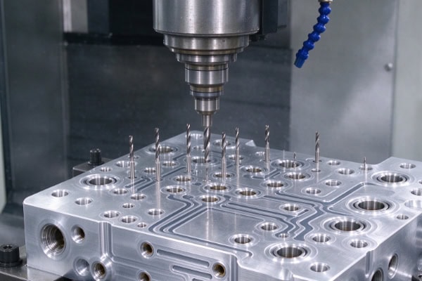
Medical automation equipment contains multiple interacting mechanisms. A single part meeting its dimensional requirements does not necessarily guarantee smooth operation of the complete mechanism. Therefore, machining should focus on datums, critical dimensions, and part deformation.
Conduct Drawing and Process Reviews Before Machining
Before formal production, the part structure should be reviewed based on 3D models, 2D drawings, and assembly relationships to identify potential machining issues in advance.
- Check Deep Slots and Deep Holes: Confirm that cutting tools can properly reach the machining areas.
- Define Machining Datums: Determine the main mounting surfaces, positioning surfaces, and critical hole positions.
- Plan the Fixturing Method: Reduce cumulative errors caused by repeated positioning.
Addressing manufacturing challenges in advance can reduce temporary process changes during machining.
Arrange Inspection According to Tolerance Requirements
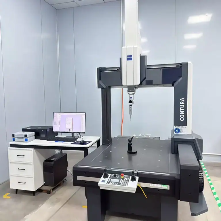
Different parts require corresponding inspection methods, and a single measuring tool cannot cover every dimension. Calipers and micrometers are suitable for certain conventional linear dimensions, while height gauges, vision measuring systems, or coordinate measuring machines can be selected for position, surface, and complex geometric features according to tolerance requirements. Matching inspection methods with drawing specifications allows the actual assembly requirements of the parts to be properly verified.
Control Machining Deformation of Metals and Engineering Plastics
Large mounting plates, thin-wall parts, and engineering plastics such as POM and PEEK may experience stress release and dimensional changes when substantial material is removed.
- Leave Sufficient Stock During Rough Machining: Avoid removing excessive material in a single operation.
- Separate Rough and Finish Machining Properly: Complete critical dimensions when the part is in a relatively stable condition.
- Control Clamping Force for Plastic Parts: Prevent localized deformation caused by excessive clamping pressure.
- Arrange Stress Relief When Necessary: For high-precision plastic parts, appropriate resting or stabilization processes can be arranged according to the material and structure.
Adjusting machining methods according to material characteristics helps improve dimensional stability after machining.
How Should Material, Surface Treatment, and Cleanliness Requirements Be Coordinated?
Not all parts of medical automation equipment operate in the same environment. Material selection and post-processing should be determined according to part function, contact media, cleaning methods, and equipment operating conditions.
Material Selection Should Match Part Function
Different materials have their own characteristics in terms of weight, strength, friction, corrosion resistance, and dimensional stability.
| Part Type | Common Materials | Machining Focus | Main Requirements |
| Mounting Plate | Aluminum Alloy | Flatness, Hole Positions | Lightweight Design, Assembly |
| Support Base | Aluminum Alloy, Stainless Steel | Reference Surfaces, Connection Holes | Strength, Stability |
| Shaft Components | Stainless Steel, Alloy Steel | Concentricity, Surface Quality | Motion Accuracy, Durability |
| Guide Components | POM, PEEK and Other Engineering Plastics | Fit Clearance, Deformation | Low Friction, Dimensional Stability |
| Precision Fixtures | Aluminum Alloy, Stainless Steel, Engineering Plastics | Positioning Dimensions, Surface Quality | Repeat Positioning, Cleanliness |
PEEK is suitable for certain structural parts requiring high chemical resistance, temperature resistance, or dimensional stability, while POM is suitable for certain low-friction, lightweight, and electrically insulating components. The specific material should still be selected according to the actual operating conditions.
Surface Treatment Should Match the Operating Environment
Surface treatment should not be selected solely based on material. Wear resistance, corrosion resistance, cleaning methods, and dimensional fit should also be considered.
- Aluminum Alloy Parts: Anodizing or hard anodizing can be considered according to wear and corrosion resistance requirements. Precision-fit areas need to account for dimensional changes caused by the treatment layer.
- Stainless Steel Parts: For components requiring higher corrosion resistance and surface cleanliness, passivation or electropolishing can be selected according to actual requirements.
- Precision-Fit Areas: Appropriate machining allowance should be reserved before surface treatment, and the required post-treatment dimensions should be determined in advance.
Surface treatment should be planned together with the actual function of the part to avoid reactive adjustments after machining.
Cleaning and Deburring Should Be Included in the Delivery Process
For parts that may contact reagents or samples or operate in clean environments, the cleanliness of the parts after machining also requires attention.
- Remove Machining Burrs: Focus on holes, slots, threads, and sharp edges to prevent residual debris from affecting mechanism operation.
- Remove Machining Residues: Remove cutting fluids, oil, and metal particles according to project requirements.
- Use Appropriate Clean Packaging: After cleaning, parts should be packaged appropriately to reduce the risk of recontamination during transportation.
Clarifying cleaning, deburring, and packaging requirements in advance allows parts to enter subsequent assembly processes more smoothly.
What Capabilities Should a CNC Supplier for Medical Automation Equipment Have?
Medical automation equipment parts often involve rapidly changing structures, variable order quantities, and clearly defined delivery requirements. Suppliers therefore need both machining capabilities and strong project coordination capabilities.
Ability to Handle Complex Non-Standard Structures
Automation equipment parts may contain holes, slots, steps, curved surfaces, and multi-directional machining features at the same time. A suitable process should be developed according to the part structure.
- Multi-Axis Machining: Suitable for multi-surface structures and complex angled features.
- Precision Milling and Turning: Covers different machining requirements for plate parts, structural components, and shaft parts.
- Proper Fixturing: Reduces the impact of repeated positioning on critical dimensions.
Combining equipment capabilities with process planning can improve the machining stability of complex non-standard parts.
Ability to Support R&D Modifications and Subsequent Production
Medical automation equipment may undergo changes to hole positions, dimensions, fixture structures, or module interfaces during development. The machining supplier therefore needs to quickly understand drawing changes and adjust the machining process accordingly. During small-batch or repeat production, consistency in materials, programs, inspection requirements, and critical dimensions also needs to be maintained.For parts with special cleanliness requirements, deburring, cleaning, and packaging specifications should also be defined in advance so that machining, post-processing, and delivery form a consistent workflow.
Manufacturing parts for medical automation equipment requires extending the considerations from design drawings to actual assembly and operating conditions. A suitable machining plan should address material characteristics, dimensional control, deformation risks, surface treatment, and cleanliness requirements in advance. Incorporating these factors into early process planning can reduce repeated modifications during development and help maintain more stable part fit after the components enter equipment assembly.