
Shaft machining is the precision manufacturing of cylindrical components that transmit torque, support rotating elements, or provide controlled motion within mechanical systems. Although a shaft may appear simple, its performance often depends on the relationship between several critical features, including diameters, bearing seats, shoulders, threads, keyways, runout, straightness, and surface finish. CNC turning normally creates the main geometry, while milling, drilling, grinding, and finishing complete functional and high-precision areas.
This guide explains how shaft machining works, the main CNC processes involved, common shaft types and materials, and the tolerances that matter most in real assemblies. It also covers long-shaft machining challenges, heat treatment, surface finishing, inspection, applications, cost factors, and practical design decisions for producing accurate and reliable shafts.
What Is Shaft Machining?
Shaft machining transforms bar stock, forgings, or other blanks into cylindrical mechanical components with controlled geometry and functional features. Because most shaft geometry is rotational, CNC turning is usually the core process, while other machining methods are added where the design requires slots, keyways, holes, threads, or tighter final dimensions.
The important distinction is that a finished shaft is not simply a round part. Its dimensions and features must work together around a common rotational axis so that bearings, gears, seals, couplings, and other components operate as intended.
What Does A Mechanical Shaft Do?
A mechanical shaft typically transfers rotational motion and torque from one component to another. Motor shafts, transmission shafts, pump shafts, and gearbox shafts all perform this basic function in different ways. Shafts may also support gears, bearings, pulleys, impellers, rollers, or other rotating components while carrying bending and cyclic loads.
This combination of rotation and load makes shaft geometry important. A diameter determines more than overall size: it can affect stiffness, bearing fit, torque capacity, and how the shaft responds to bending. Shoulders locate components axially, while keyways, splines, or other features transfer torque between the shaft and attached parts.
As rotational speed and load increase, small geometric errors become more important. Misalignment that seems minor on a stationary part can produce vibration, uneven wear, or noise once the shaft begins rotating.
Why Precision Matters In Shaft Machining
A shaft can meet its nominal diameter and still fail in service. Runout, coaxial alignment, straightness, and surface condition can be just as important as basic size because they determine how the shaft rotates and how mating components contact its surfaces.
An oversized bearing seat can create excessive interference and assembly stress, while an undersized seat may allow movement between the shaft and bearing. Similar problems can occur when different stepped diameters do not remain aligned around the same axis.
Surface finish also matters at bearing and seal locations. A rough surface can increase friction or accelerate wear, while an unsuitable seal surface can damage the sealing element and shorten service life. Shaft precision therefore needs to be treated as a combination of size, geometry, alignment, and surface condition, rather than as one tolerance value.
Common Types Of Machined Shafts
Shafts can be classified in many ways, but from a machining perspective, their geometry is often more useful than their name. A simple straight shaft and a multi-diameter splined shaft may perform similar rotational functions, yet their manufacturing requirements can be very different.
Understanding the main geometric forms helps determine which operations are likely to be required.
Straight And Stepped Shafts
A straight shaft maintains a largely constant diameter along its working length. It is relatively simple to turn and may be suitable for rollers, guides, supports, and uncomplicated drive systems.
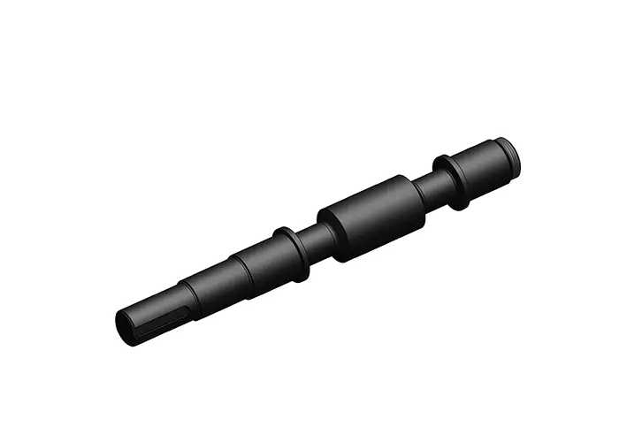
Stepped shafts contain multiple diameters separated by shoulders. These steps provide defined locations for bearings, gears, seals, spacers, and couplings. Because several diameters may need to share the same rotational axis, stepped shafts place greater emphasis on runout and alignment between features.
CNC turning is particularly effective for stepped shafts because multiple concentric diameters, shoulders, grooves, and end features can often be machined while maintaining a consistent rotational reference.
Keyed And Splined Shafts
Keyed and splined shafts are commonly used when torque must be transferred between a shaft and a mounted component.
A keyway provides a relatively simple mechanical connection between the shaft and a gear, pulley, or coupling. Splines distribute torque across multiple teeth and are often used where higher torque capacity, repeated assembly, or controlled angular positioning is required.
These features add machining complexity because their position must remain correctly related to the shaft axis. They can also introduce local stress concentrations, so the shaft’s geometry and loading should be considered together rather than treating the feature as an isolated slot.
Hollow, Tapered And Threaded Shafts
Hollow shafts reduce mass and can offer an efficient stiffness-to-weight relationship in applications where a solid cross-section is unnecessary. Their manufacturing difficulty depends on bore depth, wall thickness, straightness, and whether the internal and external diameters need to remain closely aligned.
Tapered shafts are useful where self-centering or controlled mating contact is required. The taper angle and surface condition must be appropriate for the mating component because even a small mismatch can affect alignment or contact.
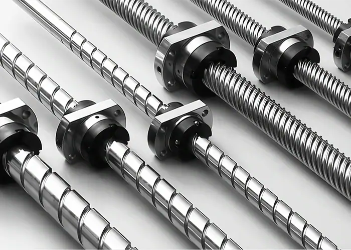
Threads are commonly added to shaft ends or intermediate sections for axial retention, adjustment, or assembly. These features are typically produced during turning or through a separate threading operation, depending on size and specification.
How Does The Shaft Machining Process Work?
There is no single production sequence for every shaft. A simple unhardened shaft may move directly from turning to inspection, while a precision shaft with bearing seats, heat treatment, and tight geometric requirements may need several roughing and finishing stages.
A typical manufacturing route follows the logic of material preparation → rough machining → feature machining → heat treatment when required → finish machining or grinding → finishing → inspection.
Raw Material And Rough Machining
Shaft production often begins with round bar stock, but forgings or other near-net-shape blanks can also be used for larger or more highly loaded components.
The initial machining stage removes excess material and establishes the basic cylindrical form. At this point, the goal is usually not to achieve final precision. Enough material may be left on critical surfaces to accommodate later finishing, heat-treatment distortion, or grinding.
Material condition also matters at this stage. Straightness, residual stress, hardness, and stock quality can influence how the shaft behaves as material is removed.
CNC Turning And Feature Machining
CNC turning produces most of the shaft’s rotational geometry, including external diameters, steps, shoulders, grooves, tapers, and many thread forms. The workpiece rotates around its axis while the cutting tool controls the diameter and axial profile.
Features that are not rotational are usually produced with complementary operations. Milling can create keyways, flats, slots, or selected spline forms, while drilling adds axial or cross holes.
Modern multi-axis and turn-mill equipment can sometimes complete several of these operations in one setup. Reducing unnecessary repositioning can be valuable when multiple features need to remain accurately related to the shaft centerline.
Grinding And Final Inspection
Turning can produce accurate shaft geometry, but some bearing seats, sealing areas, or high-speed rotating surfaces require tighter dimensional control or a smoother finish than turning alone can consistently provide.
Cylindrical grinding removes a small amount of material to bring critical diameters closer to final size while improving roundness and surface quality. It can also be useful after heat treatment when distortion must be corrected.
Once machining is complete, inspection confirms that the shaft meets the drawing rather than simply looking correct. Diameter, runout, straightness, alignment between functional diameters, and surface roughness are among the characteristics that may need verification.
Main Shaft Machining Methods
Different machining processes solve different problems. Turning creates the basic rotational form, milling and drilling add local features, and grinding is typically reserved for dimensions or surfaces that require greater final control.
Using the right combination of processes is generally more effective than trying to force every feature into one operation.
CNC Turning
CNC turning is the foundation of most shaft machining because the process naturally matches cylindrical geometry. As the shaft rotates, the cutting tool can generate diameters, shoulders, grooves, tapers, and other concentric features efficiently.
One of turning’s biggest advantages is the ability to maintain related rotational features from a common setup. This is particularly useful for stepped shafts where several diameters must remain aligned.
Turning also offers good repeatability for production batches. Once the program, workholding, and tool strategy are established, the same geometry can be reproduced consistently without relying on repeated manual adjustment.
CNC Milling And Drilling
Milling and drilling complete the features that turning cannot create efficiently. Keyways, flats, slots, cross holes, mounting features, and selected contours are typical examples.
Their main engineering challenge is positional relationship. A keyway may be dimensionally correct but still cause assembly problems if its angular or axial position is incorrect relative to other features.
For shafts with several turned and milled features, minimizing unnecessary setups and maintaining reliable datums helps protect alignment throughout the manufacturing sequence.
Cylindrical And Centerless Grinding
Grinding is generally a finishing process rather than the main method for creating shaft geometry. It is used when a critical diameter needs better roundness, dimensional accuracy, or surface finish than the previous turning operation can reliably provide.
Cylindrical grinding is well suited to shafts where the relationship between several features must be tightly controlled. It is also useful for stepped or more complex shafts because specific diameters can be targeted.
Centerless grinding is often better suited to relatively simple cylindrical components and higher production quantities because the process can support continuous or efficient repetitive grinding. The correct choice depends on geometry, accuracy, volume, and how individual surfaces relate to one another.
Shaft Machining Tolerances And Precision Requirements
Precision shafts are defined by more than a general ± dimensional tolerance. Bearing fits, runout, straightness, surface roughness, and the relationship between multiple diameters can all affect how the finished shaft behaves under rotation.
For this reason, the drawing should distinguish genuinely critical features from dimensions that do not need the same level of control.
Diameter Tolerance And Bearing Fits
Bearing seats are among the most tolerance-sensitive features on many shafts. Their size determines whether the bearing assembles correctly and whether the intended relationship between the inner ring and shaft is maintained.
ISO shaft tolerance classes such as h6 or g6 may appear on engineering drawings, but the correct fit depends on the bearing arrangement, load direction, rotation, temperature, assembly method, and recommendations from the bearing supplier. A single tolerance class should not be applied universally to every shaft.
The key principle is functional control. A shaft diameter should be tight enough to provide the required fit, but specifying unnecessarily tight tolerances on unrelated regions only increases machining and inspection cost.
Runout, Concentricity And Straightness
Runout measures how much a surface varies as the shaft rotates relative to a datum axis. It is particularly useful for bearing seats, seal locations, and other rotating surfaces where actual rotational behavior matters.
Concentricity is often used informally in machining discussions to describe whether multiple diameters share a common centerline. On controlled drawings, designers may instead use appropriate GD&T controls such as runout or position depending on the functional requirement.
Straightness becomes increasingly important as shaft length increases. A shaft may have accurate individual diameters but still perform poorly if the overall axis bends enough to create vibration, uneven contact, or alignment problems.
These geometric requirements should therefore be selected according to how the shaft will rotate and assemble, rather than being added simply because the component is described as “precision.”
Surface Finish For Bearing And Seal Areas
Surface roughness affects friction, lubrication, wear, sealing behavior, and sometimes fatigue performance.
A bearing seat generally benefits from a controlled finish that supports stable contact and assembly without unnecessary roughness. Some published machining guidance cites approximately Ra 0.4–1.6µm for certain bearing surfaces, but the correct value should ultimately follow the bearing, seal, material, load, and application specification rather than being treated as a universal target.
Seal surfaces can have their own requirements because the wrong roughness or surface pattern may accelerate seal wear or leakage. When a surface has a clear tribological or sealing function, its finish should therefore be specified independently from ordinary non-contact areas.
Materials Used For Shaft Machining
Material selection has a direct effect on shaft strength, fatigue resistance, weight, corrosion behavior, machinability, heat treatment, and final cost. A material that machines easily is not necessarily the best choice for a highly loaded rotating part.
The most practical selection starts with load and environment, then considers manufacturing requirements.
| Material | Main Advantage | Typical Shaft Use |
| Carbon Steel | Cost and practical machinability | General mechanical shafts |
| Alloy Steel | Strength, fatigue and wear resistance | High-load drive shafts |
| Stainless Steel | Corrosion resistance | Food, medical and marine equipment |
| Aluminum | Low weight and good machinability | Lightweight rotating components |
| Titanium | High strength-to-weight ratio | Aerospace and high-performance parts |
| Nickel Alloy | Heat and corrosion resistance | Severe-temperature equipment |
Carbon steel, alloy steel, stainless steel, aluminum, titanium, nickel alloys, brass, and other engineering materials all appear in shaft manufacturing, with the correct choice depending on functional requirements.
Carbon And Alloy Steel Shafts
Carbon steels are widely used for general-purpose shafts because they offer a practical balance of strength, availability, machinability, and cost. Grades in the medium-carbon range, such as 1045, are common examples where moderate loads and wear resistance are required.
Alloy steels are typically considered when the shaft sees higher torque, cyclic loading, wear, or more demanding fatigue conditions. Materials such as 4140 or comparable chromium-molybdenum steels can also respond well to heat treatment.
The trade-off is manufacturing difficulty. Greater hardness and strength can increase cutting forces, tool wear, and finishing requirements, so material performance and manufacturing cost need to be considered together.
Stainless Steel Shafts
Stainless steel shafts are selected primarily when corrosion resistance is important. Food-processing equipment, marine systems, medical equipment, chemical environments, and exposed machinery are common examples.
The specific grade matters. Austenitic, martensitic, and precipitation-hardening stainless steels offer different combinations of corrosion resistance, strength, hardness, heat-treatment response, and machinability.
Compared with many carbon steels, some stainless grades are more prone to work hardening and can be less forgiving during machining. This can influence tooling, cycle time, and achievable surface finish.
Aluminum, Titanium And Specialty Alloy Shafts
Aluminum is attractive where reducing rotating mass is important and loads are moderate enough for its lower stiffness. Its good machinability also makes it practical for many lightweight prototypes, instruments, automation components, and selected high-speed systems.
Titanium provides a much higher strength-to-weight ratio and strong corrosion resistance, making it useful for aerospace and demanding performance applications. Those advantages come with more difficult machining and higher material cost.
Nickel-based alloys are used where heat and corrosion conditions exceed the capability of more conventional shaft materials. They can provide excellent service performance, but machining difficulty and tool wear usually make them a specialized rather than default choice.
Heat Treatment And Surface Finishing For Shafts
The properties of a shaft are determined not only by the base material. Heat treatment can change hardness and fatigue performance, while surface treatment can improve corrosion, wear, appearance, or friction behavior.
These secondary processes need to be planned together with final dimensions because some treatments can alter the shaft after initial machining.
Heat Treatment And Surface Hardening
Hardening and tempering may be used on steel shafts that need higher strength or wear resistance, while induction hardening can selectively harden functional surfaces without treating the entire cross-section in the same way. Stress-relief treatments may also be used where residual stress is a concern.
A major manufacturing consideration is distortion. Heat treatment can change straightness, roundness, or final diameter, which is why high-precision shafts are often rough-machined first and then finish-machined or ground after heat treatment.
This sequence allows the material properties to be established before the most critical final surfaces are brought to size.
Common Shaft Surface Finishes
Surface treatment depends strongly on the shaft material and operating environment. Stainless steel shafts may be passivated where improved surface cleanliness and corrosion behavior are required, while aluminum components can be anodized for corrosion and surface protection.
Plating can be used on selected steel or other metal shafts when wear, corrosion resistance, or a particular surface property is needed. Polishing and grinding, meanwhile, are primarily mechanical finishing methods used to improve smoothness and dimensional control.
The finish should always be matched to the functional surface. A decorative treatment on a non-contact area and a precision bearing or seal surface may require completely different specifications.
Challenges In Precision Shaft Machining
Shaft machining becomes more difficult as length increases, materials become harder, or multiple precision features must remain aligned. These challenges are less about producing a cylindrical shape and more about maintaining stability throughout the complete machining sequence.
Understanding where errors develop makes it easier to assign tolerances realistically and plan the correct finishing operations.
Long Shaft Deflection And Vibration
Long, slender shafts behave less like rigid bars and more like flexible beams under cutting forces. As the length-to-diameter ratio increases, deflection, vibration, and dimensional instability become increasingly important.
Deflection can produce diameter variation or taper because the workpiece moves away from the cutting tool. Vibration can leave chatter marks, reduce surface quality, and make dimensional control less predictable.
Tailstocks, steady rests, controlled cutting forces, and staged roughing and finishing can improve stability. The objective is to prevent the shaft from bending during machining rather than relying on final inspection to discover the error afterward.
Maintaining Alignment Across Multiple Features
A complex shaft may contain several diameters, threads, shoulders, holes, and keyways produced in different operations. Each new setup creates another opportunity for alignment error.
Whenever possible, machining related rotating features from a common reference can reduce tolerance accumulation. When the part must be repositioned, consistent datums and controlled fixturing help preserve the relationship between earlier and later features.
This is particularly important for stepped shafts and high-speed components. Individual dimensions may all pass inspection while the complete shaft still develops excessive runout if their axes do not relate correctly.
Machining Hardened And Difficult Materials
Hard alloy steels, stainless steels, titanium, and nickel alloys place greater demands on tools and process stability than easily machined mild steel or aluminum.
Higher cutting forces and tool wear can influence diameter consistency and surface finish over a production batch. Some materials also generate or retain more heat during cutting, which can contribute to thermal movement or tool degradation.
The most appropriate shaft material is therefore not simply the strongest available option. It should deliver the required service performance without adding manufacturing difficulty that provides no functional benefit.
Shaft Machining Quality Inspection
Inspection closes the loop between the engineering drawing and the actual rotating component. Because shaft performance depends on several related dimensions and surfaces, checking only one outside diameter is rarely enough for precision applications.
The inspection plan should focus on characteristics that directly affect fit, rotation, sealing, and load transfer.
Dimensional And Geometric Inspection
Micrometers are commonly used to verify shaft diameters and bearing seats because they provide direct, high-resolution size measurement.
Runout can be checked by rotating the shaft against an indicator or with more specialized measurement equipment. Straightness, axial relationships, and more complex geometry may require dedicated fixtures, roundness equipment, or CMM inspection depending on the drawing requirements. Precision grinding and controlled inspection are commonly used together when tight shaft tolerances are required.
The measurement method should reflect the specification. A feature controlled for runout, for example, should be inspected in a way that evaluates rotational variation rather than only checking its diameter.
Surface And Material Verification
Surface roughness measurement becomes important on bearing, seal, or sliding areas where the texture affects actual operation.
When shafts are heat treated, hardness testing may also be required to confirm that the specified material condition has been achieved. Material certificates or other verification can be important when alloy identity and traceability are part of the project requirements.
Together, dimensional, geometric, surface, and material checks provide a much more meaningful indication of shaft quality than basic dimensional inspection alone.
Applications Of Machined Shafts
Machined shafts are used wherever controlled rotation, torque transmission, or linear guidance is required. The basic geometry may be similar across industries, but the priorities can change substantially depending on speed, load, corrosion, cleanliness, and reliability requirements.
A successful shaft therefore needs to be designed for its actual operating environment rather than for an industry label alone.
Automotive
Automotive shafts include drive, transmission, motor, and other rotating power components. These applications frequently place strong emphasis on torque capacity, fatigue resistance, wear, balance, and long-term dimensional stability.
A rotating drivetrain shaft experiences cyclic loads rather than a single static load, making material selection and stress concentration particularly important.
Electric-drive systems can also place demanding requirements on motor shafts, where runout and balance influence high-speed rotational behavior.
Industrial Equipment
Pumps, gearboxes, electric motors, conveyors, compressors, rollers, and process equipment all rely on machined shafts.
Bearing fits and alignment are particularly important because these machines may operate continuously for long periods. An error that appears small during assembly can become continuous vibration, wear, noise, or seal failure during thousands of operating hours.
Industrial shaft design therefore often prioritizes durability and maintainability alongside basic dimensional accuracy.
Medical
Medical equipment may use precision shafts in motion-control systems, pumps, instruments, laboratory equipment, and other mechanical assemblies.
Material requirements can emphasize corrosion resistance and cleanability, while dimensional requirements depend on the motion and assembly involved.
Not every stainless steel or precision shaft is automatically suitable for medical use. Specific materials, surface conditions, regulatory requirements, and cleaning or sterilization environments need to be evaluated for the particular product.
Aerospace And Automation
Aerospace applications often prioritize fatigue performance, weight reduction, reliability, and material traceability. Titanium, alloy steel, stainless steel, or other specialized materials may be selected depending on load and environment.
Automation and robotics can involve motor shafts, linear shafts, rollers, actuator components, and other motion parts. Here, straightness, runout, alignment, and repeatability can directly influence positioning accuracy and smooth motion.
Both sectors demonstrate why shaft performance depends on more than nominal dimensions: the component has to remain accurate while moving under real loads.
What Affects Shaft Machining Cost?
Shaft machining cost depends on the complete manufacturing requirement rather than simply the shaft’s length and diameter. Material, geometry, tolerances, heat treatment, grinding, inspection, and production volume can all change the amount of work required.
The most economical shaft drawing is therefore not the one with the fewest dimensions, but the one that clearly distinguishes critical features from ordinary geometry.
Material And Shaft Size
Material affects both raw stock price and machining time. A relatively machinable carbon steel shaft may require less tool and machine time than a hardened alloy or nickel-based material of the same shape.
Diameter and length also matter. Larger shafts use more stock and require more material removal, while long slender components may need additional support, reduced cutting forces, and more attention to straightness.
These factors become particularly important when a simple-looking shaft is large enough or flexible enough to require specialized workholding.
Tolerance And Surface Finish
Tighter tolerances generally require more controlled finishing and more inspection. When turning alone cannot reliably satisfy the requirement, cylindrical grinding may add another manufacturing stage.
The same applies to surface finish. A general turned surface and a precision bearing seat should not automatically receive the same requirement.
Restricting very tight tolerances to bearing seats, seals, mating diameters, or other functional features can reduce unnecessary manufacturing cost without sacrificing product performance.
Geometry And Production Volume
A basic straight shaft is relatively efficient to machine. Keyways, splines, cross holes, multiple threads, deep grooves, and closely controlled steps add operations and setup time.
Production volume changes the economics as well. Programming, tooling, workholding, and setup effort represent a larger portion of the price for one prototype than for a repeat batch.
For production shafts, design stability and repeatability can allow the manufacturing process to be optimized over more parts, improving overall efficiency.
How To Design A Shaft For CNC Machining
Good shaft design begins with mechanical function, but manufacturability determines how efficiently that function can be achieved. A design does not need to be simplified until it stops working, it needs to avoid complexity that provides no useful performance.
Three areas deserve particular attention: material and diameter, stress concentration, and tolerance allocation.
Match Diameter And Material To The Load
Shaft diameter and material should be selected according to torque, bending, speed, fatigue, environment, and stiffness requirements.
Increasing strength through material selection can sometimes reduce required section size, but material properties should not be considered independently from stiffness or manufacturing behavior. For example, replacing steel with aluminum can reduce weight but also changes elastic stiffness significantly.
The correct design balances geometry and material rather than expecting one property to solve every requirement.
Avoid Unnecessary Stress Concentrations
Shoulders, grooves, threads, keyways, and cross holes all interrupt an otherwise continuous shaft section and can increase local stress.
Smooth transitions and appropriate fillets can reduce stress concentration around stepped diameters, especially on shafts exposed to cyclic bending or torsion. The exact radius still needs to remain compatible with mating components such as bearings or shoulders.
Keyways and other torque-transfer features should likewise be sized and positioned with both load and machinability in mind rather than simply added after the shaft diameter has been finalized.
Apply Tight Tolerances Only Where Needed
Precision costs money when it requires additional machining, grinding, controlled fixturing, or inspection. Not every surface on a shaft needs the same tolerance.
Critical bearing seats, seal surfaces, datums, and mating features may justify close control, while clearance regions and non-functional diameters can often accept broader limits.
This approach makes the drawing easier to manufacture and inspect while concentrating process capability where it directly affects shaft performance.
How To Choose The Right Shaft Machining Method
The most efficient machining strategy usually follows the functional hierarchy of the shaft. First create the rotational geometry, then add non-rotational features, and finally apply higher-precision finishing only where it provides measurable value.
In practical terms, the decision can often be summarized as turning for geometry, milling or drilling for features, and grinding for precision.
Use Turning For Main Shaft Geometry
CNC turning should normally handle the primary diameters, shoulders, tapers, grooves, and rotational features because it provides an efficient and stable way to generate concentric geometry.
For simple shafts with moderate tolerance and surface requirements, turning may produce the majority of the finished part without requiring grinding.
Add Milling Or Drilling For Functional Features
Milling or drilling becomes necessary when the shaft includes keyways, flats, cross holes, slots, or other geometry that does not follow the rotational profile.
These operations should be planned around the shaft’s datums and critical turned features so that their position remains consistent with the final assembly.
On appropriate equipment, combining turning and milling in fewer setups can improve workflow and reduce unnecessary repositioning.
Use Grinding For Critical Fits And Finishes
Grinding should be added where the functional requirement justifies it, not simply because the component is called a precision shaft.
Bearing seats, seal diameters, high-speed rotating areas, hardened surfaces, and parts that require improved roundness or straightness are common candidates.
This targeted approach avoids adding an expensive finishing stage to surfaces that already meet their requirements after turning while still providing the additional control needed on truly critical areas.
FAQs
Which Material Is Best For Shafts?
There is no single best shaft material. 1045 carbon steel is a practical choice for general-purpose shafts because it balances strength, machinability, and cost. 4140 alloy steel is better for higher loads, fatigue, and wear, while stainless steel is preferred for corrosion resistance. Aluminum or titanium may be selected when reducing weight is more important.
How To Machine A Keyway In A Shaft?
A shaft keyway is commonly machined by CNC milling using an end mill or keyseat cutter. The shaft is positioned from a controlled datum, and the slot is machined to the specified width, depth, and location. After machining, the keyway should be deburred and inspected because its fit and position directly affect torque transmission and assembly.
How To Machine Splines On A Shaft?
External shaft splines can be produced by hobbing, spline milling, shaping, or rolling, depending on the spline geometry, material, accuracy, and production volume. For hardened or high-precision splines, grinding may be added after heat treatment to improve tooth accuracy and surface finish. The selected process should match the required torque capacity and fit.
Conclusion
Reliable shaft machining depends on coordinating material, CNC turning, feature machining, grinding, tolerances, runout, straightness, and surface finish with the shaft’s actual operating conditions. A successful shaft is not simply one that matches its nominal diameter, its critical surfaces must remain correctly aligned and finished so bearings, seals, gears, and other mating components can operate smoothly under real rotational loads.
At TiRapid, we provide precision CNC machining and manufacturing services for custom shafts and other rotational components. Our capabilities support CNC turning, complex feature machining, material selection, dimensional inspection, and precision finishing requirements for prototypes and low-volume production.
















