Chamfer machining is the process of removing material from an edge, hole, or contour to create a controlled angled surface. In CNC manufacturing, chamfers are commonly used to remove sharp edges, improve assembly, provide clearance, protect vulnerable edges, prepare features for fasteners, and create specific functional transitions between surfaces.
This guide explains chamfer machining methods, tool selection, size and angle control, drawing callouts, material effects, common defects, inspection methods, and practical CNC design tips.
What Is a Chamfer in Machining?
A chamfer in machining is a straight angled surface created by cutting away the sharp edge between two adjoining surfaces. In CNC machining, a chamfer can be applied to external edges, holes, slots, pockets, shoulders, threaded entrances, and complex contours. Its purpose may be simple edge breaking, but it can also become a functional design feature when it controls assembly, clearance, fastener seating, or part handling.
A common chamfer specification is 1 × 45°, where the first value defines the chamfer size and the second defines the angle. However, chamfers are not limited to 45°. Depending on the part design, a chamfer may be defined by one distance and one angle, by two different distances, or by a custom geometry that supports a specific assembly or clearance requirement.
The key point is that a chamfer is not always the same as deburring. Deburring removes unwanted sharp material after machining, while a defined chamfer creates a controlled geometric feature. If the drawing simply says “break sharp edges,” the process may allow more flexibility. If the drawing specifies a dimension such as C0.5 or 1 × 45°, the manufacturer must machine and inspect that edge as a measurable feature.
Chamfer vs. Bevel
A chamfer and a bevel both describe angled geometry, but they are often used differently in engineering and manufacturing. A chamfer usually refers to a smaller angled edge treatment applied to the corner of a part, while a bevel may describe a larger angled surface, edge preparation, or sloped face. In many machining discussions, the terms may overlap, but drawings should not rely on wording alone.
For CNC production, the actual geometry is more important than the term. If the drawing defines a 1 × 45° edge, the machinist knows the required size and angle. If it only says “bevel edge” or “chamfer edge” without dimensions, different suppliers may interpret the requirement differently. Clear size, angle, location, and tolerance are therefore more important than the label itself.
Why Are Chamfers Important?
Chamfers are important because they help solve real manufacturing and assembly problems. They can remove sharp edges, make parts safer to handle, reduce burr-related issues, protect fragile corners, improve assembly guidance, and provide clearance for mating components. A well-designed chamfer can make a part easier to manufacture and easier to use.
For example, a shaft entering a bore may catch on a sharp edge if both features are perfectly square. A small chamfer on the shaft end or hole entrance creates a lead-in surface that helps the parts align during assembly. Similarly, a chamfer around a fastener hole can help a screw sit properly, while a light chamfer on a machined plate can reduce handling risk.
Chamfers also help control edge conditions before finishing. Sharp edges can chip, cut operators, accumulate burrs, or create inconsistent results during anodizing, plating, painting, or coating. A controlled chamfer creates a more predictable transition, but it should still be placed only where it supports the part function. Chamfering every edge without purpose can increase cost and remove useful material.
What Are the Main Types of Chamfers?
The main types of chamfers used in CNC machining include standard 45° chamfers, non-standard angle chamfers, asymmetric chamfers, hole chamfers, contour chamfers, and custom chamfers. Each type exists because different part features require different edge geometry. The correct choice depends on assembly function, available material, tool access, mating components, and whether the chamfer must be controlled as a precision feature.

A standard 45° chamfer is the most common because it is simple to define and efficient to machine. However, many parts require something more specific. A hole chamfer may support screw insertion, a two-distance chamfer may solve an asymmetric clearance problem, and a contour chamfer may follow a curved or multi-axis geometry.
| Chamfer Type | Main Characteristic | Typical Application |
| Standard 45° Chamfer | Equal angled edge | General edge breaking and assembly lead-in |
| Non-Standard Angle Chamfer | Specific angle requirement | Clearance, mating features, special geometry |
| Asymmetric Chamfer | Different distances on each side | Uneven space or directional assembly |
| Hole Chamfer | Angled hole entrance | Fasteners, shafts, pins, threads |
| Contour Chamfer | Follows curved or complex profile | Housings, molds, aerospace-style features |
| Custom Chamfer | Non-standard geometry | Functional or application-specific design |
Standard 45° Chamfer
A standard 45° chamfer is widely used because it balances simplicity, manufacturability, and function. It is easy to call out on drawings, easy to model in CAD, and usually compatible with common chamfer mills or countersink tools. For many general-purpose edges, a 45° chamfer provides enough edge relief without creating unnecessary manufacturing complexity.
However, engineers should not choose 45° only because it is common. If the chamfer must guide a mating component, match a fastener, create special clearance, or preserve material thickness, another angle may be more appropriate. The best chamfer angle is the one that supports the actual function of the part.
Non-Standard Angle Chamfer
A non-standard angle chamfer is used when the design needs a specific edge geometry that a 45° chamfer cannot provide. For example, a shallow angle may be used to create a smoother insertion path, while a steeper angle may provide clearance in a tight assembly. Fastener geometry, mating part contact, and tool accessibility can also influence the angle.
Non-standard angles can be useful, but they may increase manufacturing effort. A special angle may require a dedicated tool, additional CAM programming, or more careful inspection. Before specifying one, engineers should confirm that the non-standard angle provides a real functional benefit.
Asymmetric Chamfer
An asymmetric chamfer removes different amounts of material from the two adjoining surfaces. This type is useful when one side of the edge has limited space or when the chamfer must follow a directional assembly requirement. Instead of defining the feature only by one distance and one angle, the drawing may define two distances.
This is especially important when the chamfer interacts with another component. If the wrong surface receives too much material removal, the part may lose contact area, clearance, or alignment. For this reason, asymmetric chamfers should be clearly dimensioned on the engineering drawing.
Hole Chamfer and Countersink
A hole chamfer is used at the entrance of a drilled, reamed, bored, or milled hole. It may remove the sharp edge left after drilling, help a pin or shaft enter, guide a screw, or prepare a hole for threading. A countersink is a more specific type of hole feature designed to accommodate a fastener head or create a defined conical opening.
The difference matters because a simple hole edge break may have loose requirements, while a countersink can be a functional feature. If a flat-head screw must sit flush with the surface, the countersink angle and opening diameter must match the fastener. In that situation, the chamfer is not just cosmetic, it directly affects assembly.
Contour Chamfer
A contour chamfer follows a curved edge, angled wall, 3D profile, or complex part boundary. These features are common on housings, molded-part prototypes, aerospace components, automation parts, and other CNC-machined components with non-rectangular geometry. They are more challenging than straight chamfers because the tool must maintain a consistent edge condition while moving along changing geometry.
For simple flat edges, a standard 3-axis toolpath may be enough. For complex contours, the CAM strategy must consider tool orientation, collision avoidance, tool engagement, and surface continuity. If these factors are not controlled, the chamfer may vary visibly along the profile.
How Is Chamfering Done in CNC Machining?
CNC chamfering is done by moving a cutting tool along the required edge, hole, or contour to remove material at a controlled angle and depth. The process may use milling, turning, countersinking, deburring, grinding, or dedicated chamfering equipment depending on geometry, material, tolerance, and production needs. Precision chamfering requires control of tool geometry, toolpath, cutting parameters, workholding, tool wear, and inspection.
In CNC manufacturing, chamfering is often integrated into the main machining sequence rather than treated as a completely separate operation. A milled housing may receive chamfers after pocketing and profiling. A turned shaft may receive its chamfers during the same cycle as the main diameter. A drilled hole may be chamfered or countersunk immediately after drilling.
The correct approach depends on the required result. A general edge break can often be handled with a simple deburring operation, but a defined chamfer such as 1 × 45° must be machined to a controlled geometry. The tighter the tolerance or the more functional the chamfer, the more attention must be paid to the machining method.
CNC Milling
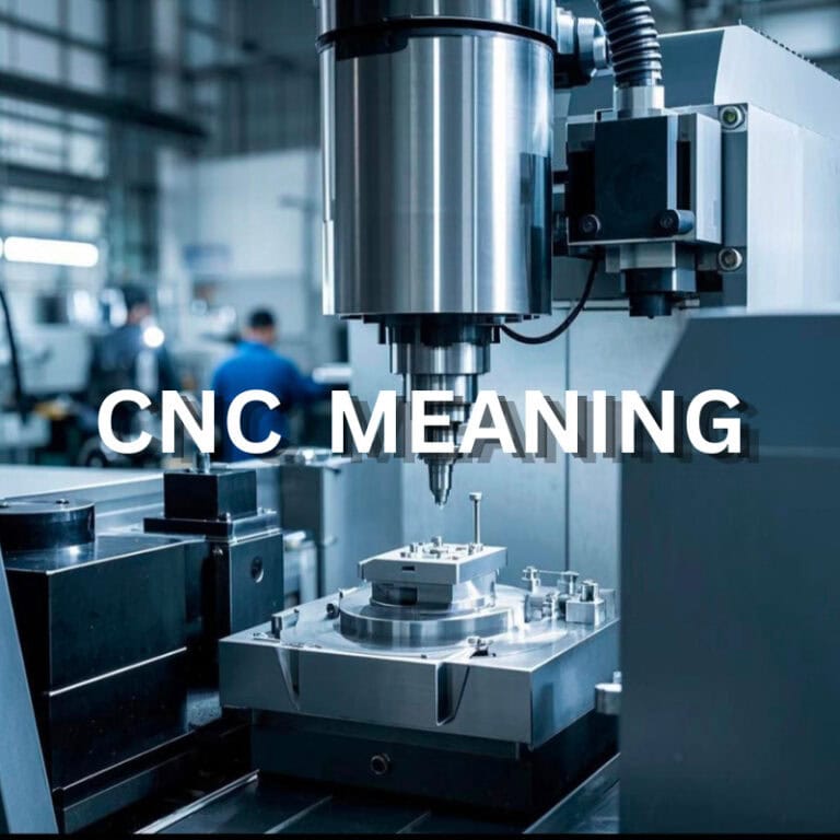
CNC milling is one of the most common methods for chamfer machining because it can accurately control chamfer location, width, depth, and angle on flat edges, pockets, slots, profiles, and other non-rotational features. A dedicated chamfer mill is usually the most direct option, while an end mill can also generate chamfers through a programmed toolpath when the geometry requires flexibility.
A chamfer mill creates the angled surface through its cutter geometry. The CNC program controls where the tool engages the edge and how much material is removed. For a consistent chamfer, the tool must follow the programmed path accurately, and the cutting system must remain stable.
Several factors influence the result:
- Tool runout
- Tool overhang
- Machine rigidity
- Workholding stability
- Cutting depth
- Feed rate and spindle speed
- Cutter wear
- Toolpath direction
For example, when machining a 1 × 45° chamfer on an aluminum housing, a stable finishing pass can produce a clean and consistent edge. If the tool becomes worn, the chamfer may develop burrs or gradually change width. If the tool overhang is too long, vibration can appear along the edge. These issues are process problems, not simply drawing problems.
CNC Turning
CNC turning is effective for chamfers on cylindrical components such as shafts, pins, bushings, threaded parts, collars, and shoulders. Because the workpiece rotates around its centerline, the turning tool can machine the chamfer as part of the same cycle used to generate the main diameter or shoulder.
This provides two advantages. First, it reduces additional setups because the chamfer can be produced while the part is already located in the spindle. Second, it helps maintain the relationship between the chamfer and other rotational features. For example, a shaft diameter, shoulder, and end chamfer can often be produced in one continuous turning sequence.
However, turning chamfers still require process control. Long and slender workpieces may deflect under cutting force. Tool nose wear can affect edge quality. Burr formation may occur at thread entrances or shoulder transitions if cutting conditions are not suitable. Therefore, turning is efficient, but it still requires attention to tool condition, rigidity, cutting direction, and material behavior.
Hole Chamfering and Countersinking
Hole chamfering creates an angled transition around a hole entrance, while countersinking produces a more controlled conical geometry for fasteners or mating components. The process may be simple if the goal is only to remove a sharp edge, but it becomes more demanding when the hole chamfer controls assembly or fastener seating.
For example, if a countersunk screw must sit flush with a machined surface, the countersink diameter, angle, depth, and hole location all become important. If the countersink is too shallow, the screw may sit proud. If it is too deep, the screw may sit below the surface or reduce local material thickness.
The machining process should consider:
- Hole diameter
- Hole position
- Chamfer or countersink angle
- Opening diameter
- Fastener head geometry
- Depth requirement
- Burr control
- Positional relationship with nearby features
This is why a general deburring operation is not the same as a defined countersink. A countersink should be machined and inspected as a controlled feature when the drawing defines its dimensions.
Complex Contour Chamfering
Complex contour chamfering is used when the chamfer follows a curved edge, 3D surface, multi-sided component, or non-planar geometry. These chamfers require more careful CAM programming because the toolpath must maintain a consistent edge condition even as the geometry changes.
A straight edge can usually be chamfered with a simple toolpath. A curved housing, turbine-style feature, contoured cover, or complex mold insert may require changing tool orientation, controlled tool engagement, and collision checking. If the tool axis or cutting depth changes incorrectly, the chamfer width can become inconsistent.
The programmer must consider tool accessibility, holder clearance, machine-axis movement, surface continuity, cutter engagement, and part setup. For some geometries, 3-axis machining may be enough. For others, indexed 4-axis, indexed 5-axis, or simultaneous 5-axis machining may be required to keep the tool in the correct position.
Deburring and Secondary Finishing
Deburring and secondary finishing are used when the main goal is to remove sharp edges or small burrs rather than create a controlled chamfer dimension. Manual deburring, abrasive tools, automated edge finishing, grinding, and tumbling may all be useful depending on the part, material, and production volume.
The key distinction is between a general edge condition and a defined geometry. If the drawing says break sharp edges, deburring may be acceptable. If the drawing says 1 × 45°, the part requires a controlled chamfer that can be measured.
| Drawing Requirement | Suitable Process |
| Break sharp edges | Deburring may be sufficient |
| Small non-critical edge break | Manual or automated finishing |
| Defined 1 × 45° chamfer | CNC machining preferred |
| Tight chamfer tolerance | CNC machining and inspection |
| Fastener countersink | Dedicated countersink machining |
| Hard-material edge finishing | Grinding or specialized finishing |
| Complex contour chamfer | CAM-controlled CNC machining |
Using CNC machining for every edge break can increase cost unnecessarily, but relying on deburring for a controlled chamfer can create functional problems. The process should match the drawing requirement.
How Do You Choose the Right Chamfering Tool?
The right chamfering tool is selected by evaluating the feature geometry, chamfer angle, material, required accuracy, available machine, tool accessibility, rigidity, surface finish requirement, and production volume. The tool must not only create the correct angle, it must also reach the feature safely, maintain stability during cutting, and produce a repeatable chamfer across the required batch.

A chamfer mill is usually preferred for external CNC edges because it directly creates the angled surface. End mills provide more flexibility when the geometry is irregular. Countersinks are used for hole-entry chamfers and fastener features. Deburring tools are suitable for non-critical edge breaks, while grinding or dedicated chamfering equipment may be useful for hard materials or high-volume work.
| Tool or Method | Typical Application | Main Advantage | Main Limitation |
| Chamfer Mill | External edges and profiles | Direct and consistent | Requires tool access |
| End Mill | Flexible chamfer paths | Useful for complex geometry | Needs accurate toolpath |
| Countersink | Hole entrances | Controls fastener geometry | Mainly for holes |
| Deburring Tool | General edge breaks | Fast and economical | Limited dimensional control |
| Grinding | Hard materials or finish-critical edges | Good edge control | Slower and more specialized |
| Dedicated Chamfering Machine | Repetitive production | Efficient for high volume | Less flexible |
Chamfer Mills
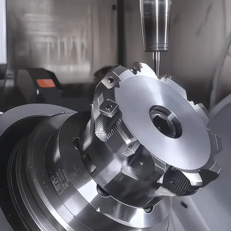
Chamfer mills are designed specifically to cut angled edges. They are commonly used for standard external chamfers, edge breaks, and repeated chamfer features on milled components. Because the cutter geometry already contains the required angle, the tool can often produce the chamfer efficiently with a simple toolpath.
The tool still needs proper selection. Cutter angle, diameter, flute design, coating, tool length, and material compatibility all matter. A chamfer mill that is too long may deflect or vibrate. A cutter that is not sharp enough may create burrs instead of a clean edge. For consistent chamfers, a stable and appropriate tool is more important than simply using a tool labeled as a chamfer cutter.
End Mills
End mills can be used to machine chamfers when a dedicated chamfer mill is not ideal. In some cases, the chamfer is generated by toolpath control rather than cutter angle alone. This can be useful for complex shapes, limited tool availability, or special geometry.
However, this method requires more programming control. Tool position, tool tilt, step-over, cutting depth, and engagement must be managed carefully. If the toolpath is not accurate, the chamfer width and angle may vary. End mills can be flexible, but flexibility often comes with higher programming responsibility.
Countersink Tools
Countersink tools are used mainly for hole entrances and fastener seating. They create a conical feature around a hole, often to allow a screw head to sit flush or to guide a pin or shaft during assembly. In this case, the countersink is not just a burr-removal operation, it is part of the assembly interface.
The tool angle must match the drawing requirement and fastener geometry. Common fastener-related countersinks may require specific included angles, and the opening diameter must be controlled. If the countersink does not match the fastener, the screw may not seat correctly even if the hole itself is accurate.
Deburring Tools
Deburring tools are useful when the only requirement is to remove sharp material from an edge. They can be manual, automated, or integrated into a CNC process. Their main advantage is speed and flexibility, especially for non-critical edges.
However, deburring tools do not provide the same level of dimensional control as a programmed CNC chamfer. If the drawing defines a measurable chamfer, deburring alone may not be enough. The designer and manufacturer must distinguish between “edge cleanup” and “controlled edge geometry.”
Grinding and Dedicated Chamfering Machines
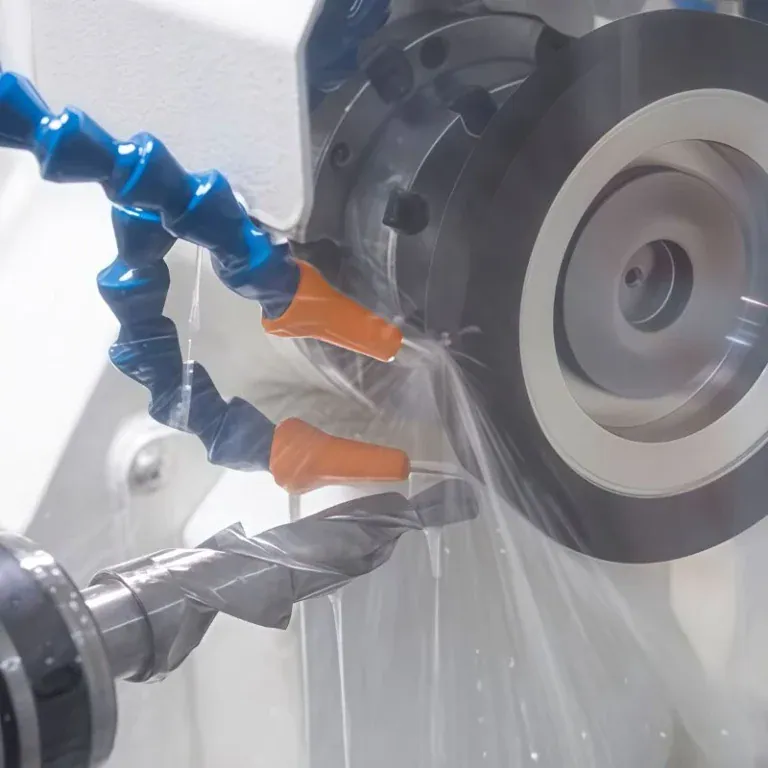
Grinding can be used when the material is hard, when the required finish is difficult to achieve through conventional cutting, or when the chamfer must meet a particular surface condition. Dedicated chamfering machines may be efficient for repetitive features, especially on bars, tubes, pipes, or standardized production parts.
The tradeoff is flexibility. Dedicated equipment can be fast for repeat work, but it may not be suitable for complex prototype parts or unusual geometry. CNC machining remains more flexible when the chamfer is part of a broader precision machining operation.
How Are Chamfer Size and Angle Controlled?
Chamfer size and angle are controlled through cutter geometry, tool position, programmed cutting depth, machine offsets, toolpath accuracy, and inspection feedback. The engineering drawing defines the intended geometry, while the machining process must convert that definition into a stable and repeatable edge. Good chamfer control requires matching the design requirement with realistic tooling, machine capability, material behavior, and inspection methods.
A 45° chamfer is common because it is easy to manufacture, but it is not required for every design. Chamfers can use different angles when they must support clearance, fastener seating, mating geometry, or insertion. Size also matters: a small edge break may only need a light chamfer, while a functional lead-in may require a larger one.
Choosing the Right Chamfer Size
Chamfer size should be chosen according to function and part scale. A very small chamfer may be enough to remove a sharp edge, but it may not provide meaningful assembly guidance. A large chamfer may improve lead-in behavior but can also remove material, reduce wall thickness, or interfere with adjacent features.
A practical approach is to use the smallest chamfer that satisfies the functional need. For example, a non-critical external edge may only require a small edge break, while a pin insertion feature may need a larger, more controlled chamfer. Oversizing chamfers can increase machining time and reduce part strength without adding value.
Selecting the Chamfer Angle
The chamfer angle should be selected based on geometry, function, and tooling. A 45° angle is efficient and widely supported by standard tools, but a 30°, 60°, or custom angle may be necessary for a specific assembly or fastener interface.
The angle should not be selected only for appearance. If a chamfer must guide a component into place, the angle should support that insertion. If it must provide clearance, the angle should match the space available. If it is only an edge break, a standard angle may be sufficient.
Toolpath and Cutting Depth
Toolpath and cutting depth determine how much material is removed and where the chamfer appears on the part. Incorrect tool offsets can make the chamfer too large or too small. Tool deflection can also affect cutting depth, especially when using long tools or machining hard materials.
For complex profiles, the toolpath must maintain consistent engagement along the edge. If the tool changes depth or orientation inconsistently, the chamfer width may vary. This is especially important on curved surfaces, housings, and multi-axis components.
Chamfer Tolerance and Cost
Chamfer tolerances should reflect function. A general edge break does not need the same tolerance as a fastener countersink, sealing-related feature, or assembly lead-in. Over-specifying tolerance can add machining time, inspection effort, and cost without improving part performance.
For production parts, tight chamfer tolerances may also require more frequent tool checks and more controlled inspection. If the chamfer does not affect fit or function, a looser and more practical specification is often better.
How Do Materials Affect Chamfer Machining?
Material properties strongly affect chamfer machining because hardness, ductility, toughness, thermal behavior, chip formation, and elastic deformation all influence edge quality. The same chamfer size and angle may behave differently in aluminum, stainless steel, titanium, copper, POM, PEEK, or nylon, so tool geometry and cutting parameters should be adapted to the material rather than copied from one job to another.
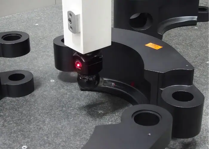
A clean chamfer requires stable shearing at the cutting edge. If the material smears, deforms, work-hardens, melts, or produces heavy burrs, the chamfer may fail even if the programmed geometry is correct. This is why material behavior must be considered together with tooling and cutting parameters.
Aluminum
Aluminum alloys are generally machinable and commonly used for precision CNC parts, housings, brackets, plates, and automation components. They can usually be chamfered efficiently, but soft or gummy aluminum conditions may lead to built-up edge, burr formation, or surface marks if the tool is not sharp or the cutting conditions are not suitable.
A sharp cutter, proper chip evacuation, stable feed rate, and suitable spindle speed are important for clean aluminum chamfers. If burrs appear along the chamfer edge, the cause may be tool wear, poor chip evacuation, or cutting conditions that push material instead of cutting it cleanly.
Steel and Stainless Steel
Steel and stainless steel usually require more attention to tool wear, rigidity, heat, and cutting force. Stainless steel can be especially challenging because it may work-harden under poor cutting conditions. If the chamfering tool rubs instead of cutting cleanly, the material can become harder locally, making the next pass more difficult.
For steel and stainless steel chamfers, tool coating, cutting speed, feed rate, coolant strategy, and cutter rigidity become important. A worn chamfer mill can cause burrs, poor surface finish, and angle inconsistency. Reducing tool overhang and using a stable setup can help maintain edge quality.
Engineering Plastics
Engineering plastics such as POM, PEEK, nylon, and PTFE behave differently from metals. They have lower stiffness, different thermal behavior, and higher sensitivity to clamping pressure and tool sharpness. A chamfer may appear inaccurate if the part deforms during clamping or if heat causes the edge to soften.
For plastic parts, sharp tooling and controlled cutting are especially important. Excessive heat can cause melting or rough edges, while excessive clamping force can distort the part before machining. For precision plastic chamfers, workholding strategy may be just as important as cutter selection.
Tool Wear and Cutting Conditions
Tool wear changes the actual cutting edge geometry. In chamfer machining, this can gradually change chamfer width, increase burr formation, and reduce surface quality. The effect may be small at first, but in production it can accumulate across many parts.
Cutting parameters should be selected to maintain stable material removal. Too aggressive a cut may create chatter or tool deflection, while too light a cut may cause rubbing instead of cutting. A stable chamfering process balances cutting load, edge quality, cycle time, and tool life.
What Are the Most Common CNC Chamfering Problems?
The most common CNC chamfering problems include uneven chamfer width, excessive burrs, poor surface finish, chamfer angle deviation, chatter, vibration, tool-wear-related dimensional drift, and variation between setups. These problems usually come from instability in tooling, workholding, machine condition, material behavior, or programming rather than from the chamfer concept itself.
A good troubleshooting process should identify whether the problem is caused by design, tool selection, machine setup, cutting parameters, or inspection. Simply changing the programmed chamfer dimension rarely solves the root cause if the tool is deflecting, the workpiece is moving, or the cutting edge is worn.
Uneven Chamfer Width
Uneven chamfer width is one of the most common problems. It may appear as a chamfer that starts narrow and becomes wider along the same edge, or as inconsistent chamfers across multiple similar features. Causes can include tool runout, worn cutting edges, tool deflection, unstable workholding, incorrect offsets, or surface variation from previous machining.
For example, if a drawing specifies a 1 mm chamfer and the actual part measures 1.0 mm on one side but 1.4 mm on another, the issue may not be the drawing. The first checks should be tool condition, tool runout, toolpath, workholding, and machine stability. A stable setup should produce consistent material removal before the program is adjusted.
Excessive Burr Formation
Burrs occur when the material is not cleanly sheared during cutting. They can appear along the edge of the chamfer, around hole entrances, or on the exit side of the toolpath. Burr formation is common in ductile materials, worn tools, unstable cutting, or poor chip evacuation.
The solution depends on the cause. Replacing a worn tool, increasing tool sharpness, adjusting feed and speed, improving coolant, changing cutting direction, or adding a finishing pass can all help. Simply making the chamfer larger may hide the burr temporarily but does not necessarily improve the process.
Poor Surface Finish
Poor chamfer surface finish can appear as roughness, scratches, chatter marks, tearing, or tool marks. It may be caused by tool wear, vibration, incorrect cutting speed, poor toolpath strategy, insufficient rigidity, or material behavior. Since chamfers are often located on visible edges, poor finish may affect both function and appearance.
A more stable tool setup can improve surface quality. This may include reducing tool overhang, using a more rigid holder, improving workholding, selecting a better cutting tool, or reducing unstable cutting engagement. If the chamfer is cosmetic, finish requirements should be clear before machining begins.
Chamfer Angle Deviation
Chamfer angle deviation occurs when the finished angle does not match the drawing. This can happen if the tool angle is incorrect, the tool is worn, the tool offset is wrong, or the toolpath does not match the intended geometry. It can also happen when an end mill is used to generate a chamfer through interpolation and the programming is inaccurate.
Angle deviation is especially important for countersinks and mating features. If the angle does not match the fastener or assembly requirement, the part may not function properly even if the edge looks visually acceptable.
Chatter and Vibration
Chatter and vibration can create visible marks, inconsistent chamfer width, poor surface finish, and dimensional variation. They are often caused by excessive tool overhang, weak workholding, high cutting load, machine looseness, or unsuitable cutting parameters.
Reducing chatter usually requires improving system rigidity. Shorter tools, better holders, stronger fixturing, reduced cutting load, and optimized feeds and speeds can all help. If the chamfer is located deep inside a pocket, design changes that improve tool access may be more effective than forcing a long tool to reach the feature.
Tool Wear and Dimensional Variation
Tool wear gradually changes chamfer quality during production. A tool may produce acceptable parts at the beginning of a batch but drift later as the cutting edge deteriorates. The chamfer may become rougher, wider, more burred, or less consistent.
For production parts, tool-life management is important. Periodic inspection, tool replacement intervals, and monitoring of burrs or surface finish can help prevent late-batch quality issues. If chamfer consistency is critical, inspection should not be limited to the first part only.
How Are CNC Chamfers Inspected?
CNC chamfers are inspected by checking the geometry and edge condition that matter to the part function, including chamfer width, angle, depth, position, burr condition, and surface quality. The inspection method should match the drawing tolerance and functional importance of the chamfer rather than applying the same measurement approach to every edge.
A non-critical edge break may only require visual confirmation that sharp edges and burrs have been removed. A functional chamfer used for assembly, fastener seating, or precision clearance may require more detailed measurement with a gauge, optical comparator, or CMM.
Chamfer Gauges
Chamfer gauges provide a fast way to check chamfer size in production. They are useful for common chamfer dimensions and can help operators verify whether an edge is within an acceptable range without using more complex equipment.
However, chamfer gauges may not be suitable for every geometry. Small internal features, complex contours, or tight positional requirements may require a different inspection method. Gauge selection should match the chamfer type.
Bevel Protractors
Bevel protractors are useful for checking chamfer angles on accessible features. They are relatively simple tools and can be effective when the main concern is angular confirmation rather than full dimensional analysis.
Their limitation is accessibility and precision. For very small chamfers or complex geometries, a bevel protractor may not provide enough detail. In those cases, optical or CMM inspection may be more appropriate.
Optical Inspection
Optical comparators and vision systems can inspect chamfer profiles without physically contacting the part. This is useful for small edges, delicate features, or profile-based inspection. Optical inspection can show whether the chamfer angle, width, and profile match the expected geometry.
This method is especially useful when the chamfer is small or when contact measurement may be difficult. It also helps identify burrs, edge irregularities, and profile deviations.
CMM Inspection
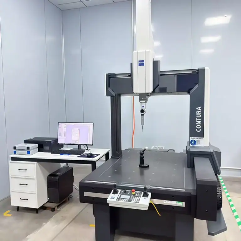
A CMM is useful when the chamfer must be checked relative to datums, holes, surfaces, or other precision features. It is appropriate for high-precision parts where the chamfer contributes to assembly or positioning.
However, CMM inspection should be reserved for features that require that level of control. Using high-precision inspection for a loose edge break can add time and cost without meaningful benefit.
Visual Inspection and Burr Checking
Visual inspection is useful for general edge quality, burrs, scratches, and obvious inconsistencies. It is commonly used for non-critical edge breaks and finishing checks.
However, visual inspection alone cannot verify a defined chamfer dimension or angle. If the drawing specifies measurable geometry, visual inspection should be combined with appropriate dimensional measurement.
When Should You Use a Chamfer?
A chamfer should be used when it provides a clear functional, manufacturing, assembly, safety, or finishing benefit. It is most valuable when the angled edge helps a mating part enter, removes a sharp edge, creates clearance, prepares a hole for a fastener, protects a vulnerable corner, or improves handling and surface treatment.

Chamfers are common in CNC machined shafts, housings, brackets, plates, fastener holes, threaded entrances, molds, dies, and automation parts. They can be small but important features that improve how the component performs in the real assembly.
Assembly and Insertion
Chamfers are useful when one component must enter another. A shaft entering a bore, a pin entering a locating hole, or a screw entering a threaded feature can all benefit from a controlled lead-in.
Without a chamfer, small misalignment can cause the mating part to catch on the sharp edge. A suitable chamfer helps guide the component into position and reduces assembly difficulty.
Edge Protection and Deburring
Chamfers protect edges by removing sharp corners that can chip, scratch, cut, or become damaged during handling. This is useful for parts that operators frequently touch or components that move through multiple production and assembly steps.
A light chamfer can also replace or reduce secondary deburring when the drawing allows it. However, if the chamfer is a controlled feature, machining and inspection should still follow the drawing requirement.
Clearance and Fastener Seating
Chamfers can create clearance for mating geometry, tool access, or fastener heads. Hole chamfers and countersinks are particularly important when screws, bolts, pins, or shafts interact with the feature.
A controlled countersink can determine whether a screw sits flush, too high, or too deep. This makes the chamfer a functional part of the assembly rather than a simple finishing detail.
Surface Treatment and Appearance
Chamfers can improve the consistency of coated, anodized, plated, painted, or polished edges. Sharp edges are more prone to coating inconsistency, edge buildup, or damage.
For visible parts, chamfers can also improve appearance by creating a clean and intentional edge condition. This is common in electronics housings, automation covers, brackets, and machined consumer-facing parts.
Chamfer vs. Fillet vs. Bevel vs. Deburring
Chamfers, fillets, bevels, and deburring are all related to edge treatment, but they create different geometries and solve different manufacturing problems. A chamfer creates a straight angled plane, a fillet creates a curved radius, a bevel generally describes an angled edge or surface, and deburring removes unwanted sharp material left by machining.
These terms are sometimes used loosely, but engineering drawings should be precise. A drawing that requires a fillet cannot be satisfied by a chamfer, and a defined chamfer cannot always be replaced by basic deburring.
| Feature | Geometry | Typical Purpose |
| Chamfer | Straight angled surface | Assembly, clearance, edge protection |
| Fillet | Curved radius | Smooth transition, stress management |
| Bevel | Angled edge or surface | Edge preparation, sloped geometry |
| Deburring | Removal of sharp material | Edge cleanup |
Chamfer vs. Fillet
A chamfer creates a flat angled transition, while a fillet creates a smooth radius. Chamfers are often easier to machine on external edges, while fillets may be preferred where a rounded transition is required.
In stress-sensitive areas, a fillet may be more appropriate because it provides a smoother transition. For assembly lead-ins or edge breaks, a chamfer may be simpler and more practical.
Chamfer vs. Bevel
A bevel is often a broader term for an angled edge or surface. A chamfer is usually a smaller, more specific edge treatment. In some industries, the terms may overlap, which is why the drawing geometry matters most.
Instead of relying only on terminology, engineers should define size, angle, and location. That makes the manufacturing requirement clear regardless of the word used.
Chamfer vs. Deburring
Deburring removes unwanted sharp material, while chamfering creates a defined geometry. A deburred edge may not have a consistent angle or size.
If the drawing only requires sharp edges to be removed, deburring may be sufficient. If the drawing defines C0.5 or 1 × 45°, a controlled chamfer is required.
FAQs
What Is The Difference Between Fillet And Chamfer Machining?
A chamfer creates a straight angled surface by removing material from an edge, while a fillet creates a curved transition with a defined radius. Chamfers are commonly used for edge breaking, assembly guidance, clearance, and fastener-related features. Fillets are often selected when a smooth transition is required. The choice depends on geometry, available space, function, tooling, and machining requirements.
What Is A Chamfer Vs Bevel?
A chamfer generally refers to a smaller angled edge created by removing material from a corner, while a bevel can describe a larger angled edge or surface preparation. The terminology can overlap between industries, so the actual dimensions, angle, location, and tolerance on the engineering drawing are more important than the terminology itself.
Are Chamfers Always 45 Degrees?
No. A 45° chamfer is common because it is easy to specify, machine, and inspect, but chamfers can use different angles when required by assembly clearance, fastener geometry, mating components, or other functional requirements. The correct angle should be determined by the design function rather than assuming that every chamfer must be 45°.
What Is Another Word For Chamfer?
Depending on the application, terms such as edge break, bevel, or angled edge may sometimes be used, but they are not always exact technical synonyms. A chamfer specifically describes a straight angled transition created by removing material from an edge. On engineering drawings, the intended geometry should always be clearly defined.
How To Chamfer On A Milling Machine?
To chamfer an edge on a milling machine, select a suitable chamfer mill or other cutting tool, establish the workpiece datum, and program the required toolpath, angle, and cutting depth. Tool rigidity, runout, feed rate, spindle speed, material, and tool access should be controlled to prevent uneven chamfer width, burrs, chatter, or poor surface finish. The completed chamfer should then be inspected against the drawing requirement.
Conclusion
Chamfer machining may look like a small detail, but it has a direct effect on assembly, edge quality, handling safety, fastener fit, surface finishing, and manufacturing cost. A reliable chamfer requires the correct geometry, tooling, machining method, workholding, cutting parameters, material strategy, drawing specification, and inspection method to work together. The best chamfer is not the largest or tightest one, but the one that performs its function while remaining practical and repeatable to manufacture.
At TiRapid, we provide precision CNC machining and manufacturing services for components requiring controlled chamfers, tight dimensional tolerances, complex geometries, and reliable surface quality. Our DFM analysis, CNC milling and turning, tooling selection, finishing processes, and quality inspection help ensure chamfered features are manufacturable, consistent, and ready for real-world assembly and use.