Undercut machining creates recessed, hidden, or back-facing features that a standard straight-shank cutter cannot reach from the primary machining direction. The main challenge is usually not removing the material, but giving the cutting edge enough access while keeping the tool shank and holder clear of the surrounding geometry.
This guide explains how undercuts are machined, which cutters suit common features, how tool access affects 3-axis and 5-axis strategies, and what design choices improve accuracy and manufacturability. It also covers tolerances, materials, common machining problems, applications, and cost.
What Is Undercut Machining?
An undercut is a feature located behind, beneath, or beside another surface where a conventional end mill cannot approach directly. It may appear as an internal groove, dovetail, retaining feature, back-side recess, or another geometry hidden from a normal top-down tool path.
Undercut machining therefore depends on two things at the same time: the shape of the cutting edge and the route the entire tool assembly must follow to reach the feature.

What Makes A Feature An Undercut?
A vertical wall, open pocket, or through-slot can usually be machined directly with a standard end mill. An internal side groove or back-tapered surface is different because another section of the part blocks the normal cutting direction.
The cutting head may physically fit inside the feature while the shank or tool holder does not. For that reason, checking cutter diameter alone is not enough. The available entry path and clearance around the complete tool assembly determine whether the geometry is realistically machinable.
This makes undercuts fundamentally an accessibility problem. Once access is confirmed, cutter geometry, rigidity, tolerance, and surface finish determine how difficult the operation will be.
When Is An Undercut Functionally Necessary?
Undercuts are useful when the geometry provides a clear mechanical function. Typical reasons include retaining another component, creating a locking feature, providing sealing space, clearing a mating part, or allowing assembly that would not work with a straight wall.
For example, T-shaped grooves can retain mounting hardware, dovetails can provide guided or locking engagement, and O-ring grooves can create controlled sealing interfaces. Relief features may provide clearance near shoulders, threads, or mating surfaces.
The design should therefore start with function. Adding a hidden feature that provides little functional value can introduce specialty tooling, more programming, additional setups, and harder inspection without improving the part.
Common Undercut Features In CNC Parts
Undercuts can be internal or external, but manufacturing decisions are more often driven by feature shape and cutter access. T-slots, dovetails, one-sided grooves, curved recesses, keyseat features, and reliefs are among the most common forms.
Each geometry places different demands on cutter profile, entry width, reach, and rigidity.
T-Slot And Keyseat Undercuts
A T-slot typically begins with a conventional straight slot. A T-slot cutter then passes through that opening and cuts laterally below the upper wall, creating a wider hidden section.
The important design relationship is between the entry slot and the cutter shank. The cutting head can be wider than the opening, but the shank must still pass through the slot with adequate clearance.
Keyseat cutters use a similar principle. Their smaller neck or shank provides access while the wider cutting section forms an internal groove. These tools are useful for retaining grooves, keyed features, and other recessed profiles.
Dovetail And Tapered Undercuts
Dovetail features contain angled sidewalls and require a cutter with a matching profile. They are commonly used for sliding interfaces, locating features, retaining structures, and mechanically locked joints.
Standard cutter angles are preferable because they are easier to source and replace. Published tooling guidance commonly references 45°, 60°, and 90° dovetail cutters, while non-standard angles may require custom tooling.
The cutter must also have enough cutting length to reach the full depth without forcing the neck or holder into the surrounding material.
One-Sided And Curved Undercuts
Curved and back-side features often use lollipop or spherical undercut cutters. Their rounded cutting heads and reduced necks allow the tool to reach around edges and machine surfaces that a conventional end mill cannot contact.
They are useful for rounded internal grooves, contoured surfaces, back-tapered areas, and difficult-to-access edges.
The trade-off is stiffness. A smaller neck improves access but reduces rigidity, so deep engagement or long reach can increase deflection and chatter.
Relief And O-Ring Groove Features
Relief undercuts are often added near shoulders, threads, bearing locations, or mating surfaces to provide clearance for another component or manufacturing operation. O-ring grooves provide controlled geometry for seals and must match the dimensional needs of the sealing system.
Not every groove is an undercut. An open groove that a standard tool can reach directly may simply be a conventional machined slot.
The distinction matters because true undercuts introduce access constraints that affect tooling, setup, inspection, and cost.
How Does Undercut Machining Work?
There is no single fixed process for every undercut. The machining sequence depends on feature location, entry direction, tool clearance, depth, material, and tolerance.
A practical strategy is to confirm access first, machine conventional geometry next, and leave the hidden feature for a suitable specialty cutter or multi-axis operation.
Review Geometry And Tool Access
The first step is to identify where the cutting edge must reach and how it will get there. The programmer needs to consider the opening size, surrounding walls, feature depth, approach direction, and available holder clearance.
This review should happen before selecting exact cutting parameters. A feature with no physical entry path cannot be solved by reducing feed rate or choosing a more rigid tool.
For internal features, an open edge, through-slot, or suitable access hole may be required. Completely enclosed undercuts can require a design change or a different process.
Machine The Accessible Geometry First
Standard end mills are normally used first to remove accessible material and establish pockets, slots, holes, and entry paths.
The specialty cutter is introduced only after sufficient clearance exists. A T-slot cutter, for example, cannot create its own narrow entry channel because its cutting head is larger than its shank.
This sequence keeps material removal efficient while limiting expensive specialty tooling to the feature that actually requires it.
Finish, Deburr And Inspect The Undercut
Finishing passes bring the undercut to its final width, depth, angle, radius, and location. Because these features are often recessed, cutting stability becomes especially important during the final pass.
Deburring may also be harder than on exposed geometry. A burr left behind an internal lip or around a hidden groove can interfere with assembly even when the main dimensions are correct.
Inspection must therefore be planned with the machining process. A feature that is difficult for a cutter to reach may also be difficult for a conventional measuring tool to reach.
Tools Used For Undercut Machining
Undercut cutters are selected according to feature profile and access. The cutting head must generate the required geometry, while the neck, shank, and holder must fit through the available space without collision.
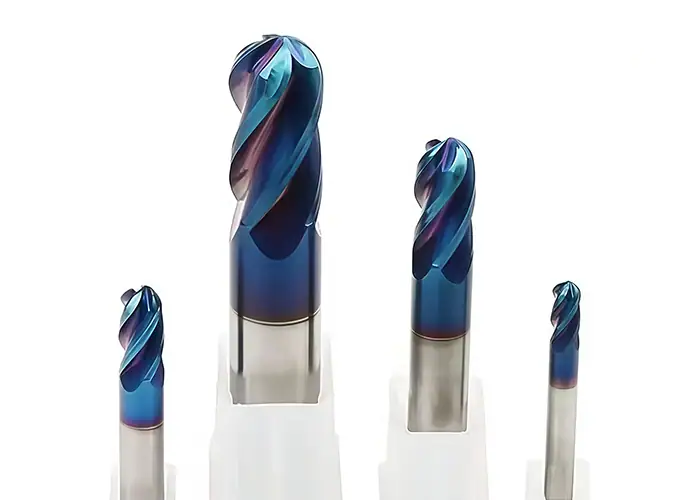
The three most common groups are T-slot or keyseat cutters, dovetail cutters, and lollipop-style undercut end mills.
T-Slot And Keyseat Cutters
T-slot cutters use a disc-like cutting head mounted on a smaller shank. The head creates the wider hidden region after the shank has passed through the entry slot.
Their important dimensions include head diameter, cutting width, shank diameter, and usable reach. These dimensions should be checked against the CAD geometry before the design is released.
When an entry opening is only large enough for the cutting width but not the shank, the cutter cannot reach the feature.
Dovetail Cutters
Dovetail cutters have angled cutting edges that generate tapered sidewalls. They are efficient when the design angle matches a readily available cutter.
Using standard cutter geometry generally reduces sourcing time, tool cost, and replacement risk. A custom dovetail angle can be manufactured, but it makes an otherwise straightforward feature more specialized.
Tool reach also needs attention because the cutting section must cover the required depth without creating holder interference.
Lollipop And Undercut End Mills
Lollipop cutters have spherical or near-spherical heads attached to a reduced neck. This geometry gives them better access around curved surfaces and behind local obstructions.
They are particularly useful when the cutter must approach the feature from several angles or blend a curved undercut.
Their flexibility is also their limitation. Thin necks and long reaches reduce stiffness, making light, stable cutting conditions more important when surface finish or dimensional consistency is critical.
Tool Access Determines Whether An Undercut Is Machinable
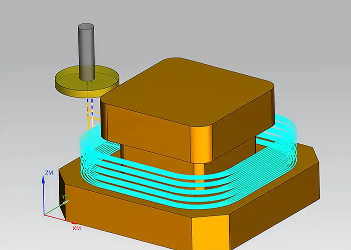
Tool access is the central design constraint in undercut machining. A CAD model may contain geometrically valid surfaces that no practical cutter can reach without colliding with another part of the component.
The design should therefore be evaluated around the cutter’s full movement, not just the final shape of the feature.
Entry Path And Shank Clearance
The entry opening must allow the tool shank to reach the cutting position without rubbing adjacent surfaces.
A useful design principle is simple: design the access path before finalizing the hidden profile. For T-slot features, the slot must accommodate the shank even though the cutting head is larger.
Providing reasonable clearance also makes programming safer and reduces the chance that minor tool or setup variation causes contact with the part.
Tool Reach And Undercut Depth
A cutter that is long enough is not automatically rigid enough.
As tool reach increases, cutting forces act farther from the holder. The tool becomes more sensitive to bending and vibration, which can leave marks on the feature or create dimensional variation.
Deep undercuts should therefore be justified by function. Reducing unnecessary depth can permit a shorter, stiffer tool and often improves both machining reliability and finish.
Holder And Workpiece Interference
Tool-access checks should include the holder and, where relevant, the spindle nose. A cutter head and shank may clear the feature while the larger holder collides with a nearby wall.
This is especially important in deep pockets and internal structures where surrounding surfaces narrow the approach envelope.
CAM simulation can identify many potential collisions, but it cannot make physically inaccessible geometry manufacturable. The CAD design still needs adequate clearance.
3-Axis Vs 5-Axis Undercut Machining
An undercut does not automatically require 5-axis machining. Many straightforward features can be produced efficiently on a 3-axis mill with suitable cutters and access.
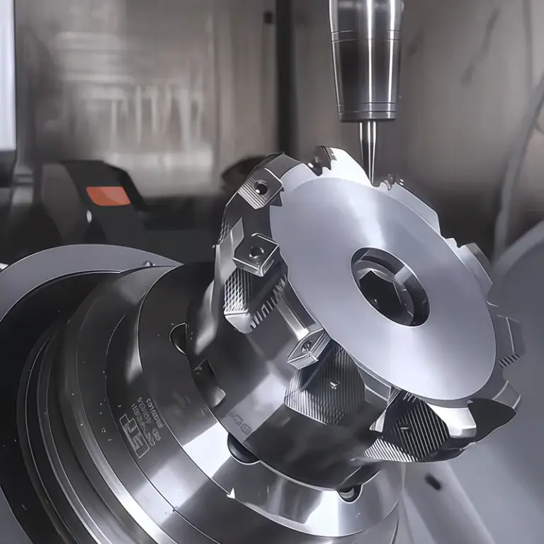
Five-axis machining becomes valuable when tool orientation itself needs to change to reach the geometry or to avoid excessive tool length.
When 3-Axis CNC Is Enough
Three-axis machining works well for features with a clear straight-line entry path, such as accessible T-slots, side grooves, shaft reliefs, and open-edge undercuts.
A specialty cutter can enter through a slot or from the side, move into the recessed area, and machine the final profile. Features on different faces may require repositioning the workpiece.
For simple geometry, this approach can be more economical than introducing a more complex machine purely because the part contains an undercut.
When 5-Axis CNC Makes More Sense
Five-axis machining allows the tool or workpiece to change orientation, improving access to hidden surfaces, angled features, and curved geometry.
It can also allow a shorter cutter to approach the feature from a better direction. Shorter tools are generally more rigid, which can improve machining stability and reduce the need for repeated setups.
Complex aerospace housings, medical components, and parts with undercuts in several orientations are typical situations where this flexibility becomes useful.
When EDM Or A Design Change Is Better
Some geometry remains impractical for milling even with additional axes. Completely enclosed regions, very sharp internal details, or inaccessible features in hard conductive materials may be better suited to electrical discharge machining.
A design change can be even more effective. Splitting one highly constrained component into two simpler machined pieces may remove the undercut altogether.
The correct decision should compare function, tolerance, production quantity, assembly requirements, and total manufacturing cost rather than assuming every feature must remain exactly as modeled.
Design Rules For Better Undercut Machining
Good undercut design reduces special tooling, long-reach cutting, repeated setups, and difficult inspection. The best improvements usually come from making the geometry compatible with existing manufacturing tools.
Tool access should therefore be considered during CAD design, not after the part has already been released for production.
Design The Access Path Before The Undercut
Every hidden feature needs a realistic route for the cutter.
An internal undercut may require an open end, through-slot, access hole, or enough side clearance for the cutting head and shank. If no route exists, the design may need another process or a split-part approach.
Access should also support tool withdrawal and chip evacuation, not only tool entry.
Keep Depth Within A Practical Tool Reach
Deeper features require greater tool reach, which normally reduces stiffness and increases the chance of chatter.
A feature may be theoretically reachable with a custom long-neck cutter yet still be difficult to machine consistently. Standard tooling guidance also shows that each cutter style has physical reach limits.
Reducing depth where function allows can shorten cycle time and improve dimensional stability without changing the purpose of the feature.
Use Standard Cutter Geometry Where Possible
Standard T-slot widths, common dovetail angles, practical corner radii, and readily available cutter sizes make the process easier to plan.
Custom profiles are sometimes necessary, but they increase tooling cost and may add lead time. Standard tooling also makes replacement easier during repeat production.
Standardizing similar undercuts within the same part can also reduce tool changes.
Avoid Unnecessary Sharp Internal Corners
Milling tools have physical cutting radii, so a perfectly sharp internal corner is usually not produced directly by a rotating cutter.
Requiring a zero-radius corner can introduce an additional machining method, including EDM in some cases.
Allowing a functional radius that matches practical tooling makes the feature easier to machine and often improves local stress behavior as well.
Tolerances And Accuracy In Undercut Machining
Undercut tolerances must account for the way the feature is reached. Thin-neck cutters, long overhangs, hidden surfaces, and multiple setups can make these features less forgiving than open pockets.
Critical dimensions should therefore be tied to functional requirements rather than assigning the same tight tolerance to the entire undercut.
Which Dimensions Matter Most?
Depending on the design, important dimensions can include groove width, undercut depth, dovetail angle, corner radius, and position relative to a datum or mating feature.
A retaining groove may depend strongly on width and location, while a dovetail interface may be more sensitive to angle and mating geometry.
The drawing should communicate which dimensions control fit, sealing, assembly, or movement so manufacturing effort can be focused where it matters.
Tool Deflection And Chatter
Undercut tools often place the cutting edge farther from the main support of the holder. This increases sensitivity to deflection and vibration.
Deflection can shift the effective cutting position and change feature depth or width. Chatter can produce visible marks, unstable dimensions, and poor surface finish.
A shorter tool, reduced overhang, stable workholding, suitable toolpath, and controlled cutting conditions generally provide better results than trying to compensate for a weak setup through inspection alone.
Inspecting Hidden Features
Inspection access can be as difficult as machining access.
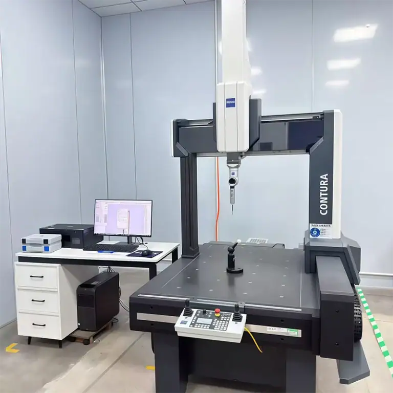
External dimensions may be easy to check with conventional instruments, while an internal groove or back-side surface may require a special gauge, coordinate measurement strategy, optical method, or indirect functional check.
Designers should therefore consider how a critical undercut will be measured before assigning very tight tolerances to surfaces that are difficult to access.
How Material Affects Undercut Machining
Undercuts can be machined in aluminum, steels, stainless steels, titanium, copper alloys, and engineering plastics, but material behavior changes cutting force, heat, tool wear, burr formation, and feature stability. Hardness, elasticity, and thermal behavior are particularly relevant when the tool is already limited by access or rigidity.
| Material | Machining Behavior | Main Undercut Concern |
| Aluminum | Generally easy to machine | Burrs and thin-feature stability |
| Carbon / Alloy Steel | Higher cutting forces | Tool rigidity and wear |
| Stainless Steel | Can work harden | Heat and cutting stability |
| Titanium | Retains heat near the cutting zone | Tool wear and thermal control |
| Copper / Brass | Generally machinable | Burr formation and finish |
| Engineering Plastics | Lower stiffness | Heat and deformation |
Material selection should remain driven by the part’s functional requirements. The machining strategy can then be adjusted around the material rather than choosing an inferior material simply because an undercut is present.
Common Undercut Machining Problems
Most undercut failures come from the interaction between geometry, access, cutter rigidity, toolpath, and material. Small changes to any of these factors can have a noticeable effect because the cutter is working in a restricted region.
The most common issues are chatter, poor finish, difficult deburring, and collision risk.
Chatter And Tool Deflection
Long-reach or thin-neck cutters are naturally more flexible. Cutting forces can push the tool away from the programmed position or excite vibration.
This may produce inconsistent depth, visible chatter marks, and variation along the feature.
Improving access so a shorter tool can be used is often more effective than trying to solve the entire problem with cutting parameters.
Poor Surface Finish And Difficult Deburring
Chip evacuation is less predictable inside recessed regions, and chips can contact already machined surfaces.
Hidden edges can also retain burrs that are difficult to reach with standard deburring tools. This becomes particularly important where the feature mates with a seal, sliding component, or locating surface.
Providing access for finishing and deburring can prevent a nominally correct feature from creating problems during assembly.
Collision And Tool Access Errors
A programmed path may appear correct when only the cutter tip is considered, yet the neck, shank, or holder can strike adjacent geometry.
Complex undercuts therefore benefit from careful tool assembly definition and simulation before cutting.
Still, simulation is a verification tool rather than a replacement for manufacturable design. An impossible entry path remains impossible regardless of how accurately it is modeled.
Applications Of Undercut Machining
Undercut machining is used when compact packaging, mechanical retention, sealing, guided engagement, or hidden clearance requires geometry that standard top-down milling cannot create.
Typical applications appear in automotive, industrial equipment, medical devices, aerospace, automation, and electronics.
Automotive
Automotive components may use undercuts in transmission parts, shafts, retaining features, seal grooves, and mechanical interfaces.
These features can support torque transmission, component retention, assembly clearance, or fluid sealing.
Their design must account for cyclic loads and production repeatability as well as machinability.
Industrial Equipment
Gearboxes, fixtures, hydraulic equipment, machine components, and tooling frequently use T-slots, reliefs, keyseat features, and internal grooves.
Many of these features have direct assembly or alignment functions, making feature position as important as the shape itself.
For larger industrial parts, tool and holder access can become a major consideration because surrounding structures may restrict approach angles.
Medical
Medical equipment may require compact internal locking features, instrument interfaces, or recessed mating geometry.
Because these components can have demanding material, cleanliness, and functional requirements, the undercut should be designed around the specific product rather than treated as a generic medical feature.
When access is restricted, multi-axis machining can help reduce the number of setups required for complex bodies.
Aerospace
Aerospace parts often combine complex geometry, lightweight structures, difficult materials, and controlled tolerances.
Undercuts may appear in housings, brackets, retaining features, and other compact mechanical interfaces. Multi-axis machining can improve access where straight-line approaches are blocked.
The combination of difficult materials and thin or long tooling makes rigidity especially important.
Automation And Electronics
Automation systems and electronic assemblies often require compact housings, locating features, retaining grooves, connectors, and fixture interfaces.
Undercuts allow components to lock or locate without adding separate external hardware in some designs.
However, reducing part count only creates value when the integrated feature remains practical to machine and inspect.
What Makes Undercut Machining More Expensive?
An undercut is not automatically expensive, but restricted access often introduces additional operations that conventional geometry does not require. Specialty cutters, long-reach tools, extra setups, slower machining, and more complex inspection can all increase cost.
The cost impact depends more on manufacturing complexity than on the physical volume of material removed.
Special Tools And Additional Operations
A standard end mill is widely available and can often machine several features in one setup. An undercut may require a dedicated T-slot, dovetail, keyseat, or lollipop cutter.
Non-standard profiles can require custom tools, which add procurement time and cost.
Each extra tool can also add programming, tool changes, setup verification, and inspection.
Deep Or Difficult-To-Reach Features
Deep recesses increase the required tool reach and may force the use of smaller shanks or longer necks.
This reduces rigidity and can require lighter cutting conditions, increasing cycle time.
If access becomes sufficiently complex, a 5-axis strategy or additional workholding may be justified, but both should be compared against a simpler design before production.
Tight Tolerances On Hidden Geometry
Tighter tolerances generally demand more stable cutting, additional finishing, and more measurement.
These requirements become more expensive when the surface is hidden because both machining and inspection are less accessible.
Applying close tolerances only to functional dimensions is one of the simplest ways to keep an undercut manufacturable without compromising performance.
How To Decide Whether An Undercut Should Stay In The Design
An undercut should not be removed simply because it is harder to machine. Many undercuts provide important mechanical functions that justify the added manufacturing work.
The decision should balance function against tool access, cutter geometry, rigidity, tolerance, inspection, and cost.
Keep It When The Feature Has A Clear Function
Retaining grooves, sealing features, assembly locks, clearance reliefs, and torque-transfer features can provide real value.
When the undercut eliminates another component, improves packaging, or enables the required mechanical interface, the manufacturing complexity may be justified.
The goal should then be to make the necessary feature as accessible and standard as possible.
Simplify It When Tool Access Drives The Geometry
If the same function can be achieved with less depth, a larger access opening, a standard angle, or a larger radius, the simplified version will usually be easier to manufacture.
Opening one side of a feature can sometimes eliminate a difficult approach entirely.
These changes do not necessarily make the component less sophisticated. they make the design better aligned with the physical constraints of cutting tools.
Consider Alternatives When The Geometry Becomes Impractical
If an undercut requires excessive tool reach, multiple specialty cutters, repeated setups, or difficult inspection, the design should be reviewed before moving into production. At that point, the machining complexity may outweigh the functional value of keeping the feature in its original form.
Five-axis machining can improve access to angled or recessed areas, while EDM may be more suitable for sharp or deeply hidden features in conductive materials. In some cases, dividing the component into two simpler parts can remove the undercut entirely and make both machining and inspection easier.
The best approach is to compare the feature’s function with its manufacturing requirements. Tool access, cutter geometry, rigidity, tolerance, inspection difficulty, and overall production cost should all be considered before deciding whether to retain the original design or use an alternative manufacturing strategy.
FAQs
What Are The Downsides Of Having An Undercut?
Undercuts can increase machining complexity because they often require special cutters, longer tool reach, extra setups, or multi-axis access. They can also be harder to inspect and deburr. Deep or tightly toleranced undercuts may increase tool deflection, cycle time, and overall manufacturing cost.
What Is The Purpose Of An Undercut?
An undercut creates clearance or hidden geometry that cannot be produced with a simple straight wall. It may be used for retaining components, locking features, sealing grooves, assembly clearance, thread relief, or other mating requirements. The feature should provide a clear functional benefit that justifies the added machining complexity.
How Is An Undercut Machined?
Undercuts are usually machined after the accessible geometry has been completed. Specialty tools such as T-slot cutters, dovetail cutters, keyseat cutters, or lollipop cutters are then used to reach the recessed area. Complex features may require 5-axis machining, while EDM can be considered when conventional cutting tools cannot reach the geometry.
Conclusion
Good undercut machining starts with tool access. Cutter geometry, entry clearance, feature depth, tool rigidity, tolerance, and inspection all need to work together before machining begins. A complex undercut can be produced reliably when it matches practical tooling, while a small hidden feature can become expensive when access is poor or the design requires unnecessary reach and precision.
At TiRapid, we provide precision CNC machining and manufacturing services for complex metal and engineering plastic parts. Our capabilities support 3-axis and 5-axis CNC machining, challenging undercut features, material evaluation, dimensional inspection, and practical manufacturing feedback for prototypes and low-volume production.