
CNC turning is a core process in precision mechanical manufacturing, playing a decisive role in machining cylindrical components. Facing increasingly strict customer tolerances and compressed production schedules, optimizing cutting efficiency while ensuring dimensional accuracy and surface finish remains a top technical priority for process engineers and machine operators.
Dimensional Tolerance Control in Precision CNC Turning
Controlling component dimensions is the fundamental benchmark of turning operations. Factors influencing dimensional stability range from machine hardware condition and thermal expansion to workholding stability. Establishing standardized operating procedures is essential to prevent error accumulation.
Thermal Deformation Control in Machine Tools
During extended machining sessions, heat generated by friction in the spindle bearings and guide channels causes structural thermal expansion, shifting the relative position between the tool tip and the workpiece. Implementing a structured thermal management protocol helps mitigate these deviations:
- Spindle Warm-Up Protocol: Before beginning production every day or after prolonged downtime, perform a 15–30 minute low-speed warm-up cycle. This allows the spindle housing and lubrication oil to reach thermal equilibrium, ensuring runout stays within minimal boundaries once machining begins.
- Constant Temperature Management: Precision machining workshops must be equipped with climate control systems maintaining ambient temperatures within ±2°C. Stable room temperatures prevent bed structures, columns, and heavy castings from expanding or contracting throughout day-night temperature cycles.
- Thermal Compensation Adjustment: Utilize the CNC system’s thermal compensation module in tandem with online probes or thermal sensors. By measuring test arbors at regular intervals, real-time thermal drift data is fed into the controller to dynamically update tool offsets.
Systematically managing these thermal variables reduces temperature-induced machining errors by over 60%, establishing a solid foundation for continuous high-precision production.
Balancing Clamping Force and Workpiece Deformation
Mechanical pressure exerted during workholding is a frequent trigger for component distortion, particularly when machining thin-walled or slender geometries. Subtle variations in clamping force directly impact final part dimensions:
- Step-Down Hydraulic Chuck Pressure: Adjust holding forces dynamically according to the machining phase. During heavy roughing where high stock removal generates significant cutting forces, apply higher hydraulic pressure. Switch to reduced clamping force (lowered by 50%–70%) during finishing passes to prevent elastic springback upon unclamping.
- Custom Soft Jaws and Arc Contact: For critical outer diameters, bore customized soft jaws on the lathe prior to finishing. Increasing the contact area between the jaw surface and workpiece distributes mechanical clamping force evenly, eliminating localized indentation.
- Auxiliary Support Systems: When machining shafts with length-to-diameter ratios exceeding 6:1, chuck clamping alone lacks sufficient rigidity. Hydraulic tailstock live centers combined with steady rests or follow rests must be deployed to provide multi-point support and counteract deflection caused by tool push.
Striking the correct balance between workholding rigidity and component structural limits prevents out-of-spec scrap while improving process reliability without damaging part surfaces.
Tooling Selection and Cutting Parameter Optimization
Cutting tool performance governs cycle time, tool life, and surface integrity. Selecting the proper parameter combinations significantly reduces unit production costs.

Tool Material and Coating Matching
Physical properties vary dramatically across workpiece materials. Matching tool substrate and coating technology to the material’s hardness, toughness, and thermal conductivity is critical for maximizing productivity:
| Workpiece Material | Recommended Substrate | Coating Type | Performance Characteristics
|
| Carbon / Alloy Steel | Carbide (ISO P Class) | CVD (TiCN + Al₂O₃) | High wear resistance; suitable for high-speed wet and dry cutting. |
| Stainless Steel | Micrograin Carbide (ISO M) | PVD (TiAlN) | High coating toughness; prevents built-up edge (BUE) and workpiece adhesion. |
| Aluminum Alloy | PCD Diamond / Uncoated Carbide | None / DLC Coating | Ultra-smooth rake face; smooth chip evacuation; prevents chip welding. |
| High-Temp Superalloys | Ceramic / CBN | None / Specialized PVD | Superior hot-hardness; ideal for hard turning and difficult-to-cut metals. |
Selecting tailored tool combinations prevents early premature tool wear, increasing edge life by 30% to 80% and lowering per-part consumable expenses.
Harmonizing the Three Cutting Elements
Cutting speed (Vc), feed rate (f), and depth of cut (ap) interact directly to dictate Metal Removal Rate (MRR) and edge longevity. Setting parameters requires a balanced approach between throughput and quality:
- Rough Machining Strategy: The primary objective during roughing is maximizing volume removal per minute. Utilize a high depth of cut (ap = 2.0–5.0 mm), moderate feed rate (f = 0.25–0.4 mm/rev), and moderate cutting speed. This directs primary forces into the strongest part of the carbide insert.
- Finishing Machining Strategy: Finishing operations focus strictly on surface finish and dimensional accuracy. Apply a small depth of cut (ap = 0.1–0.3 mm), low feed rate (f = 0.05–0.12 mm/rev), and elevated surface speed. High cutting speed softens the shear zone to suppress BUE formation, while low feed rates minimize peak-to-valley crest heights.
- Constant Surface Speed (G96) Integration: Program Constant Surface Speed (G96) into the CNC controller. As the tool moves inward toward smaller diameters, the spindle speed automatically increases, maintaining optimum tool-tip cutting velocity across the face and preventing surface finish degradation.
Establishing cutting parameters through engineering principles rather than trial and error shortens overall cycle times by over 15% while safeguarding tool stability.
Troubleshooting Common Turning Defects
Defects such as chatter vibration, surface scratches, and edge chipping occur frequently during turning operations. Identifying root causes and implementing corrective actions reduces scrap rates significantly.
Chatter Vibration Diagnosis and Elimination
Cutting chatter is a self-excited vibration phenomenon that leaves noticeable wave patterns on finished surfaces and causes rapid edge chipping or catastrophic tool failure. Eliminating chatter requires increasing process dynamic stiffness:
- Reduce Tool Corner Radius: When turning flexible slender shafts or thin-walled cylinders, replace standard R0.8 mm inserts with R0.4 mm or R0.2 mm nose radii. Smaller nose radii significantly decrease radial cutting forces, lowering the likelihood of deflection-induced vibration.
- Optimize Lead Angle: Prefer tool holders with 93° or 90° lead angles over 45° or 75° variants. A 90°/93° lead angle directs the majority of cutting forces along the axis of the spindle—where rigidity is highest—rather than pushing radially against the workpiece.
- Adjust Spindle Speed: Upon detecting high-frequency chatter harmonics, adjust the spindle speed override switch by ±10% to ±15%. Shifting spindle RPM disrupts the frequency synchronization between the machine structure and tool engagement, breaking the resonance condition.
Eliminating chatter sources preserves visual surface quality and protects spindle bearings from high-frequency shock impacts.
Corrective Measures for Subpar Surface Roughness
High surface finish values are strict requirements in precision manufacturing. When targets require Ra 0.8 µm or Ra 0.4 µm, microscopic control of chip evacuation and edge engagement becomes necessary:
- Implement Wiper Inserts: Wiper inserts feature a small flat smoothing edge adjacent to the primary cutting radius. Operating at identical feed rates, wiper geometry shears down peak ridges left by previous passes, cutting surface roughness values in half or allowing double the feed rate at the same Ra target.
- Optimize Chip Breaking: For ductile materials like carbon or stainless steels, choose inserts with aggressive 3D chipbreaker geometries. Forcing chips to break cleanly into compact “C” shapes prevents continuous stringer chips from marring completed surfaces.
- Deploy High-Pressure Coolant (HPC): Upgrade traditional flood coolant to high-pressure systems operating above 70 bar. High-pressure liquid jets vaporize the heat barrier at the cutting zone, providing rapid cooling while physically blasting chips away from the cutting edge.
Fine-tuning chip formation and friction characteristics ensures consistent surface finish compliance, eliminating secondary hand-polishing or grinding processes.
Advanced Automation and High-Efficiency Turning Applications
Modern turning practices continue evolving toward automation and multi-tasking integration. Minimizing non-cutting auxiliary time is central to boosting plant output.
Tool Life Management and In-Process Probing
Unattended night-shift production and lights-out manufacturing require replacing manual tool inspection and micrometer measurements with automated tracking systems:
- Automated Tool Life Tracking: Activate tool life management modules inside the CNC unit. Set maximum cutting minutes or part-count limits based on empirical wear data. Once reached, the controller automatically indexes to a sister tool on the turret without operator intervention.
- Pre-Setters and In-Process Probes: Integrate optical tool pre-setters for automatic offset entry. Pair these with spindle- or turret-mounted wireless touch probes to measure critical workpiece diameters automatically after key operations, writing dimensional feedback directly into tool offset registers for closed-loop compensation.
Merging automated probing with real-time tool tracking prevents batch scrap incidents while increasing overall machine tool utilization rates by over 25%.
Swiss-Type Lathes and Multi-Tasking Turn-Mill Technology
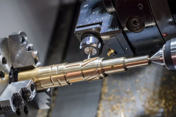
For complex geometries, slender shafts, and high-precision small parts, conventional single-spindle lathes face limits regarding setup times and rigidity. Advanced multi-tasking turning platforms overcome these barriers:
Swiss-Type CNC Lathes: Swiss-type automatic lathes feature a sliding headstock that feeds bar stock through a high-precision guide bushing. Because cutting forces occur within millimeters of the supporting bushing exit, radial deflection is virtually eliminated, enabling extraordinary rigidity when turning slender pins and long micro-shafts.
Turn-Mill Multi-Tasking Centers: By integrating Y-axis motion, sub-spindles, and live-driven tool turrets, turn-mill centers combine turning, off-center drilling, Y-axis milling, and tapping into a single platform. Components are transferred automatically between main and sub-spindles for complete front-and-back machining in a single setup, removing manual re-clamping errors and drastically reducing inter-machine queue times.
Adopting Swiss-type lathes and multi-tasking turn-mill technology represents the future of high-precision component manufacturing, delivering a competitive edge through complete single-setup processing.
















