
Tensile stress is the internal force per unit area produced when a material is pulled by an external load. It is calculated by dividing the applied tensile force by the original cross-sectional area. Engineers use tensile stress to determine how much pulling load a component carries, evaluate potential deformation, and assess whether its material is suitable for the application.
This guide explains the tensile stress formula, calculation methods, units, practical examples, and stress-strain behavior. It also compares tensile stress with tensile strength, yield strength.
What Is Tensile Stress?
Tensile stress is the internal force per unit cross-sectional area developed when an external load pulls a material in opposite directions. It indicates how strongly a component is being stretched and is commonly measured in megapascals (MPa) or pounds per square inch (psi).
When a metal rod is pulled from both ends, internal forces develop to resist the applied load. A larger tensile force produces greater stress, while a larger cross-sectional area distributes the same force over more material. Therefore, two components carrying identical loads may experience very different stress levels.
Tensile stress is important because excessive loading can cause elastic elongation, permanent deformation, or fracture. However, the calculated stress alone does not establish whether a component is safe. Engineers must compare it with relevant material properties, especially yield strength and ultimate tensile strength.
When Does Tensile Stress Occur?
Tensile stress occurs when a force attempts to stretch a material along its length. Typical examples include cables supporting suspended loads, bolts holding assemblies together, and mechanical rods transferring pulling forces. The stress develops within the material as it resists the applied tension.
Tensile stress can also occur in components exposed to bending. For example, one side of a loaded beam may experience tension while the opposite side experiences compression. The tensile stress distribution depends on the loading direction, cross-sectional geometry, and support conditions.
At lower stress levels, many metals recover their original dimensions when the load is removed. When loading exceeds the elastic limit, permanent deformation may begin. Further loading can produce necking, cracks, or fracture, depending on the material and operating conditions.
Tensile Stress vs. Tensile Strength
Tensile stress describes the force per unit area acting on a component, while tensile strength describes a material’s resistance to tensile loading. In engineering, tensile strength usually refers to the maximum engineering stress recorded during a standardized tensile test.
For example, a component may experience 120 MPa of tensile stress while its material has an ultimate tensile strength of 310 MPa. The applied stress is below the material’s maximum tested strength, but the part must still be evaluated against yield strength, fatigue, and other possible failure modes.
If you are asking what is tensile strength, the important distinction is that strength is a material property, while stress depends on the actual load and geometry. Both use MPa or psi, but they provide different information for mechanical design.
| Comparison | Tensile Stress | Tensile Strength |
| Meaning | Stress developed under pulling loads | Maximum engineering stress measured in a tensile test |
| Main variables | Applied force and cross-sectional area | Material grade, condition, and test requirements |
| Common unit | MPa or psi | MPa or psi |
| Engineering use | Calculate component loading | Evaluate material capacity |
| Typical question | How much stress is acting? | How much stress can the material withstand? |
What Is the Tensile Stress Formula?
The tensile stress formula is σ = F / A₀, where σ represents engineering tensile stress, F is the applied axial tensile force, and A₀ is the original cross-sectional area perpendicular to the force. The equation calculates average stress under direct axial tension.
Tensile Stress Formula:
σ = F / A₀
The formula applies most directly to straight components under centered axial loading. For a uniform rod, the original cross-sectional area can be calculated from its diameter. For rectangular components, the area is determined by multiplying width by thickness.
This equation provides nominal or average engineering stress. It does not automatically account for local stress concentrations around holes, threads, notches, or sharp corners. Complex components may require additional calculations or finite element analysis.
Tensile Stress Symbol and Units
The standard symbol for tensile stress is the Greek letter sigma, σ. Its SI unit is the pascal (Pa), equivalent to one newton per square meter. In engineering applications, megapascals are commonly used because component stresses are often relatively high.
One MPa equals 1,000,000 Pa or 1 N/mm². This relationship makes stress calculations straightforward when tensile force is measured in newtons and cross-sectional area is measured in square millimeters. US engineering drawings may use psi or ksi instead.
| Quantity | Symbol | Common Unit |
| Tensile stress | σ | MPa or psi |
| Tensile force | F | N or lbf |
| Original cross-sectional area | A₀ | mm² or in² |
| Tensile strain | ε | Dimensionless |
| Young’s modulus | E | GPa or psi |
| Ultimate tensile strength | UTS | MPa or psi |
For example, applying a 1,000 N load to a 10 mm² cross-section produces 100 MPa of tensile stress. Consistent units are essential because incorrect conversions can produce significant engineering errors.
How to Calculate Tensile Stress
Tensile stress is calculated by dividing the applied axial tensile force by the original load-bearing cross-sectional area. The calculation requires the force, the cross-sectional dimensions, and a consistent measurement system.
The process has three steps:
- Determine the applied tensile force in newtons.
- Calculate the original cross-sectional area in square millimeters.
- Divide force by area to obtain tensile stress in MPa.
For a rectangular section:
A₀ = Width × Thickness
For a solid circular section:
A₀ = π × d² / 4
For a hollow circular section:
A₀ = π × (D² − d²) / 4
Here, D is the outside diameter and d is the inside diameter. These equations calculate the area perpendicular to the applied tensile force.
The result is average axial stress, not necessarily the maximum local stress. If the component contains threads, holes, or combined loading conditions, engineers should evaluate the critical section separately.
Tensile Stress Calculation Examples
Tensile stress calculations demonstrate how the applied force and load-bearing area determine stress. The following examples assume centered axial loading and use the original cross-sectional area.
Example 1: Steel Rod
A solid steel rod has a diameter of 10 mm and carries a tensile force of 15,000 N.
Cross-sectional area:
A₀ = π × 10² / 4 = 78.54 mm²
Tensile stress:
σ = 15,000 / 78.54 = 190.99 MPa
Result: The steel rod experiences approximately 191 MPa of average tensile stress.
Example 2: Aluminum Bar
A rectangular aluminum bar is 20 mm wide and 5 mm thick. It carries a tensile force of 12,000 N.
Cross-sectional area:
A₀ = 20 × 5 = 100 mm²
Tensile stress:
σ = 12,000 / 100 = 120 MPa
Result: The aluminum bar experiences 120 MPa of average tensile stress.
Example 3: Flat Metal Plate
A flat metal plate has a load-bearing cross-section measuring 25 mm × 8 mm and carries a tensile force of 20,000 N.
Cross-sectional area:
A₀ = 25 × 8 = 200 mm²
Tensile stress:
σ = 20,000 / 200 = 100 MPa
Result: The metal plate experiences 100 MPa of average tensile stress.
| Example | Tensile Force | Cross-Sectional Area | Calculated Stress |
| Steel rod | 15,000 N | 78.54 mm² | 191 MPa |
| Aluminum bar | 12,000 N | 100 mm² | 120 MPa |
| Flat metal plate | 20,000 N | 200 mm² | 100 MPa |
These calculations show that increasing the force or reducing the cross-sectional area raises the average tensile stress. Whether the component remains safe depends on the material properties and actual operating requirements.
How Does Tensile Stress Relate to Tensile Strain?
Tensile stress measures the pulling force per unit area, while tensile strain measures the resulting elongation relative to the original length. In the linear elastic region, stress and strain are proportional through Young’s modulus, which represents material stiffness.
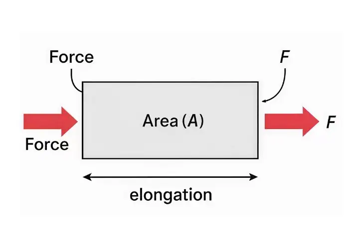
Stress and strain describe two connected aspects of material behavior. When a tensile load is applied, the material develops internal stress and changes length. The amount of elongation depends on the material’s stiffness and whether loading remains within the elastic range.
This relationship is important because a component can remain below its tensile strength while still deforming enough to affect performance. Excessive elongation may cause assembly misalignment, positioning errors, or changes in mechanical clearances.
Tensile Strain and Its Formula
Tensile strain is calculated by dividing the change in length by the original gauge length. It indicates relative elongation and allows deformation to be compared between specimens of different lengths.
Tensile Strain Formula:
ε = ΔL / L₀
Where:
ε = Engineering tensile strain
ΔL = Change in length
L₀ = Original gauge length
For example, a specimen with an original length of 100 mm stretches by 0.2 mm:
ε = 0.2 / 100 = 0.002 = 0.2%
The engineering tensile strain is 0.002, or 0.2%. Because strain is a ratio of two lengths, it has no physical unit. These measurements are collected during tensile testing to evaluate elastic and plastic deformation.
Understanding the Stress-Strain Curve
A stress-strain curve shows how a material deforms as tensile stress increases. Stress is plotted on the vertical axis, while strain is plotted on the horizontal axis. The curve describes the material’s response from initial loading through deformation and eventual fracture.
For many ductile metals, the tensile curve contains several important stages:
| Stage | Material Behavior | Engineering Significance |
| Linear elastic region | Recoverable deformation | Determines elastic modulus |
| Yielding | Permanent deformation begins | Establishes yield strength |
| Strain hardening | Stress rises during continued plastic deformation | Indicates strengthening during deformation |
| Ultimate tensile strength | Engineering stress reaches its maximum | Identifies the maximum tensile-test load |
| Necking and fracture | Localized thinning and eventual rupture | Describes final failure behavior |
The curve is produced from a controlled tensile test. During testing, the applied force and specimen elongation are measured and converted into engineering stress and strain. Metal testing commonly follows standards such as ASTM E8/E8M.
Not every material follows the same curve. Brittle materials can fracture with little plastic deformation, while engineering plastics may exhibit nonlinear and time-dependent behavior. Material-specific testing data is therefore necessary for reliable interpretation.
Young’s Modulus, Yield Strength, and Ultimate Tensile Strength
Young’s modulus measures elastic stiffness, yield strength identifies the onset of permanent deformation, and ultimate tensile strength describes the maximum engineering stress reached during a tensile test. Each property provides different information about material performance.
Within the linear elastic region, Hooke’s law is:
σ = E × ε
Where E is Young’s modulus. A higher modulus generally means less elastic strain under the same stress. Yield strength becomes particularly important when a component must retain its dimensions after loading.
Ultimate tensile strength, also called ultimate tensile stress in some references, is calculated using the maximum tensile force recorded during testing.
Tensile Strength Formula:
UTS = Fmax / A₀
The distinction between yield stress vs tensile stress is that yield stress identifies a material limit, while tensile stress describes the actual loading condition. A component may begin to deform permanently before reaching its ultimate tensile strength.
What Factors Affect Tensile Performance?
Tensile performance depends on material composition, microstructure, temperature, loading conditions, and part geometry. These factors influence material strength, deformation, ductility, and the likelihood of failure under tensile loading.
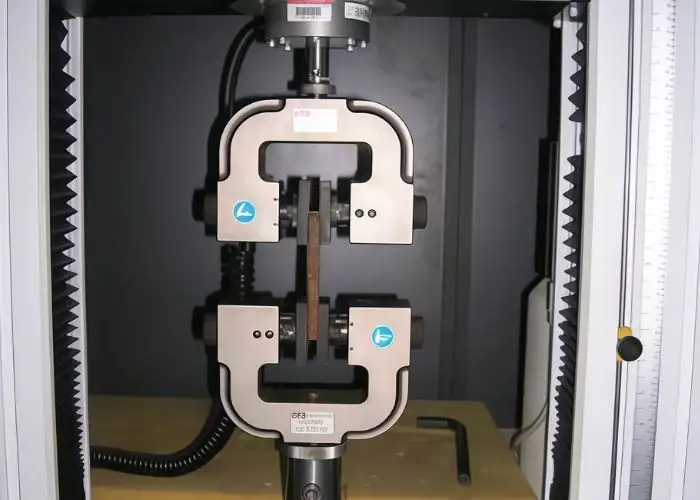
A material’s tensile properties can change significantly with heat treatment, processing history, surface condition, and internal defects. Published strength values usually represent specific material conditions and testing requirements rather than every possible finished component.
Geometry and service conditions are equally important. A component made from a strong material may still experience excessive stress near a hole, notch, or abrupt section transition. Reliable performance depends on the complete combination of material and design.
Material Properties and Microstructure
Material composition and microstructure influence tensile strength, yield behavior, and ductility. In steels, carbon content, alloying elements, and heat treatment determine important mechanical characteristics. Aluminum alloys also exhibit substantial differences between grades and tempers.
Grain size, precipitates, inclusions, and internal voids can affect how deformation and cracking develop. High tensile strength does not automatically indicate high fracture toughness or ductility, making material selection more complex than comparing strength values alone.
For CNC-machined components, material grade and condition must match the design requirements. Annealed stainless steel, hardened alloy steel, and heat-treated aluminum may have very different mechanical properties even when machined into similar geometries.
Temperature and Loading Conditions
Temperature influences tensile strength, yield strength, stiffness, and ductility. Many engineering metals lose strength at elevated temperatures, while some materials become more susceptible to brittle fracture at low temperatures. The actual effect depends on composition and material condition.
Repeated tensile loading can also cause fatigue damage. Components exposed to vibration, rotating machinery, or repeated mechanical movement may fail at stress levels below their ultimate tensile strength after sufficient loading cycles.
At elevated temperatures, sustained loading may produce creep, causing deformation to increase over time. Engineers should consider temperature, loading frequency, stress amplitude, operating duration, and expected service life.
Part Geometry and Stress Concentration
Part geometry affects tensile performance by controlling how the applied force is distributed. Holes, grooves, sharp corners, threads, and sudden changes in section thickness can generate local stress concentrations greater than the nominal calculated stress.
For example, a plate containing a hole has a reduced load-bearing section. The hole also changes the stress distribution around its boundary, creating locations where the local stress can be higher than the average value.
CNC machining allows precise control of fillets, section transitions, threads, and surface finish. These capabilities can help manufacture geometries intended to reduce stress concentrations, but the underlying design must still provide suitable load paths and adequate section thickness.
What Are the Real-World Applications of Tensile Stress?
Tensile stress calculations are used to evaluate components exposed to pulling loads, including cables, structural connections, fasteners, machinery, and manufactured parts. They help engineers assess loading, select materials, control deformation, and reduce failure risks.
In practice, tensile stress often acts together with bending, shear, torsion, or vibration. Engineers must understand how these loading conditions interact rather than assuming that every component experiences simple axial tension.
Tensile performance also matters in manufacturing because different processes influence geometry, material structure, and surface integrity. CNC machining, 3D printing, and injection molding introduce different considerations for load-bearing components.
Structural Components and Fasteners
Structural cables, tie rods, and tension members transfer pulling forces between connected elements. Engineers calculate nominal tensile stress and compare it with appropriate material limits, design factors, and relevant engineering standards.
Bolts and threaded fasteners are also subjected to tensile loading. Their effective tensile stress area is generally smaller than the area of the unthreaded shank because of thread geometry. Proper calculations must account for the relevant threaded section.
Fastener reliability also depends on preload, joint stiffness, fatigue resistance, and correct installation. Sufficient tensile strength alone does not guarantee a reliable connection if joint geometry or loading conditions are unsuitable.
Machinery and Mechanical Parts
Mechanical components such as actuator rods, lifting links, connecting members, and machine brackets may experience substantial tensile loading. Their geometry and material properties must support the required loads without excessive elongation or permanent deformation.
An actuator rod, for example, may experience axial tension during operation. If misalignment introduces additional bending, the maximum stress can exceed the average axial stress calculated using the basic formula.
Dimensional stability is especially important in precision equipment. Excessive elongation may affect positioning or alignment, while plastic deformation can prevent a component from functioning correctly even without fracture.
CNC Machining and Manufacturing Processes
CNC machining influences tensile performance through component geometry, surface condition, material state, and residual stress. Although machining does not normally increase a material’s bulk tensile strength, it can affect local stress concentrations and the initiation of surface cracks.
Features such as narrow grooves, threads, small radii, and abrupt section transitions require attention. Tool marks, burrs, and surface damage may increase crack initiation risks, particularly when components experience repeated tensile loading.
Engineers should consider material orientation, machining parameters, surface requirements, and inspection of critical features. Successful precision machining combines dimensional accuracy with manufacturing decisions that support the intended mechanical performance.
3D Printing and Injection Molding
3D-printed components may exhibit direction-dependent tensile properties because of layer bonding, build orientation, and manufacturing parameters. In some polymer printing methods, strength across layer interfaces can be lower than strength along the deposited material paths.
Build orientation, infill, polymer grade, and processing conditions influence how printed components resist tensile loading. Functional prototypes should therefore be tested under representative conditions when their performance depends on mechanical strength.
Injection-molded components introduce other factors, including fiber orientation, weld lines, cooling conditions, and processing-related defects. These can cause tensile performance to vary across a part, making actual component geometry and load direction important.
How Does Tensile Stress Influence Material Selection?
Tensile stress influences material selection by helping engineers determine whether a material can withstand expected loads without unacceptable deformation or failure. The appropriate material depends on strength, stiffness, ductility, operating conditions, weight, manufacturability, and cost.
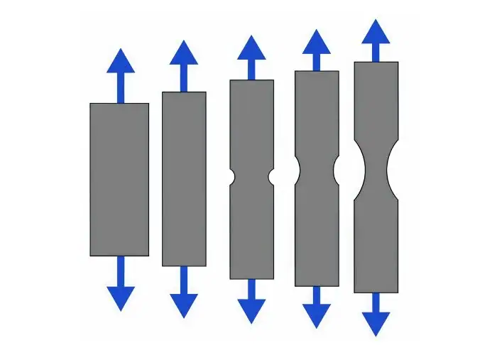
Material selection starts with identifying the component’s loading requirements. A precision fixture that must resist permanent deformation may require different material properties from a lightweight structural link or a part exposed to repeated tension.
For CNC-machined components, material choice also influences machining difficulty, achievable tolerances, dimensional stability, and production cost. Selecting the strongest available alloy is not always the most practical engineering decision.
Tensile Properties of Common Engineering Materials
Common engineering materials exhibit different tensile properties depending on alloy composition, heat treatment, temper, and product form. Aluminum alloys are widely used where weight and machinability matter, while steels provide a broad range of strength levels for mechanical applications.
Stainless steels offer corrosion resistance alongside mechanical performance. Titanium alloys provide high specific strength but generally require more demanding machining conditions. Engineering plastics offer lower density and useful chemical or electrical properties where their lower strength is acceptable.
The following table provides representative values for selected material conditions. Actual properties vary by specification, product form, processing history, and testing requirements.
| Material and Condition | Yield Strength (MPa) | Ultimate Tensile Strength (MPa) |
| Aluminum 6061-T6 | Approx. 276 | Approx. 310 |
| Aluminum 7075-T6 | Approx. 503 | Approx. 572 |
| Stainless Steel 304, annealed | Approx. 205 minimum | Approx. 515 minimum |
| Stainless Steel 316, annealed | Approx. 205 minimum | Approx. 515 minimum |
| Titanium Ti-6Al-4V, annealed | Approx. 880 | Approx. 950 |
These values are illustrative, not universal design allowables. Engineers should use the relevant material specification and certified mechanical properties when designing safety-critical or tightly controlled components.
Comparing Tensile Strength and Yield Strength
Yield strength is the more relevant limit when a component must avoid permanent deformation. Ultimate tensile strength represents the highest engineering tensile stress reached in a tensile test, but it should not be treated as an acceptable normal operating stress.
For example, 6061-T6 aluminum has a typical yield strength of approximately 276 MPa and an ultimate tensile strength of approximately 310 MPa. Permanent deformation can therefore begin before the material reaches its maximum engineering tensile strength.
This difference matters for CNC-machined brackets, precision fixtures, and mechanical connections. A component that remains intact but permanently stretches or bends may no longer meet its dimensional or functional requirements.
| Design Requirement | Relevant Property | Engineering Purpose |
| Prevent permanent deformation | Yield strength | Controls plastic deformation |
| Limit elastic deflection | Young’s modulus | Evaluates stiffness |
| Compare maximum tensile capacity | Ultimate tensile strength | Evaluates peak engineering stress |
| Resist repeated loading | Fatigue properties | Evaluates cyclic failure risks |
| Resist crack-related failure | Fracture toughness | Evaluates crack resistance |
Selecting Materials Based on Load and Manufacturing Requirements
Material selection should begin with expected loads, component geometry, operating temperature, and loading frequency. Engineers calculate relevant stresses and compare them with the material properties that govern the required performance.
Manufacturing requirements can influence the final choice. High-strength materials may improve load capacity but increase machining difficulty, tool wear, cost, or distortion risk. A material with moderate strength may be more suitable if it already satisfies the operating requirements.
A practical selection process includes:
- Identify maximum and repeated tensile loads.
- Calculate nominal stresses and assess stress concentrations.
- Compare calculated stresses with appropriate material limits.
- Evaluate stiffness, ductility, fatigue, and environmental requirements.
- Confirm machinability, achievable tolerances, surface finish, and cost.
The objective is to select a material that provides adequate mechanical performance and predictable manufacturing results without unnecessary strength, complexity, or cost.
FAQs
What Is Tensile And Compressive Stress?
Tensile stress develops when forces pull a material apart, while compressive stress develops when forces push it together. Both are measured as force per unit area, commonly in MPa. For example, a 10,000 N axial load applied to a 100 mm² section produces a nominal stress magnitude of 100 MPa in either direction. However, materials may respond differently to tension and compression. Slender components under compression can also experience buckling before reaching their material’s compressive strength.
What’s The Difference Between Tensile And Tension?
Tension refers to a pulling force acting on a component, while tensile describes a loading condition or material property associated with pulling. Tension is measured in newtons, while tensile stress is measured in MPa or psi. For example, a cable carrying 5,000 N of tension with a 50 mm² cross-sectional area experiences an average tensile stress of 100 MPa. This distinction helps engineers separate the externally applied force from the internal stress developed in the material.
What Does A High Tensile Stress Mean?
High tensile stress means a component experiences a relatively large pulling force per unit load-bearing area. Whether it is acceptable depends on material properties and operating conditions. For example, 300 MPa may exceed the typical yield strength of 6061-T6 aluminum but remain below that of 7075-T6 aluminum. Engineers must also consider stress concentrations, fatigue, temperature, and suitable design limits. A high nominal tensile stress does not automatically mean immediate fracture, but it may indicate increased deformation or failure risk.
Is Higher Tensile Strength Better?
Higher tensile strength is beneficial when a component must withstand greater pulling loads, but it is not always the best selection criterion. For example, 7075-T6 aluminum has a typical ultimate tensile strength of approximately 572 MPa, compared with about 310 MPa for 6061-T6. However, material selection also depends on corrosion resistance, ductility, fracture behavior, machinability, and cost. If a lower-strength material already meets the design requirements, choosing a stronger alloy may increase manufacturing costs without improving functional performance.
What Is Yield Strength Of A Material?
Yield strength is the stress at which a material begins to undergo permanent plastic deformation. For metals without a distinct yield point, engineers commonly use a 0.2% offset method to determine proof strength. For example, a material with a yield strength of 250 MPa may begin permanent deformation when the relevant local stress reaches that level under appropriate conditions. Yield strength is particularly important for precision components because permanent changes in geometry can affect assembly accuracy and mechanical function before fracture occurs.
Conclusion
Tensile stress describes how pulling forces are distributed through a material and provides a foundation for evaluating mechanical component performance. The basic formula is straightforward, but reliable design also requires understanding tensile strain, yield strength, ultimate tensile strength, stress concentrations, and operating conditions. By combining accurate calculations with suitable material properties and effective component design, engineers can reduce deformation risks, improve reliability, and avoid unnecessary material or manufacturing costs.
At TiRapid, we provide precision CNC machining and manufacturing services for custom metal and plastic components. Through material selection support, controlled machining processes, and dimensional quality inspection, we help customers manufacture precision parts that meet their design and application requirements.
















