
As a cornerstone of precision machinery manufacturing, CNC turning uses computer numerical control to guide cutting tools against rotating workpieces. From aerospace shafts to miniature threads for medical devices, turning technology underpins critical component production. Mastering machining details and parameter adjustments is essential for boosting pass rates and cutting unit costs.
Key Factors Governing Dimensional Tolerance and Surface Roughness
Part quality relies directly on machine condition, tool selection, and cutting parameters. Balancing these three elements drives throughput and quality improvements.
Machine Rigidity and Thermal Deformation Control
Structural stability serves as the bedrock of dimensional precision.
Heat generated by spindle bearings and guide rail friction during high-speed operation causes localized thermal expansion, altering the precise position of the tool tip relative to the workpiece.
- Bed Structure Selection: Slant-bed designs offer superior bending and torsional rigidity compared to flat beds, featuring shorter chip-evacuation paths that minimize heat accumulation around the headstock.
- Spindle Thermal Elongation Compensation: Oil-chillers maintain constant spindle bearing temperatures, while thermal expansion coefficients programmed into the CNC system compensate for growth during continuous high-volume production.
- Drivetrain Backlash Maintenance: Periodic checks on ball screw preload and guide rail runner blocks eliminate mechanical backlash, locking in repeatable positioning accuracy within 0.003 mm.
Once peak machine condition is secured, pairing it with optimal tooling unlocks maximum machining efficiency.
Tool Geometry and Material Matching
Material behavior varies drastically under the stress of cutting, making targeted tool material and geometry selection vital.
Coated carbide inserts retain high red-hardness in high-temperature cutting zones, slowing tip wear.
- Coating Material Selection: TiAlN-coated inserts excel on stainless steel and superalloys, whereas uncoated, ultra-fine micrograin carbide inserts with polished flutes perform best on non-ferrous metals like aluminum alloys.
- Nose Radius (R-Corner) Tuning: Roughing calls for a larger nose radius (such as R0.8) to withstand heavy cut depths and reinforce tip strength; finishing uses a smaller radius (R0.2 or R0.4) combined with low feed rates to lower cutting resistance and yield mirror finishes below Ra0.8.
- Rake and Clearance Angle Combinations: Increasing tool rake angles when cutting ductile materials ensures smooth chip formation, preventing built-up edge (BUE) formation from degrading surface quality.
Proper tool selection must be backed by precise parameter tuning to achieve true cutting efficiency.
Balancing the Three Cutting Parameters
Spindle speed, feed rate, and depth of cut work interdependently. Optimizing their balance prolongs tool life and shortens cycle times.
Faster parameters do not always yield better results; values require calculation based on workpiece hardness and tool durability.
Cutting speed (Vc) depends on material machinability, where harder materials require reduced line speed to prevent tool edge overheating. Feed rate (f) dictates peak-to-valley surface roughness, with fine turning feed rates typically set between 0.05 mm/rev and 0.12 mm/rev. Depth of cut (ap) during roughing should maximize tool capacity to limit pass counts, while finishing depths remain light (0.1 mm to 0.25 mm) to keep cutting forces minimal.
Fine-tuning parameters establishes a solid base for tackling complex geometries.
Tooling Techniques for Complex Shafts and Thin-Walled Disks
Irregular or flexible workpieces tend to vibrate or deform under standard clamping and cutting methods, requiring specialized process strategies.
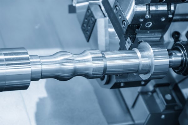
Preventing Bending Deformation in Slim Shafts
Shafts with length-to-diameter ratios exceeding 10 readily bend and chatter under radial cutting forces.
Elastic deflection causes middle-section enlargement, severe tool wear, and tip chipping.
- One-Clamp, One-Center with Follower Rests: Hydraulic tailstock centers apply controlled axial clamping force, while follower rests support the exact cutting point to counteract radial cutting forces.
- Reverse Turning Methods: Reversing feed direction—moving the tool from headstock toward tailstock—places the workpiece under tension rather than compression, eliminating force-induced bending.
- Stress Relief and Staged Processing: Stress-relief annealing after roughing, followed by straightening before final precision turning, removes residual internal stresses that distort concentricity.
Overcoming shaft deflection opens the door to controlling thin-walled component deformation.
Controlling Clamping Distortion in Thin-Walled Disks
Thin rings and disks deform under concentrated clamping forces from standard three-jaw chucks, springing back out-of-round upon release.
Spreading contact pressure and lowering clamping forces form the core logic for maintaining dimensional stability.
Full-circle pie jaws or wrapping collet chucks expand contact area, avoiding localized indentation from point contacts. Pneumatic or hydraulic systems lower clamping pressure to the minimum needed to prevent slippage without crushing the part. Multi-pass light cuts during finishing minimize heat and cutting resistance, eliminating roundness errors.
Standardizing these advanced techniques drives down production costs.
Strategies for Boosting Efficiency and Cutting Unit Costs
Once quality is locked in, program optimization and shop-floor automation shorten cycle times and increase profitability.
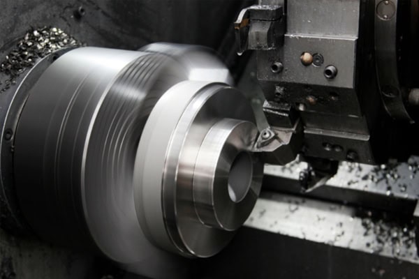
Toolpath Optimization and Non-Cutting Time Reduction
Detailed program code determines machine idle time.
Inefficient rapid positioning (G00) paths and overly cautious retract distances add hidden seconds to every cycle.
Refining approach and departure paths brings safe cutting entry points closer to workpiece contours. Using canned compound cycles (such as G76) for threading uses system algorithms to automatically reduce pass depth, cutting thread-cycle duration by over 20% compared to single-pass code (like G92). Setting tool-change points close to the clearance limit minimizes axial travel distances.
Complementing code tweaks with hardware-level automation delivers long-term productivity gains.
Mill-Turn Upgrades and Automated Material Handling
Consolidating processes and reducing manual touchpoints boost Overall Equipment Effectiveness (OEE) across modern machine shops.
Combining multiple operations onto a single machine eliminates queue time between departments and removes cumulative setup errors from re-clamping.
- Mill-Turn Multi-Tasking: CNC turning centers equipped with live tooling and C-axis control complete OD turning, face milling, cross-hole drilling, and tapping in a single setup.
- Bar Feeders and Gantry Robots: Automatic bar feeders or top-mounted gantry robots handle blank loading and finished part unloading, enabling untended 24/7 lights-out manufacturing.
- Zero-Point Quick-Change Systems: Worktable zero-point clamping plates allow off-machine fixture setup, dropping setup changeover times from hours to minutes.
Systematic process optimization and automation create a lean, highly competitive precision machining operation.
CNC turning is a comprehensive engineering discipline. Every detail—from machine rigidity maintenance and tool geometry to parameter tuning and deformation-free workholding—directly impacts final part precision and production cost. Applying flexible, tailored process techniques alongside modern automation empowers machine shops to deliver high pass rates, maximize throughput, and secure a strong cost advantage in competitive markets.
















