A liquid cold plate is a metal heat exchanger that removes heat from electronic components through circulating coolant. It uses internal channels or tubes to transfer heat away from CPUs, power modules, batteries, and other heat-generating devices. Compared with conventional air cooling, liquid cold plates can provide effective temperature control in compact systems with high thermal loads.
This guide explains how liquid cold plates work, their main types, materials, and applications. It also covers channel design, coolant selection, CNC machining, sealing methods, quality inspection, and factors affecting cooling performance.
What Is a Liquid Cold Plate?
A liquid cold plate is a compact heat exchanger that transfers heat from an electronic component into a circulating coolant. It typically consists of a metal plate containing internal channels or tubes, allowing liquid to carry heat away from the component and into a separate cooling system.
Liquid cold plates are commonly manufactured from aluminum or copper because these metals conduct heat effectively. The plate contacts a heat source through a mounting surface, often with a thermal interface material to reduce contact resistance. Coolant flowing inside the plate absorbs heat without normally contacting the electronic device directly.
The terms cold plate, liquid cooling plate, and liquid-cooled cold plate are often used interchangeably. However, a cold plate is only one component of a complete liquid cooling system. Its performance depends on the connected pump, coolant, heat exchanger, and operating conditions.
How Does a Liquid Cold Plate Work?
A liquid cold plate works by transferring heat from a component through a metal base and into a flowing coolant. The coolant absorbs the heat, leaves the cold plate, and carries thermal energy to an external heat exchanger before returning to repeat the cooling cycle.
This cold plate cooling process combines heat conduction, convection, and continuous fluid circulation. Understanding these stages helps engineers identify where thermal resistance occurs and how the complete system removes heat.
Heat Transfer and Coolant Flow
Heat first moves from the electronic component into the cold plate through conduction. The quality of the contact surface, thermal interface material, and base thickness influences this transfer. Poor contact can create a high-temperature region even when the coolant flow is sufficient.
As liquid moves through the internal channels, convection transfers heat from the metal walls into the coolant. Channel surface area, coolant temperature, flow conditions, and material conductivity all influence the heat transfer rate.
The coolant then exits at a higher temperature than it entered. For example, water carrying 500 W at approximately 2 L/min would experience a theoretical temperature rise of about 3.6°C, assuming steady single-phase operation and negligible external losses. Actual performance depends on the complete system.
Main Components of a Liquid Cold Plate
A liquid cold plate normally includes a base, internal fluid passages, inlet and outlet ports, and mounting features. Depending on its construction, it may also require a cover plate, tube inserts, seals, or permanently joined connections.
The base spreads heat from the electronic component toward the coolant passages. Internal channels determine where the coolant flows, while ports connect the plate to the cooling loop. Mounting holes help maintain the required contact pressure and alignment.
The most important components serve different functions:
| Component | Main Function | Important Design Consideration |
| Base Plate | Conducts and spreads heat | Thickness and thermal conductivity |
| Cooling Channels | Guide coolant through the plate | Geometry and flow distribution |
| Cover Plate | Encloses machined channels | Joint integrity and sealing |
| Inlet and Outlet Ports | Connect to the cooling loop | Flow capacity and connection design |
| Mounting Features | Secure the heat source | Flatness and contact pressure |
| Seals or Joined Interfaces | Prevent coolant leakage | Material compatibility and pressure resistance |
Not every design contains a separate cover plate. Embedded-tube constructions, for example, can form the wetted flow path with a continuous tube rather than a machined cavity sealed by a cover.
How a Complete Liquid Cooling Loop Works
A complete cold plate cooling system includes more than the plate itself. It generally combines a coolant pump, piping or hoses, fittings, a heat-rejection device, and the cold plate. Some systems also use reservoirs, manifolds, filters, or coolant distribution units.
The pump circulates coolant through the channels. Once the heated liquid leaves the cold plate, it reaches a radiator or another heat exchanger that releases the absorbed heat. The cooled liquid then returns to the inlet.
System performance depends on the interaction between these components. An effective cold plate may still operate poorly if the pump cannot overcome the required pressure drop or if several plates receive uneven flow. The cooling loop must therefore be evaluated as one system.
What Are the Main Types of Liquid Cold Plates?
The main types of liquid cold plates include embedded-tube, vacuum-brazed, friction stir welded, and microchannel designs. These constructions differ in how their flow passages are formed and sealed, affecting thermal performance, pressure resistance, manufacturing cost, and design flexibility.
Engineers choose a construction method according to the heat load, available space, coolant pressure, material, and expected production volume. Some terms describe a joining method, while others describe channel geometry, so the categories can overlap.
Embedded-Tube Cold Plates
Embedded-tube cold plates use metal tubes placed into grooves or formed passages in a conductive base. The tubing may be copper, stainless steel, or another compatible material, while the supporting plate is often aluminum.
CNC machining can form accurately positioned grooves that follow the heat-source layout. The tubes are inserted and secured using a suitable mechanical or bonding method. Good contact between the tube and base helps reduce resistance to heat transfer.
These designs are useful for moderate thermal loads and relatively simple flow paths. They can reduce manufacturing complexity, but tube placement limits channel flexibility. Insufficient tube-to-plate contact can also reduce cooling performance.
Vacuum-Brazed Cold Plates
Vacuum-brazed cold plates generally use CNC-machined channels enclosed by a cover plate. During brazing, a suitable filler metal joins the prepared surfaces inside a controlled vacuum environment, creating an enclosed fluid path.
The manufacturing sequence involves machining the flow passages, preparing the joining surfaces, assembling the parts, and performing the brazing operation. Complex channels can be positioned beneath concentrated heat sources, providing greater thermal design freedom.
The main challenges include joint preparation, filler-metal flow, dimensional changes during heating, and post-braze inspection. A brazed joint must be verified rather than assumed leak-tight. This construction is common where customized flow paths and compact packaging are required.
Friction Stir Welded Cold Plates
Friction stir welded cold plates use a solid-state joining process to close machined or formed cooling channels. A rotating tool generates frictional heat and mechanically stirs the material along the joint without melting the main workpieces.
Aluminum alloys are commonly used for this construction. CNC milling first produces the channels and joining features, while friction stir welding attaches the cover. The joint arrangement must allow sufficient tool access and support during welding.
Friction stir welding can provide strong joints with relatively low distortion when properly developed. However, weld parameters, material compatibility, tool access, and process validation remain important. This approach suits designs requiring durable joints and consistent production.
Microchannel Cold Plates
Microchannel cold plates contain many narrow passages positioned near the heat source. Their geometry increases coolant-contact surface area and can support high heat-flux removal in compact electronic devices.
Some microchannels are smaller than 1 mm, although the exact dimensions depend on the design. Narrower channels can improve local heat transfer but also increase flow resistance and sensitivity to blockage. Channel dimensions must therefore be selected together with pump capacity.
Precision CNC micromilling, specialized machining, and other manufacturing processes can produce suitable channel structures. Tool strength, burr formation, channel consistency, and cleanliness become increasingly important as the features become smaller.
| Cold Plate Type | Main Advantage | Main Limitation | Typical Application |
| Embedded-Tube | Relatively simple construction | Limited channel flexibility | Industrial electronics |
| Vacuum-Brazed | Flexible machined flow paths | Joining and inspection complexity | Custom electronics cooling |
| Friction Stir Welded | Strong solid-state joints | Specialized joining requirements | Automotive power modules |
| Microchannel | High heat-transfer area | Greater pressure drop and clogging sensitivity | High-power processors |
What Materials Are Used for Liquid Cold Plates?
Liquid cold plates are primarily manufactured from aluminum, copper, and stainless steel. Aluminum balances weight, machinability, and cost, copper provides higher thermal conductivity, and stainless steel offers strength and corrosion resistance for selected cooling environments.
Material selection depends on thermal conductivity, coolant compatibility, operating pressure, weight, and manufacturing requirements. A material with higher conductivity is not automatically the best option when the entire cooling system is considered.
Aluminum Cold Plates
An aluminum cold plate offers a useful balance of thermal conductivity, low weight, and machining efficiency. Aluminum alloys are widely used for customized plates because CNC milling can create channels, pockets, mounting holes, and sealing features.
For example, 6061 aluminum has a typical room-temperature thermal conductivity of approximately 167 W/(m·K), depending on temper and condition. Its relatively low density makes it attractive for automotive, electronics, and weight-sensitive equipment.
Aluminum designs still require corrosion management. Coolant chemistry, joining processes, and compatibility with other wetted metals must be considered. Surface treatments may also affect sealing dimensions or thermal interfaces and should be specified accordingly.
Copper Cold Plates
Copper cold plates provide higher thermal conductivity than commonly used aluminum alloys. Copper can transfer heat efficiently from concentrated electronic heat sources into nearby cooling channels, making it useful for demanding thermal designs.
Common high-conductivity copper grades can approach approximately 390 W/(m·K) at room temperature. However, copper is considerably denser than aluminum and usually costs more. Its greater weight can become important in large or weight-sensitive assemblies.
Copper machining also requires suitable cutting conditions to control burrs, tool adhesion, and surface quality. The manufacturing process should account for the selected copper grade, final dimensions, and any required joining or protective treatment.
Stainless Steel Cold Plates
Stainless steel cold plates are used when mechanical strength, chemical compatibility, or corrosion behavior is more important than maximum thermal conductivity. They may be appropriate for certain industrial, laboratory, and specialized fluid systems.
For comparison, 304 stainless steel has a typical thermal conductivity of approximately 16 W/(m·K), substantially below aluminum or copper. This creates greater conduction resistance for a similar plate geometry, which must be considered during thermal design.
Stainless steel can also increase machining time because of its cutting behavior and work-hardening tendency. Where stainless steel is required, engineers may compensate through shorter thermal paths, suitable wall thicknesses, or different flow geometries.
| Material | Typical Thermal Conductivity | Main Advantage | Main Trade-Off |
| Aluminum 6061 | ~167 W/(m·K) | Lightweight and machinable | Lower conductivity than copper |
| High-Conductivity Copper | ~390 W/(m·K) | Excellent heat conduction | Higher weight and cost |
| Stainless Steel 304 | ~16 W/(m·K) | Strength and corrosion resistance | Higher thermal resistance |
Values are approximate room-temperature material examples, not universal specifications for every alloy or condition.
What Affects Liquid Cold Plate Cooling Performance?
Liquid cold plate cooling performance depends on channel geometry, coolant flow rate, pressure drop, thermal contact, material conductivity, and coolant properties. Effective design balances heat removal with pumping energy, temperature uniformity, mechanical strength, and long-term reliability.
These factors interact rather than acting independently. Increasing coolant flow or channel surface area may improve heat transfer, but can also increase pressure loss, manufacturing difficulty, or system cost.
Channel Geometry and Heat Transfer Efficiency
Channel geometry determines how coolant travels beneath heat-generating components. Width, depth, spacing, number of passages, and the arrangement of inlet and outlet manifolds all influence heat distribution and local flow conditions.
A dense channel pattern provides more wetted surface area, but smaller passages usually increase hydraulic resistance. Sharp turns, poorly balanced branches, and dead zones can produce uneven cooling or unnecessary pressure losses.
Engineers can compare designs using thermal resistance, commonly expressed in K/W. For example, an illustrative 500 W load with a source-to-inlet thermal resistance of 0.08 K/W produces a 40°C temperature difference. The reference temperatures must be clearly defined when comparing results.
Coolant Flow Rate and Pressure Drop
Coolant flow rate affects how quickly thermal energy leaves a cold plate. For a single-phase liquid, the heat carried is approximately proportional to mass flow rate, specific heat capacity, and the temperature rise between inlet and outlet.
Pressure drop represents the resistance the flowing coolant experiences across the plate. Narrow channels, longer paths, and restrictive fittings can increase this resistance. A pump must provide the required flow at the actual system pressure loss.
Higher flow is not automatically the most efficient choice. Beyond a certain point, additional pumping power may produce only modest thermal improvement. Engineers should evaluate measured or predicted flow-versus-pressure curves alongside the required temperature limits.
Thermal Contact and Mounting Design
Thermal contact determines how effectively heat enters the cold plate. Surface flatness, roughness, mounting pressure, and the thickness of thermal interface material all affect the resistance between the electronic component and the cooling plate.
A flat, accurately machined mounting surface provides a stable foundation for heat transfer. However, even polished metal surfaces contain microscopic irregularities. A suitable thermal interface material helps fill these gaps and reduce trapped air.
Mounting hardware must distribute pressure without damaging the component or bending the plate excessively. Screw locations, tightening sequence, stiffness, and thermal expansion can influence contact uniformity. These mechanical details are especially important for large or delicate electronic assemblies.
Coolant Selection, Corrosion, and Cleanliness
Coolant selection affects heat capacity, viscosity, freezing protection, corrosion behavior, and compatibility with seals. Water-based coolants generally provide effective heat transfer, while glycol mixtures can offer additional freezing protection.
Mixed-metal cooling loops require careful corrosion management. For example, electrically connected aluminum and copper exposed to a conductive coolant may create galvanic corrosion conditions. Compatible materials, qualified inhibitors, and appropriate water chemistry help manage this risk.
Cleanliness is equally important, particularly for microchannels. Machining chips, oxide particles, and deposits can restrict flow or create local hot spots. Suitable cleaning, filtration, and fluid maintenance must therefore be part of the complete cooling-system design.
How Are Liquid Cold Plates CNC Machined?
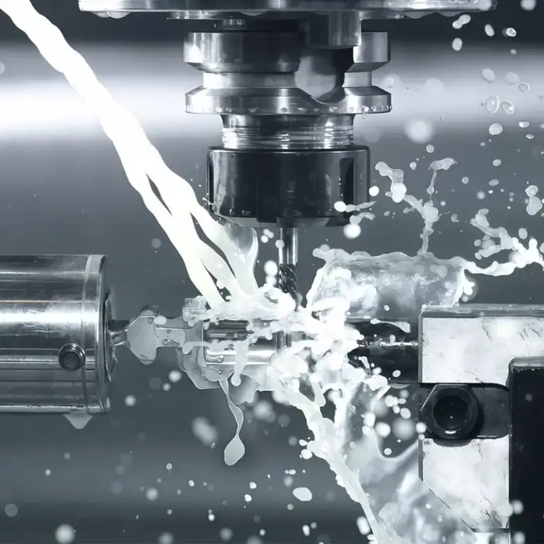
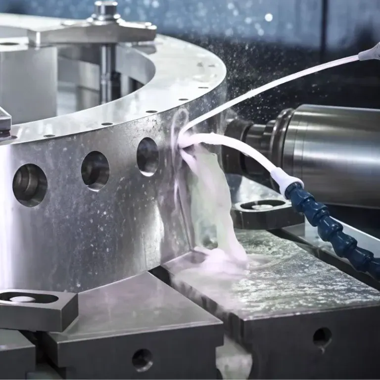
Liquid cold plates are CNC machined by milling cooling channels, creating mounting and sealing features, and finishing critical contact surfaces. Depending on the design, the machined components are then joined, cleaned, leak-tested, and inspected to confirm their dimensional and thermal requirements.

CNC machining is particularly important for custom cold plates with complex flow paths, precise mounting interfaces, or limited installation space. The process must account for both mechanical accuracy and the final cooling function.
CNC Milling of Cooling Channels and Internal Features
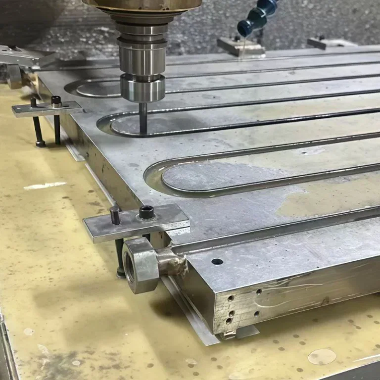
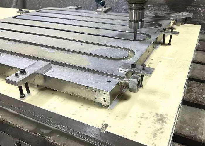
CNC milling produces cooling channels, manifolds, grooves, and pockets inside a metal plate. The process allows engineers to position coolant passages beneath heat sources while maintaining the specified wall thickness and channel geometry.
Tool selection depends on channel width, depth, corner geometry, and material. Small-diameter tools can machine narrow passages but may be more sensitive to deflection, wear, and breakage. Roughing and finishing strategies should preserve channel consistency.
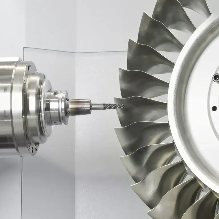
Multi-axis CNC machining can also help produce complex external surfaces, angled ports, and mounting features. However, very small internal channels may require specialized methods. Manufacturing feasibility should be reviewed before finalizing an intricate cooling design.
Precision Machining of Sealing Surfaces and Mounting Features
Sealing surfaces and mounting features require accurate machining because they determine whether the cold plate can be assembled securely and operate without leakage. Flatness, groove dimensions, hole positions, and surface quality must follow the specified design.
An O-ring groove requires suitable width, depth, and surface condition for the selected seal. Similarly, threaded ports must provide adequate engagement and compatibility with the intended fittings. The required tolerances depend on operating pressure and joint design.
Engineers should control several critical features:
- Contact-surface flatness for consistent thermal interface pressure.
- Channel wall thickness for strength and heat-transfer performance.
- O-ring groove geometry for controlled seal compression.
- Port and thread dimensions for reliable fluid connections.
- Mounting-hole locations for accurate equipment assembly.
These features should be inspected using appropriate measuring equipment before final assembly or subsequent joining operations.
Joining, Sealing, and Leak Testing
Joining closes the internal coolant passages and creates a pressure-containing assembly. Depending on the design, manufacturers may use vacuum brazing, friction stir welding, bonded tubes, or mechanically sealed covers.
Each joining process introduces different manufacturing risks. Brazing requires control of filler material and thermal exposure, while friction stir welding depends on tool access and process parameters. The chosen method must be compatible with the plate material and operating requirements.
After joining, completed cold plates generally require a defined leak or pressure test. Suitable methods may include pressure-decay testing, helium leak testing, or hydrostatic testing. Test pressure, duration, allowable leakage, and safety procedures must follow the engineering specification, no single value suits every design.
Dimensional Inspection and Thermal Performance Testing
Dimensional inspection verifies the geometry of the machined cold plate. Important characteristics may include contact-surface flatness, mounting-hole location, port dimensions, wall thickness, and alignment between joined components.
Depending on the design, coordinate measuring machines, precision gauges, and surface-measuring equipment can verify these requirements. For high-accuracy parts, inspection should take place under appropriate temperature conditions to minimize measurement errors caused by thermal expansion.
Thermal performance testing evaluates the assembled plate under defined operating conditions. Engineers typically monitor heat input, coolant inlet and outlet temperatures, flow rate, pressure drop, and component temperature. Comparing these measurements with the design targets helps confirm whether the manufactured cooling solution performs as intended.
Where Are Liquid Cold Plates Used?
Liquid cold plates are used in data centers, power electronics, battery systems, aerospace equipment, medical devices, and industrial machinery. They are particularly valuable where concentrated heat loads, compact packaging, or strict temperature requirements make conventional air cooling difficult.
The cooling requirements vary by application. Some systems prioritize maximum heat removal, while others require temperature stability, low weight, limited vibration, or reliable operation under changing loads.
Data Centers and High-Performance Computing
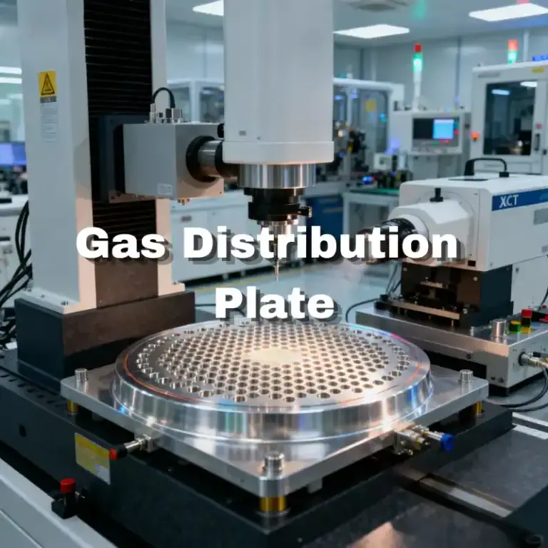
Data centers use liquid cold plates to remove heat from processors, graphics accelerators, and other high-power computing components. Direct-to-chip cooling places the cold plate close to the primary heat source to support efficient thermal transfer.
High-performance computing systems often contain several powerful devices in limited space. Managing coolant distribution across multiple plates is therefore important. Uneven flow can cause individual components to operate at higher temperatures.
Manufacturing requirements may include closely spaced channels, precise mounting patterns, and carefully controlled contact surfaces. Reliable sealing and cleanliness are also essential because coolant leakage or channel blockage can interrupt expensive computing equipment.
Power Electronics, Batteries, and Renewable Energy
Liquid cold plates help control temperature in power converters, inverters, battery assemblies, and charging equipment. Components such as IGBT and SiC power modules can generate substantial heat during electrical operation.
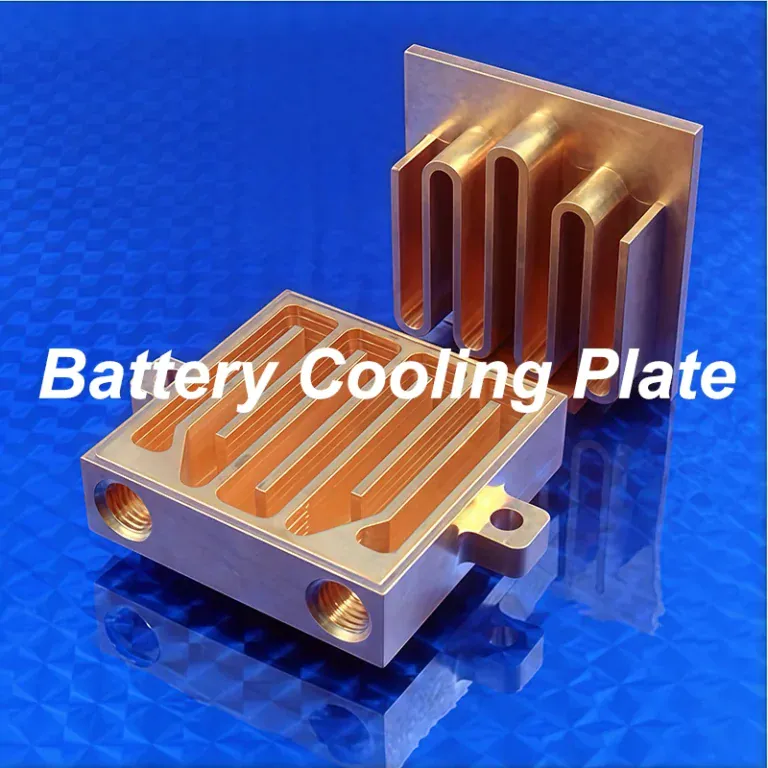
In battery systems, the objective may be to limit maximum temperature and reduce temperature differences between cells or modules. In power electronics, localized hot spots and thermal cycling can be important considerations for component reliability.
Aluminum cold plates are frequently considered for these applications because of their weight and manufacturing advantages. The final channel arrangement must reflect the position of the heat sources, expected operating loads, and available coolant circulation.
Aerospace and Defense Systems
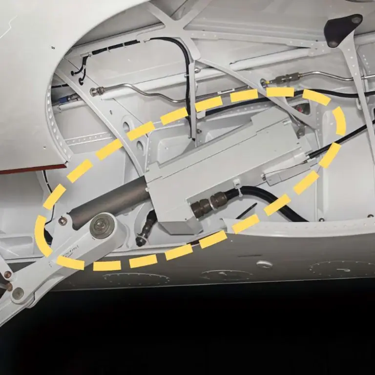
Aerospace and defense equipment uses liquid cold plates to manage heat in selected avionics, radar, RF electronics, power conversion systems, and spacecraft payloads. These applications often combine high power density with strict space and weight constraints.
In radar and electronic warfare equipment, temperature stability can influence electronic performance. Mechanical design must also account for vibration, pressure conditions, environmental exposure, and the requirements of the specific program.
Precision-machined interfaces, compatible materials, and controlled fluid passages support these designs. However, aerospace applications may require additional qualification, traceability, and testing beyond standard industrial manufacturing.
Medical and Industrial Equipment
Medical and industrial equipment uses liquid cold plates when consistent cooling is necessary for reliable operation. Typical applications include laboratory instruments, laser systems, imaging equipment, and industrial power supplies.
A laser system may require stable component temperatures to control optical performance, while industrial equipment may need to remove continuous heat without large external cooling structures. The required design depends on temperature sensitivity and environmental conditions.
Customized mounting surfaces, channel arrangements, and port locations can help integrate a cold plate into existing equipment. Engineers should also consider service access, fluid compatibility, cleaning requirements, and expected maintenance intervals.
What Are the Advantages and Limitations of Liquid Cold Plates?
Liquid cold plates offer high heat-removal capability, compact integration, and flexible thermal design. Their main limitations are increased system complexity, leakage risk, coolant maintenance, and potentially higher cost compared with simple air-cooled heat sinks.

The advantages depend on the application rather than the cooling technology alone. Liquid cooling becomes attractive when the thermal benefits justify the additional mechanical and fluid-handling requirements.
Advantages of Liquid Cold Plate Cooling
Liquid cold plates can remove concentrated heat from compact electronic packages. They transport thermal energy away from the heat source to a separate heat-rejection device, allowing cooling hardware to be arranged more flexibly.
Custom channels also allow engineers to concentrate cooling beneath the hottest areas. This can improve temperature uniformity and reduce reliance on large local airflow paths, particularly in densely packaged equipment.
Their main benefits include:
- Effective heat removal for concentrated thermal loads.
- Compact cooling interfaces near electronic components.
- Flexible channel and mounting configurations.
- Potentially improved temperature uniformity.
- Separation of heat collection and final heat rejection.
Actual benefits must be confirmed against the complete system, including pumps, external heat exchangers, and operating conditions.
Limitations and Maintenance Requirements
Liquid cold plate systems require additional components such as pumps, hoses, fittings, and heat exchangers. These increase installation complexity and introduce possible failure points that are not present in a simple passive heat sink.
Coolant leaks, corrosion, blocked channels, and pump problems can reduce cooling performance or damage surrounding equipment. Narrow channels are especially sensitive to particles and deposits, making cleanliness and filtration important.
Maintenance planning should consider fluid condition, connector integrity, filter replacement, and performance monitoring. The required interval depends on the coolant and operating environment. A well-designed system must remain practical to inspect and service throughout its intended life.
Liquid Cold Plates vs. Air Cooling and Immersion Cooling
Liquid cold plates, air cooling, and immersion cooling remove heat through different system architectures. Air cooling transfers heat to moving air through a heat sink, while cold plates collect heat directly into a liquid loop.
Immersion cooling places compatible electronic assemblies in a dielectric fluid. It can cool a larger portion of the assembly, whereas cold plates target selected components through dedicated mechanical interfaces.
| Cooling Method | Main Advantage | Main Limitation | Suitable Use |
| Air Cooling | Simple and widely available | Requires airflow and heat-sink space | Low to moderate thermal loads |
| Liquid Cold Plate | Targeted, compact heat collection | Requires a sealed liquid loop | High-power chips and modules |
| Immersion Cooling | Broad component exposure to coolant | Fluid compatibility and service complexity | Dense electronic assemblies |
The best choice depends on heat distribution, electrical packaging, maintenance requirements, infrastructure, and total system cost.
How Do You Choose the Right Liquid Cold Plate?
The right liquid cold plate is selected by matching heat load, allowable temperature, coolant flow, pressure drop, material, mounting space, and manufacturing requirements. Engineers must also decide whether a standard design is sufficient or a custom plate is needed.
Selection should begin with the thermal and mechanical requirements rather than the lowest initial price. The chosen design must provide the required cooling performance while remaining practical to manufacture, integrate, and maintain.
Standard vs. Custom Cold Plates
Standard cold plates are available with predetermined dimensions, mounting layouts, and flow passages. They can be suitable when the equipment has compatible installation space and the thermal requirements fall within the product’s operating range.
Custom cold plates are designed around specific heat-source locations, available geometry, and coolant connections. CNC machining makes it possible to adjust channel patterns, mounting holes, sealing interfaces, and external shapes for a particular assembly.
Customization creates additional engineering and manufacturing work, but may improve integration or cooling distribution. The decision should compare the total system benefit against development time, tooling, process validation, and expected production quantity.
Cost, Lead Time, and Manufacturing Considerations
Cold plate manufacturing cost depends on material, geometry, machining time, joining method, tolerances, and testing requirements. Copper material and very fine channels may increase cost, while simple aluminum designs can often be machined more efficiently.
Lead time also depends on the number of manufacturing stages. A machined plate requiring subsequent vacuum brazing, cleaning, leak testing, and thermal validation can involve more coordination than a basic machined component.
Engineers can improve manufacturing efficiency by simplifying unnecessary features, using practical corner radii, maintaining accessible tool paths, and assigning tight tolerances only where needed. Design for manufacturability should not compromise thermal performance or sealing integrity.
Choosing a Liquid Cold Plate Manufacturer
A suitable cold plate manufacturer should understand both thermal requirements and mechanical manufacturing constraints. CNC machining capability is especially important for customized channels, precise sealing features, and difficult mounting geometries.
Buyers should evaluate manufacturing equipment, inspection methods, material handling, and how joining and validation processes are controlled. A supplier that machines individual components may work with other qualified providers for brazing, welding, or complete system testing.
The best supplier arrangement is one that clearly assigns responsibility for each process and acceptance requirement. For custom cold plates, early technical communication helps identify machining limitations, assembly concerns, and potential cost increases before production.
FAQs
What Are Cold Plates?
Cold plates are heat-transfer devices that collect thermal energy from a component through a solid contact surface. In electronics, the term usually refers to a liquid-cooled plate with internal fluid passages. However, it can also describe temperature-controlled plates used in laboratories or other equipment. The important distinction is the cooling mechanism. A liquid cold plate removes heat through circulating coolant, whereas a thermoelectric plate uses an electrically powered temperature-control device. These products may look similar but have different operating requirements.
How Do Liquid Cold Plates Work During Startup?
During startup, a liquid cold plate begins removing heat as coolant flow and the temperature difference between the component and coolant develop. Its final operating temperature is not reached immediately because the metal, coolant, and connected equipment have thermal mass. For example, a 300 W heat load at 1 L/min of water produces an ideal steady-state coolant temperature rise of about 4.3°C. Actual startup behavior depends on pump operation, initial temperatures, thermal resistance, and the control system.
Can Liquid Cold Plates Cool Below Ambient Temperature?
Yes, a liquid cold plate can maintain a surface below ambient temperature if the supplied coolant is sufficiently cold and the cooling system has adequate capacity. However, below-ambient operation creates a condensation risk. If the plate surface falls below the surrounding air’s dew point, moisture can form on exposed surfaces. Engineers may need insulation, vapor barriers, humidity control, and suitable seals. The design must consider both thermal performance and electrical safety, especially when the cold plate is installed near sensitive electronics.
What Happens If Coolant Flow Stops in a Cold Plate?
If coolant flow stops, the cold plate can no longer transport heat away effectively through circulation. Its metal mass may absorb heat temporarily, but the component temperature will generally rise while heat generation continues. The rate depends on thermal load, stored thermal energy, and remaining heat-loss paths. Critical systems may use flow sensors, temperature monitoring, alarms, or automatic power reduction to respond to this condition. Protection thresholds should be determined through the equipment’s thermal design and validation process.
Conclusion
A liquid cold plate removes heat through a combination of metal conduction and circulating coolant, making it useful for compact systems with demanding thermal requirements. Choosing the right design requires balancing material conductivity, internal channels, coolant flow, pressure drop, sealing, and manufacturing cost. CNC machining plays an important role in producing accurate channels, mounting features, and contact surfaces. Reliable cooling also depends on suitable joining methods, dimensional inspection, leak testing, and validation under actual operating conditions.
At TiRapid, we provide precision CNC machining and manufacturing services for custom aluminum and copper components. Our CNC milling, turning, multi-axis machining, DFM support, and dimensional inspection help customers manufacture accurate cooling channels, sealing features, mounting interfaces, and other precision parts for demanding thermal management applications.