A battery cooling plate helps transfer heat between battery cells and a cooling system. In many electric vehicles, liquid flows through channels inside the plate, carrying heat away from the battery pack during charging and operation. Some systems can also circulate warm coolant to help raise battery temperature in cold conditions.
Choosing a cooling plate involves more than selecting a conductive material. Engineers must consider the battery layout, thermal contact, coolant flow, pressure drop, sealing, and manufacturing method. This guide explains how battery cooling plates work, compares common constructions, and outlines the information buyers should prepare when sourcing a custom plate.
What Is a Battery Cooling Plate?
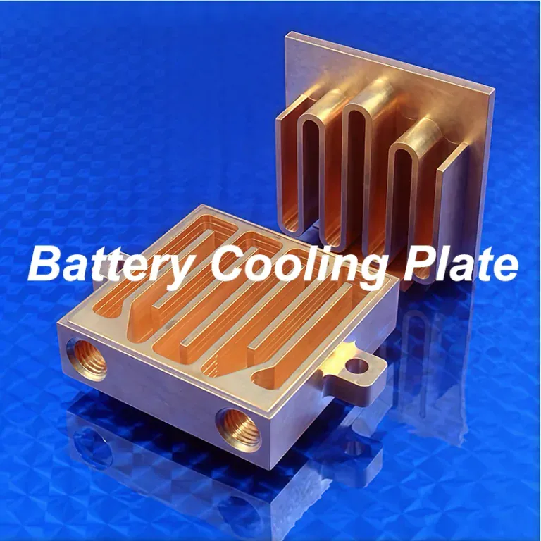
A battery cooling plate is a component that transfers heat between a battery and a cooling system. In a liquid-cooled design, the plate provides a heat-transfer path from the cells or module to coolant flowing through enclosed passages.
The Role of a Cooling Plate in an EV Battery Pack
Battery cells generate heat during charging and discharging. If heat is not managed effectively, cell temperatures can rise or become uneven across the pack.
A cooling plate provides a controlled path for heat to leave the cells or module. It is positioned to contact selected battery surfaces, either directly or through a thermal interface material. The plate then transfers heat to a circulating coolant.
The cooling plate is part of a larger battery thermal management system. Its effectiveness also depends on the cell layout, contact conditions, coolant flow, control strategy, and the system’s ability to remove heat from the coolant.
Battery Cooling Plate and Battery Cold Plate Terminology
The terms battery cooling plate and battery cold plate are often used to describe a liquid-cooled plate that helps regulate battery temperature. Suppliers may also use terms such as battery liquid cooling plate or battery liquid cold plate.
The name alone does not define the construction. One plate may contain machined channels sealed by a cover, while another may use formed sheets or tubes. When comparing products, review the drawings and specifications for the coolant path, material, interfaces, and intended application.
Main Components of a Liquid Cooling Plate Assembly
A liquid cooling plate assembly generally includes a heat-transfer surface, coolant passages, and connections for coolant entry and exit. Depending on the construction, it may also include a cover plate, tubes, headers, fittings, seals, or mounting features.
The plate may be supplied as a separate component or integrated into a larger battery tray or enclosure. The complete battery system can also include pumps, hoses, valves, sensors, a heat exchanger, and temperature controls. These components work together, but they are not necessarily part of the cooling plate itself.
How Does a Battery Cooling Plate Work?
A battery cooling plate transfers heat from the cells or module through a contact interface and plate material to a circulating coolant. The coolant then carries the heat to another part of the thermal management system.
Heat Transfer From the Cells to the Plate
During operation, heat generated inside a cell moves toward its outer surfaces. It then passes into the cooling plate through the available contact area.
The quality of this contact affects the heat path. Small surface variations or assembly gaps can leave air between the battery and the plate. Thermal interface materials, such as pads or gap fillers, may be used to improve contact across those gaps.
The interface material must also suit the assembly. Its thickness, compressibility, thermal properties, electrical requirements, and compatibility with adjacent materials should be considered together.
How Coolant Carries Heat Through the Channels
Coolant enters the plate through an inlet, flows through internal passages, and leaves through an outlet. As it moves, it receives heat from the channel walls and carries that heat away.
Channel shape, length, cross-section, and layout affect both heat transfer and resistance to flow. Increasing coolant flow may improve heat transfer in some conditions, but it can also increase pressure drop and pumping demand.
The aim is to provide the required thermal performance across the battery pack while remaining within the cooling system’s flow and pressure limits.
How the Cooling Plate Connects to the Thermal Management System
The plate works with a coolant loop rather than operating as a complete cooling system on its own. A pump circulates coolant through the passages, while hoses or manifolds connect the plate to other components.
After leaving the plate, the coolant passes through a heat exchanger or another system component that removes heat from the loop. Sensors and controls help regulate operation according to the battery’s needs.
The exact arrangement varies by vehicle and battery design. Some systems use additional components, such as a chiller, heater, or heat pump.
Can a Cooling Plate Also Help Warm a Battery?
Yes. In some systems, warm coolant can flow through the same plate to transfer heat toward the battery in cold conditions. The heat may come from a heater, heat pump, or another suitable source in the vehicle’s thermal management system.
The plate itself does not determine whether heating is available. That function depends on the complete coolant circuit and its controls.
What Are the Common Types of Battery Cooling Plates?
Battery cooling plates use several constructions, including stamped and brazed, extruded, machined and joined, and tube-in-plate designs. The choice depends on thermal requirements, available space, production quantity, and the desired coolant path.

Stamped and Brazed Cooling Plates
Stamped cooling plates are made by forming channel features in metal sheets. The formed sheets are then joined, often by brazing, to create enclosed coolant passages.
This construction can provide broad contact surfaces and relatively thin plate designs. It can be suitable for larger production quantities, although tooling, joining requirements, and the selected channel geometry affect the overall cost.
The design must account for the quality of the joint, the required sealing performance, and any dimensional changes caused by the joining process.
Extruded Cooling Plates
Extrusion forms a continuous metal profile with passages running along its length. The profile is cut and combined with the necessary end connections or headers to direct coolant through the plate.
Extruded constructions can be useful when a design benefits from long, relatively consistent channels. The available passage geometry is influenced by the extrusion process, so some flow paths may require additional machining or separate components.
Machined and Joined Cooling Plates
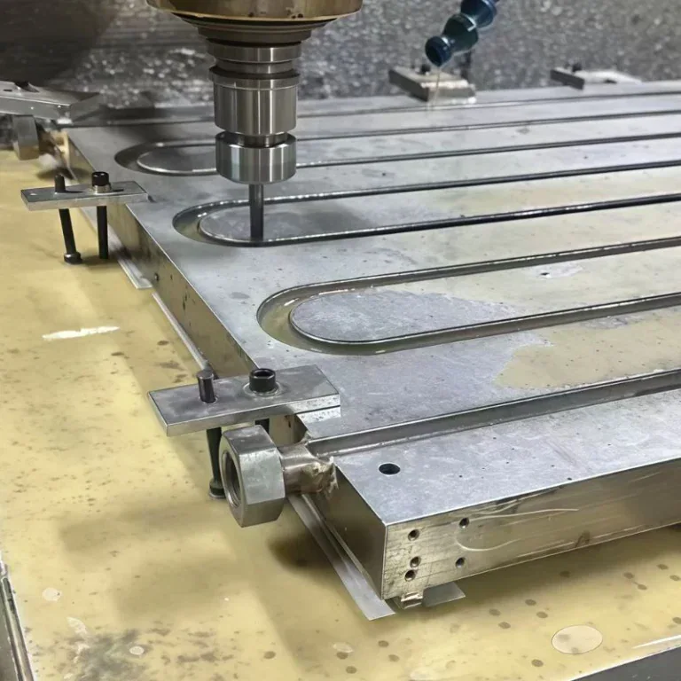
A machined cooling plate typically starts with a metal blank. CNC machining removes material to create open channels, ports, mounting features, and other details. A cover or mating component is then joined to enclose the coolant path.
This approach allows channels and interfaces to be tailored to a particular design. It can be useful for prototypes, development projects, and geometries that require machined features. The final route still depends on the plate size, material, tolerances, joining method, and production quantity.
Tube-in-Plate Cooling Plates
A tube-in-plate design uses tubes to carry coolant through or along a plate structure. The plate provides a heat-transfer surface between the battery and the coolant in the tubes.
Tube placement, contact between the tube and plate, and the joining or retention method all affect performance. The design also needs to accommodate tube connections and the intended battery layout.
How Cell Format and Pack Layout Affect the Choice
Battery cells may be cylindrical, prismatic, or pouch-shaped. Each format presents different surfaces and packaging constraints for thermal contact.
For example, a flat plate may contact the bottom or side of a module, while another arrangement may place cooling passages between cell rows. The cell format alone does not determine the best solution. Heat load, available contact area, structural requirements, and service conditions must also be considered.
What Materials Are Used for Battery Cooling Plates?
Aluminum alloys are widely used for battery cooling plates because they offer useful thermal conductivity at relatively low weight. Copper and other materials may be selected when the thermal, mechanical, or chemical requirements justify them.
Aluminum and Aluminum Alloys
Aluminum alloys are common in battery thermal management because they combine heat-transfer capability with relatively low mass. They can also be formed, extruded, machined, and joined using a range of manufacturing methods.
Different alloys and material conditions have different strengths, corrosion behavior, and manufacturing characteristics. The selected grade must be compatible with the intended construction and joining process.
For a machined plate, the material choice should also account for the required wall thickness, contact surface, ports, and dimensional stability.
Copper and Other Materials
Copper has high thermal conductivity and may be considered where heat must spread through a restricted area or where the thermal design calls for it. Its higher weight and material cost can influence the decision.
Other materials may be used for fittings, tubes, seals, or specific plate constructions. The best choice depends on the complete assembly rather than a single material property. A highly conductive plate will not deliver its intended performance if contact, flow distribution, or system integration is inadequate.
Coolant Compatibility and Corrosion Considerations
Material selection must consider both the coolant and the other materials in the loop. Coolant chemistry, operating temperature, fluid additives, and service conditions can affect corrosion behavior.
When different metals are connected in a coolant system, galvanic corrosion may also need to be evaluated. The coolant supplier’s and equipment manufacturer’s specifications should be reviewed alongside the plate material and fitting selections.
Surface treatments or coatings may be specified for particular applications, but they must be compatible with the required thermal contact, coolant exposure, and assembly conditions.
What Should Engineers Consider in Battery Cooling Plate Design?
A battery cooling plate must provide an effective heat path while meeting flow, pressure, sealing, structural, and packaging requirements. These factors interact, so the design should be evaluated as part of the complete battery system.
Heat Load and Cell Temperature Uniformity
The cooling plate should be designed around the heat generated by the battery under its intended operating conditions. Charging, discharging, ambient temperature, and duty cycle can all influence the thermal load.
Engineers also need to consider temperature differences across the pack. If coolant warms as it moves through a long flow path, cells near the outlet may experience different cooling conditions from those near the inlet.
The required temperature limits and acceptable variation should come from the cell and battery system specifications. They should not be assumed from a general value used for a different battery design.
Flow Path, Coolant Distribution, and Pressure Drop
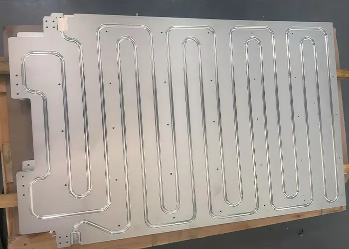
Common flow paths include serpentine and parallel arrangements. A serpentine path directs coolant through a continuous route, while parallel paths divide flow among multiple passages.
Each arrangement presents trade-offs. A longer path can increase coolant temperature rise and flow resistance. Parallel passages may reduce the length of individual paths, but they require attention to how evenly coolant is distributed.
Channel size, flow rate, coolant properties, and the available pump capacity should be considered together. A design that improves heat transfer at the plate level may not be suitable if it exceeds the system’s pressure limits.
Contact Area, Flatness, and Thermal Interface Materials
Heat must cross the interface between the battery and the plate before it reaches the coolant. Effective contact depends on the shape and condition of both surfaces, assembly pressure, and any thermal interface material used.
Flatness and surface condition should be specified according to the actual contact arrangement. A gap filler may accommodate some surface variation, but its thickness and compression also influence thermal resistance.
The plate and interface material should therefore be evaluated together. Improving the channel design alone may not resolve a poor contact condition at the battery surface.
Mechanical Strength, Sealing, and Pack Integration
A cooling plate may need to withstand coolant pressure, installation loads, vibration, and thermal cycling. Some designs also form part of a battery tray or support structure.
Wall thickness and joint design must satisfy the required loads while leaving room for the coolant path and battery components. Ports, fittings, fasteners, and sealing features must fit the available packaging space.
The required electrical isolation and the consequences of coolant leakage should also be considered at the battery system level. These requirements depend on the pack architecture and applicable specifications.
How Are Battery Cooling Plates Manufactured?
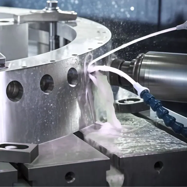
Battery cooling plates can be formed, extruded, machined, and joined using different process combinations. CNC machining is particularly useful for creating precise channels, ports, mounting features, and contact surfaces where the design requires them.
Forming and Machining the Plate Features
Manufacturing may begin with sheet, plate, an extrusion, or another suitable blank. Stamping and forming can create channel features in sheet-based designs, while extrusion can produce continuous passages in a profile.
Machining may be used to complete features that require tighter dimensional control or cannot be formed directly. These can include mounting holes, locating features, sealing areas, and interfaces for coolant fittings.
The chosen route depends on geometry, material, tooling investment, and expected quantity. A process suitable for a prototype is not automatically the most economical route for a high-volume design.
CNC Machining for Channels, Ports, and Interfaces
CNC milling can create open coolant channels in a plate before a cover is attached. It can also machine pockets, flat contact surfaces, port features, threads, and mounting holes.
For large or thin plates, workholding and machining sequence are important because clamping forces and material removal can affect flatness. Deep or narrow channels may also require careful tool selection and chip removal.
The design should identify which surfaces are critical for thermal contact, sealing, or assembly. This allows the manufacturer to plan machining and inspection around the features that matter most.
Joining Methods for Enclosed Coolant Passages
After channels are formed or machined, they may need to be enclosed by joining a cover or another plate. Depending on the material and design, methods can include brazing, friction stir welding, or other suitable welding processes.
The joint must meet the specified sealing and mechanical requirements. It can also affect flatness or other dimensions, so the process plan may include inspection or finish machining after joining.
Joining method selection should consider the coolant path, material compatibility, allowable distortion, access, and production volume.
Surface Treatment, Cleaning, and Assembly
Surface treatment may be specified to address corrosion, electrical, or other functional requirements. Treated areas and any masking requirements should be clearly identified, especially around contact surfaces, seals, and ports.
Internal cleaning is important because machining chips, joining residues, or other particles can remain in coolant passages. The cleaning method must reach the relevant areas without damaging the finished assembly.
Fittings, seals, and protective caps are installed according to the agreed supply scope. Cleanliness and handling requirements should be maintained through packaging and delivery.
How Is Battery Cooling Plate Quality Verified?
Quality verification can include dimensional inspection, leak and pressure testing, flow testing, and thermal evaluation. The required checks and acceptance limits depend on the component design and the customer’s specifications.
Dimensional Accuracy and Contact Surface Inspection
Dimensional inspection confirms that the plate matches the drawing and can be installed in the battery assembly. Important features may include overall dimensions, mounting holes, port locations, plate thickness, and the position of sealing interfaces.
The contact surface may require flatness or surface condition checks. The inspection method and support conditions should be agreed on, particularly for large or thin plates that can deflect under their own weight or during measurement.
Leak and Pressure Testing
Leak testing checks whether coolant can escape from the enclosed passages or connections under the specified test conditions. Pressure testing may also be required to verify the assembly against a defined pressure condition.
The test medium, pressure, duration, fixtures, and acceptance criteria should be specified before production. A pressure value used for one design should not be assumed suitable for another.
A plate that passes a leak test has demonstrated the specified sealing condition under that test. The result does not by itself establish the plate’s thermal performance or the complete battery pack’s safety.
Coolant Flow and Thermal Performance Testing
Flow testing can help confirm that the coolant path provides the expected flow and pressure characteristics. It may also identify a blockage or an unintended restriction.
Thermal testing evaluates how the plate performs under defined heat load, coolant inlet conditions, flow rate, and contact conditions. The test should reflect the intended application as closely as the project requires.
Results from different tests are only directly comparable when their operating conditions and measurement methods are understood.
Cleanliness and Documentation
Cleanliness verification may be required to confirm that particles or residues remaining inside the coolant path meet the agreed acceptance criteria.
Depending on the project, documentation may include material records, dimensional inspection results, leak test reports, and other required test data. Buyers should identify these deliverables during the quotation stage so suppliers can include the relevant processes and reporting.
What Should Buyers Provide When Requesting a Quote?
A clear quotation package should define the plate geometry, materials, coolant interfaces, operating conditions, quantity, and acceptance requirements. This helps suppliers assess manufacturability and quote the same scope of work.
Drawings, Materials, and Production Quantity
Provide the current engineering drawing and CAD model when available. The documents should identify overall dimensions, channel geometry, port locations, mounting features, critical tolerances, and contact surfaces.
Specify the material grade and condition, along with prototype and production quantities. If the design is still under development, identify which features are fixed and which can be reviewed for manufacturability.
Thermal and Coolant Requirements
Share the relevant thermal load, coolant type, inlet conditions, target flow rate, and allowable pressure drop when these are part of the supplier’s assessment. Also identify the battery contact area and any thermal interface material requirements.
If the thermal design is already complete, provide the controlling specifications rather than assuming the machining supplier is responsible for system-level thermal design.
Joining, Testing, and Acceptance Requirements
State whether the supplier is expected to provide a machined base plate, a joined cooling plate, or a complete assembly with fittings and seals. Identify the required joining method if it is already defined.
Include any requirements for leak testing, pressure testing, cleanliness, inspection reports, and packaging. Clear acceptance criteria allow the supplier to evaluate the work and help buyers compare quotations on the same basis.
FAQs
What Is the Difference Between a Battery Cooling Plate and a Cold Plate?
A battery cooling plate is a type of cold plate designed to manage battery temperature. The broader term “cold plate” also includes plates used to cool electronic and industrial components.
What Material Is Commonly Used for Battery Cooling Plates?
Aluminum is commonly used because it offers good thermal conductivity, low weight, and suitability for several manufacturing methods. The alloy and joining method depend on the application.
What Information Should You Provide When Ordering a Battery Cooling Plate?
Provide drawings or a 3D model, material requirements, operating pressure, coolant type, and required leak and inspection criteria. Expected quantity and delivery schedule also help suppliers assess the project.
Conclusion
A battery cooling plate transfers heat between the battery and a coolant circuit, helping the wider thermal management system regulate cell temperature. Its performance depends on contact, materials, coolant flow, and integration, while its construction determines how it can be manufactured and tested.
TiRapid provides custom CNC machining services for precision components. Send your cooling plate drawings, CAD model, material, quantity, and critical requirements for a manufacturability review. Include joining, cleanliness, and testing specifications so the machining scope and any additional project requirements can be evaluated.