Gas distribution plates are precision flow-control components used to deliver process gases evenly across wafers and process zones in semiconductor equipment. Their performance depends on more than the diameter of individual holes. Hole layout, pressure drop, internal gas channels, plate flatness, surface condition, cleanliness, and dimensional consistency all influence how gas reaches the process area.
This guide explains what a gas distribution plate is, how gas distribution works, how design affects flow uniformity, and how CNC machining, drilling, surface treatment, coating, cleaning, and inspection control final part quality. It also explains the manufacturing risks that can turn an apparently accurate plate into a component that creates flow imbalance, leakage, particles, or sealing problems.
What Is a Gas Distribution Plate?
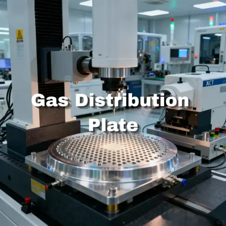
A gas distribution plate is a precision component that divides an incoming gas stream into many controlled flow paths before the gas enters a process chamber. In semiconductor equipment, it may contain hundreds of holes, internal passages, sealing surfaces, ports, coatings, and tightly controlled flat surfaces, so both flow design and machining quality affect final performance.
What Is Gas Distribution?
Gas distribution describes how an incoming gas stream is divided and delivered across a defined process area.
Instead of allowing gas to enter one location at high velocity, the plate creates many smaller flow paths. This helps distribute gas more evenly across the chamber or wafer area.
Flow behavior depends on inlet pressure, hole size, hole quantity, spacing, open-area ratio, channel geometry, and the pressure drop created by the plate. Each of these factors must remain consistent with the approved design.
How Does a Gas Distribution Plate Work?
Gas usually enters through one or more supply ports before reaching a plenum or internal channel network.
Pressure is redistributed inside this volume before the gas exits through the plate holes. Each hole creates a controlled amount of flow resistance, helping reduce local differences in gas delivery.
For manufacturing, the objective is therefore not simply to drill many holes. The plate must reproduce the designed flow resistance across the complete hole pattern.
Gas Distribution Plate vs Semiconductor Showerhead
A gas distribution plate and a semiconductor showerhead are related, but they are not always the same component.
The gas distribution plate is generally the part that controls or divides the gas flow. A showerhead may be a larger assembly containing the plate together with electrodes, plenums, bases, coatings, seals, or thermal interfaces.
Some designs use a standalone plate, while others use bonded or multi-layer structures. Understanding the exact assembly is important before selecting machining, coating, or leak-testing methods.
Where Are Gas Distribution Plates Used?
Gas distribution plates are used in semiconductor systems where process gases must enter a chamber with controlled flow, high cleanliness, and repeatable spatial distribution. They are commonly found in etching, deposition, process chamber, and gas delivery equipment, where poor flow uniformity or contamination can directly affect process consistency.
Plasma Etching Equipment
Etching systems use controlled gas chemistry to remove material from selected wafer areas.
A gas distribution plate or showerhead introduces the process gas across the chamber instead of concentrating it at a single inlet.
Because the plate operates close to the process region, hole condition, cleanliness, surface quality, and plasma-resistant coatings may all affect equipment performance.
Chemical Vapor Deposition Systems
CVD and PECVD systems use gases or precursors to form thin films on wafer surfaces.
The distribution plate helps balance gas before it reaches the deposition area. Uniform flow can help reduce local differences in concentration and residence time.
Internal channels, plenums, and outlet holes therefore need to work together as one gas delivery system rather than as separate machined features.
Atomic Layer Deposition Systems
ALD systems depend on highly controlled precursor exposure and purge cycles.
Poorly designed internal passages can create dead volumes where gas remains longer than intended. This can slow purging or allow unwanted mixing.
Machined channels should therefore use smooth transitions, clean intersections, and accessible geometry that can be properly cleaned after machining.
Process Chambers and Gas Delivery Systems
Gas distribution principles are also used in process chambers, manifolds, gas panels, and other delivery assemblies.
These parts may use fewer outlet holes but include more ports, threads, sealing interfaces, and intersecting internal passages.
For these components, leak integrity and internal cleanliness can be just as important as dimensional accuracy.
How Does Gas Distribution Design Affect Performance?
Gas distribution design determines how pressure is converted into controlled gas flow across the plate. Hole pattern, hole size, open area, pressure drop, internal channels, and dead volume are connected, so changing one feature can influence the behavior of the entire system. Manufacturing should therefore reproduce the approved design rather than modify flow-related features independently.
Hole Pattern and Open Area
Open area is the combined area of all gas holes compared with the usable surface area of the plate.
Increasing the open area generally reduces flow restriction, while reducing it increases resistance. However, the correct value depends on the intended flow design.
Hole quantity, diameter, spacing, and location should therefore remain consistent across the plate. Small geometric changes can alter the effective flow resistance of one region.
Hole Diameter and Hole Quantity
Hole diameter affects how much resistance each gas path creates.
The total number of holes determines how flow is divided across the available area. Hundreds or thousands of small holes can create a very different flow field from a smaller number of larger holes.
From a machining perspective, large hole counts also make tool wear important. Diameter drift or burr formation can gradually change as the drill processes more holes.
Pressure Drop and Flow Uniformity
Pressure drop is not always something that should be minimized.
In many gas distribution designs, controlled pressure drop helps equalize gas delivery by making individual outlet holes less sensitive to small upstream pressure differences.
This means consistent hole size and unobstructed passages are essential. A partially blocked hole or excessive coating buildup can create a different resistance from surrounding holes.
Internal Gas Channels and Flow Paths
Some gas distribution plates use internal channels to divide gas into multiple regions before it reaches the outlet holes.
These channels may connect different inlet ports, separate gas circuits, or feed specific zones across the plate.
Channel width, depth, intersections, corners, and sealing surfaces must therefore be machined consistently. If several layers are bonded together, the channel geometry must also support reliable sealing.
Dead Volume and Flow Imbalance
Dead volume is an area where gas can remain instead of moving efficiently toward the outlet holes.
Excessive dead space can affect purge behavior or create uneven residence times inside the gas delivery system.
Machining should therefore avoid unintended pockets, incomplete channel intersections, trapped chips, and excessive corner material that could alter the designed flow path.
What Materials Are Used for Gas Distribution Plates?
Gas distribution plate materials are selected according to gas chemistry, plasma exposure, temperature, contamination limits, mechanical requirements, vacuum conditions, and surface treatment. Aluminum and stainless steel are common machined materials, while silicon carbide and ceramic-based materials may be selected for more demanding plasma or chemical environments.
Aluminum Alloys
Aluminum alloys are widely used because they machine efficiently, conduct heat well, and support several surface treatment options.
They are suitable for large plates containing extensive drilling, pockets, channels, and sealing features.
However, large aluminum plates can distort as internal stress is released during machining. Roughing and final finishing may therefore need to be separated so the part can stabilize before final flatness is produced.
Stainless Steel
316L stainless steel may be used for gas-wetted parts where corrosion resistance and chemical compatibility are important.
Compared with aluminum, stainless steel usually creates higher cutting loads and more heat during drilling and milling.
Small-hole machining therefore requires appropriate cutting parameters, coolant delivery, rigid tooling, and controlled tool life to maintain hole quality.
Silicon Carbide and Ceramic Materials
Silicon carbide, alumina, yttria-based ceramics, silicon, and other advanced materials may be selected for plasma-facing or chemically demanding applications.
Their advantages can include plasma resistance, electrical characteristics, chemical stability, and reduced contamination.
However, these materials may require grinding, laser drilling, specialized machining, or other processes instead of conventional metal CNC methods.
How to Select Materials for Process Conditions
Material selection should begin with the actual semiconductor process environment.
Engineers should consider plasma exposure, corrosive gases, vacuum, operating temperature, cleaning chemistry, thermal behavior, and contamination requirements.
Machinability is important, but it should not override the functional requirements of the gas distribution system.
What Should Be Considered Before CNC Machining a Gas Distribution Plate?
Before CNC machining begins, the gas distribution plate should be reviewed as a functional flow and sealing component. Functional datums, flatness, sealing surfaces, hole groups, internal channels, coating allowances, and assembly interfaces should be identified early so the machining plan protects the features that directly affect gas flow and equipment performance.
Define Functional Datums and Critical Surfaces
Functional datums should reflect how the plate locates inside the final assembly.
A sealing surface, locating bore, or mounting feature may also control the position of the gas hole pattern.
Using the same functional references during machining and inspection helps reduce tolerance stack-up and improves consistency between production batches.
Control Plate Thickness and Flatness
Large plates can distort when material is removed from one side or when excessive clamping force is applied.
Flatness should therefore be managed throughout machining rather than corrected only during the final operation.
Balanced stock removal, controlled fixturing, intermediate relaxation, and light finishing passes can help maintain stable plate geometry.
Plan Hole Layout and Edge Distance
Hole arrays should be reviewed for spacing, edge distance, depth, tool access, and proximity to internal channels.
Holes near channel walls or sealing surfaces may require additional control because breakthrough position and burr formation can affect nearby features.
Dense patterns may also need to be drilled in planned groups to manage heat, chip evacuation, and tool wear.
Design Internal Gas Channels for Machining
Internal channels should provide realistic cutter access and allow effective cleaning after machining.
Very narrow passages, deep cavities, sharp internal corners, and inaccessible intersections can increase machining time and create cleaning problems.
Where channels will later be sealed by bonding or another joining method, sealing lands should also provide sufficient width and flatness.
Consider Sealing and Assembly Interfaces
Gas distribution plates may contain O-ring grooves, sealing lands, threaded ports, alignment holes, and mounting faces.
Each interface can have different dimensional and surface requirements.
The machining process should identify these features early so they remain protected during drilling, deburring, coating, cleaning, and final handling.
How Is a Gas Distribution Plate CNC Machined?
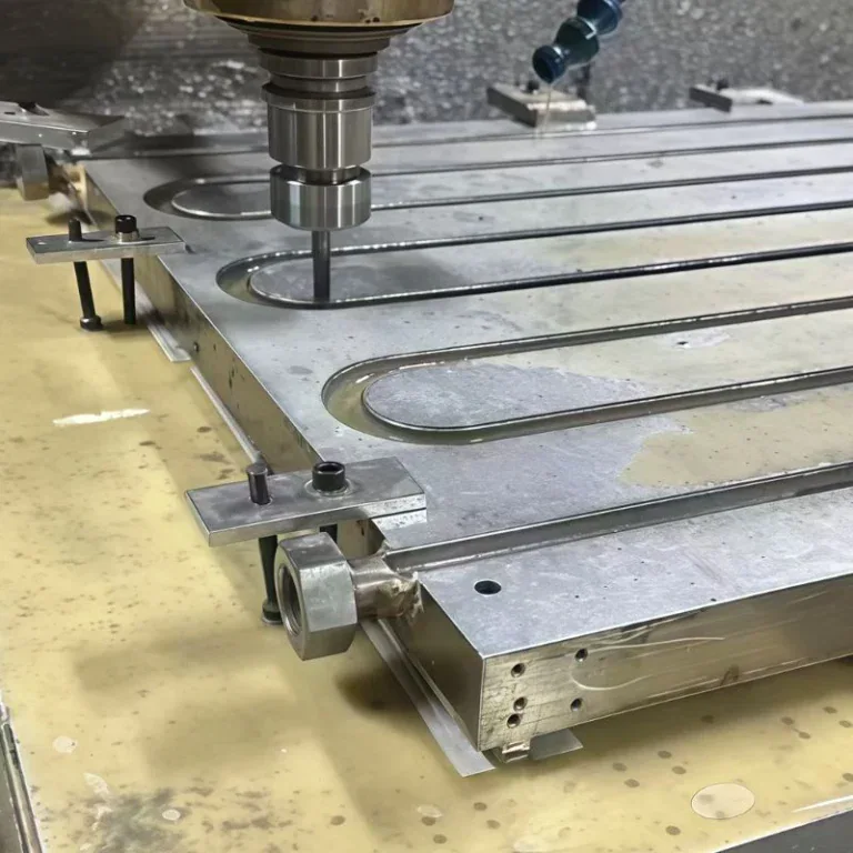
Gas distribution plate machining generally begins with stable datum surfaces and balanced rough machining, followed by channel formation, hole drilling, port machining, and final finishing of critical sealing surfaces. The sequence should minimize distortion and protect the relationship between the hole pattern, internal gas passages, and functional interfaces.
Plate Preparation and Rough Machining
The raw material should first be checked for the correct grade, condition, and machining allowance.
Reference surfaces are then established before large amounts of material are removed.
For large plates, balanced roughing is important. Removing too much material from one side can release residual stress and create distortion before the precision operations begin.
Precision Milling and Flatness Control
Precision milling establishes the final plate thickness, outside geometry, locating features, and major sealing surfaces.
Most heavy stock removal should be completed before the final flatness operation.
Light finishing passes and low-stress workholding can reduce the risk of clamping distortion being transferred into the finished surface.
Internal Channel Machining
Internal gas channels may be milled into a single plate or into separate layers that are later joined.
Channel depth, width, junction geometry, and sealing lands should remain consistent across the part.
Sharp tool marks, trapped chips, incomplete intersections, and unintended pockets should be avoided because these areas can affect both gas flow and cleaning.
Ports, Threads, and Connection Features
Gas inlet ports and threaded connections must align correctly with the internal flow network.
Thread quality is important because damaged threads can create particles during assembly.
Port faces may also act as sealing interfaces, so perpendicularity, surface finish, and dimensional control may be required around these features.
Final Machining of Sealing and Functional Surfaces
Critical sealing and locating surfaces are normally finished after the major roughing and drilling operations are complete.
These may include chamber-facing surfaces, gasket lands, O-ring grooves, mounting faces, and alignment features.
Once finished, these areas should be protected through coating, cleaning, inspection, packaging, and shipment.
How Is Gas Distribution Plate Drilling Controlled?
Gas distribution plate drilling is one of the most sensitive manufacturing stages because errors repeated across hundreds of holes can directly change gas flow. Hole diameter, position, tool runout, drill wear, burr condition, breakthrough quality, and cleanliness should therefore be controlled throughout the drilling process rather than checked only after all holes are complete.
Hole Diameter and Position Accuracy
Hole diameter determines flow resistance, while hole position determines where the gas is delivered.
Large hole arrays require a stable CNC coordinate system, reliable workholding, and accurate tool offsets.
Inspection should verify representative areas across the plate so coordinate drift, local pattern errors, or gradual diameter changes can be detected.
Small and High-Aspect-Ratio Hole Drilling
Small holes become more difficult as their depth increases relative to diameter.
Chip evacuation becomes harder, drill rigidity decreases, and cutting heat becomes more difficult to control.
Depending on the geometry, the process may require peck drilling, through-tool coolant, specialized carbide drills, or alternative methods such as laser drilling.
Tool Runout and Drill Wear
Tool runout can enlarge a hole and accelerate uneven wear.
Before long drilling cycles, the drill and holder should be checked for stable runout.
For plates with large numbers of identical holes, tool life may be controlled by hole count so the drill can be replaced before diameter, burr size, or surface quality begins to drift.
Burr and Breakthrough Control
Burrs can reduce the effective opening of a gas hole or become loose particles during operation.
Breakthrough burrs are particularly difficult when the hole enters an internal channel.
Tool geometry, drilling direction, support conditions, feed strategy, and controlled deburring should therefore be planned as part of the same manufacturing process.
Hole Cleaning and Through-Hole Verification
A hole can meet its dimensional tolerance and still fail functionally if chips, coating residue, or burr fragments remain inside.
Final inspection should confirm that every required gas path is open.
Depending on the hole size and part design, manufacturers may use optical inspection, calibrated pins, wire checks, airflow verification, or another validated method.
How Are Surface Finish and Coatings Applied?
Surface treatment is used to improve corrosion resistance, plasma resistance, chemical compatibility, cleanliness, or contamination control. Because coatings can change hole diameter, sealing geometry, and final dimensions, surface treatment should be planned together with machining rather than treated as an independent operation added after the part is finished.
Surface Roughness on Gas-Wetted Areas
Gas-wetted surfaces should be free from loose burrs, embedded particles, and severe machining damage.
The required roughness depends on the drawing and process environment.
A smoother surface can improve cleanability and reduce areas where contamination or process residue can remain, but unnecessarily low Ra requirements can increase manufacturing cost.
Anodizing and Alumina Protective Layers
Aluminum gas distribution plates may be anodized for surface protection and process compatibility.
Because anodizing changes the surface layer, precision holes, threaded regions, sealing areas, and fits may require masking or dimensional compensation.
The drawing should clearly identify which surfaces are coated and which must remain untreated.
Yttria and Ceramic Coatings
Yttria-based and ceramic coatings may be used on components exposed to aggressive plasma conditions.
These coatings can improve resistance to erosion and chemical attack.
However, coating buildup around small gas holes can reduce their effective diameter, so hole condition should be inspected after the coating process.
Electropolishing and Passivation
Stainless steel gas distribution components may require electropolishing or passivation.
Electropolishing can improve surface smoothness and cleanability, while passivation supports corrosion resistance after machining.
Because electropolishing removes a small amount of material, critical dimensions should account for the finishing process before final machining sizes are established.
How Coating Thickness Affects Holes and Dimensions
Coating thickness can reduce small hole diameters and alter precision interfaces.
Depending on the design, holes may be intentionally oversized before coating or reopened after coating.
The final manufacturing plan should define the correct sequence and verify the finished hole condition rather than relying only on pre-coating inspection.
How Are Gas Distribution Plates Cleaned and Inspected?
Gas distribution plate inspection should focus on the characteristics that control flow, sealing, cleanliness, and assembly. Dimensional inspection alone is not enough when hole condition, flatness, surface roughness, coating quality, internal channel integrity, and particle control can affect process performance.
Dimensional and CMM Inspection
CMM inspection can verify hole patterns, ports, grooves, datums, mounting features, and geometric relationships.
The inspection coordinate system should follow the same datum structure used on the engineering drawing.
Critical dimensions can also be checked during machining so tool offsets or process conditions can be corrected before final acceptance.
Hole Diameter and Pattern Inspection
Hole inspection should verify both size and location.
Optical measurement can be useful for dense patterns, while calibrated pins or gauges may be suitable for larger holes.
The inspection plan should also detect missing, partially drilled, or blocked holes rather than checking only selected diameters.
Flatness and Sealing Surface Inspection
Flatness can be measured with a CMM, surface plate, indicator, optical system, or another suitable method.
The plate should be supported in a way that does not artificially flatten it during measurement.
This is especially important for thin or large plates that can deform under their own weight or under excessive inspection clamping.
Surface Roughness and Coating Inspection
Surface roughness should be measured on the locations defined by the drawing.
Coating inspection may include thickness, coverage, adhesion, visual condition, and edge quality.
Gas holes should also be checked after coating to confirm that the openings remain clear and within the required condition.
Leak Testing of Internal Gas Channels
Plates with sealed internal channels can pass dimensional inspection and still contain an internal leak.
Leak testing is therefore required when channel integrity is a functional requirement.
The acceptance limit should come from the customer’s drawing or equipment specification instead of using a generic leak standard for every gas distribution plate.
Precision Cleaning and Protective Packaging
Final cleaning removes machining oil, chips, abrasive residue, fingerprints, particles, and finishing contamination.
The cleaning method should be compatible with the material and surface coating.
After cleaning, ports, sealing faces, and precision surfaces should be protected so the part does not become contaminated or damaged during inspection, storage, and transportation.
What Common Defects Affect Gas Distribution Plates?
The most serious gas distribution plate defects are those that change flow resistance, create contamination, reduce sealing performance, or allow internal leakage. Hole errors, burrs, blocked passages, plate warpage, channel leaks, and coating defects should therefore be linked to specific machining and inspection controls rather than treated as cosmetic problems.
Incorrect Hole Diameter or Position
Incorrect hole diameter changes local gas resistance.
Incorrect position changes where the gas enters the process region.
A local error in one section of the pattern can therefore create an imbalance even when most of the plate remains within specification.
Burrs, Particles, and Blocked Holes
Burrs may detach during cleaning, assembly, or equipment operation.
Particles can also remain trapped inside channels if the cleaning process cannot reach them.
For this reason, drilling, deburring, cleaning, and final through-hole verification should be treated as one connected quality process.
Warpage and Flatness Errors
Warpage can prevent proper sealing or change the alignment between the plate and surrounding chamber hardware.
Distortion may be caused by residual material stress, unbalanced machining, excessive clamping, cutting heat, or coating processes.
Flatness control should therefore begin during rough machining and continue through final inspection.
Internal Channel Leakage
A multi-layer plate may meet every external dimension and still leak internally.
A leak can allow gases to bypass the intended flow path or mix between separate circuits.
Where internal channels are bonded or sealed, leak integrity should be verified as a functional requirement.
Surface and Coating Defects
Scratches, pits, coating voids, flaking, or excessive buildup can reduce component reliability.
The importance of a defect depends on where it is located.
A cosmetic mark on an external surface may have little effect, while the same defect on a sealing face or gas-wetted area can be unacceptable.
How Do Manufacturing Requirements Affect Cost and Lead Time?
Gas distribution plate cost is mainly influenced by hole count, hole complexity, plate flatness, tolerance level, internal channel design, material, surface finish, coating, cleaning, testing, and inspection. Applying tight requirements only to features that control gas flow, sealing, cleanliness, or assembly can reduce cost without sacrificing functional performance.
Hole Count and Hole Complexity
Hundreds of small holes can create significant drilling time.
Cost increases further when the holes are very small, deep, tightly positioned, or require frequent tool replacement.
The hole pattern should therefore be based on actual gas flow requirements rather than using unnecessarily small or numerous holes.
Flatness and Dimensional Tolerances
Tighter flatness can require more controlled roughing, stress relief, finishing passes, re-fixturing, and inspection.
The same is true for tight parallelism, thickness, and positional tolerances.
Drawings should separate critical sealing and alignment features from noncritical external geometry whenever possible.
Internal Channel Complexity
Deep, narrow, or multi-zone channels increase programming and machining time.
Multi-layer plates may also require bonding, brazing, welding, or another sealing method followed by leak testing.
Simplifying the channel layout while preserving the required flow function can improve manufacturing reliability and reduce lead time.
Surface Finish and Coating Requirements
Fine surface requirements may require additional finishing operations.
Coating adds masking, supplier coordination, dimensional compensation, inspection, and possible rework.
These requirements should be defined before quotation because they affect both machining allowance and total production time.
Cleaning, Testing, and Inspection Requirements
Semiconductor-grade parts may require controlled cleaning, special packaging, CMM inspection, roughness measurement, coating verification, and leak testing.
These operations add cost, but they also protect process reliability.
A clear quality specification helps the supplier apply these controls only where they are required.
FAQs
How Small Can Gas Distribution Plate Holes Be CNC Drilled?
The practical minimum depends on hole depth, material, aspect ratio, quantity, tolerance, and burr requirements. Small shallow holes in aluminum are easier than deep holes of the same diameter in stainless steel. As the diameter decreases or depth increases, micro-drilling, specialized tooling, or laser drilling may become more suitable.
Does Every Gas Distribution Plate Need Extremely Tight Flatness?
No. Flatness should be based on sealing, assembly, chamber geometry, and equipment function. A plate used as a sealing datum may require tighter control than a non-sealing distributor. Unnecessarily tight flatness increases machining and inspection cost without automatically improving gas flow.
Should Holes Be Drilled Before or After Coating?
The correct sequence depends on the coating system and design. Some holes are machined before coating with dimensional compensation, while other designs may require the openings to be restored after coating. Final inspection should always confirm that the coated holes remain open and within specification.
How Can a Supplier Verify Gas Distribution Plate Quality?
Quality verification should cover hole size and position, flatness, sealing surfaces, surface roughness, coating condition, internal channel integrity, cleanliness, and material traceability. Where sealed internal passages are used, leak testing should also be included when required by the drawing.
Conclusion
Gas distribution plate performance depends on the connection between fluid design and manufacturing control. Hole pattern, pressure drop, internal channel geometry, material behavior, plate flatness, drilling quality, surface condition, coating, cleaning, and inspection all influence how reliably gas reaches the process chamber. A stable manufacturing process should identify critical flow and sealing features early, protect them through each production stage, and verify them using inspection methods matched to their actual function.
At TiRapid, we provide precision CNC machining and manufacturing services for semiconductor equipment components, including complex plates, manifolds, internal channels, precision hole patterns, sealing surfaces, and engineering materials. Our team supports DFM, multi-axis machining, dimensional inspection, surface finishing coordination, and controlled production to help customers achieve stable part quality and repeatable manufacturing.