Natural gas pipeline systems require stable and reliable operation over long periods. Precision components are essential for pipeline distribution, metering, pressure regulation, and drainage equipment. Dimensional deviations, inaccurate hole positions, or mismatched interfaces can affect equipment assembly, gas flow control, and future maintenance. For natural gas equipment manufacturers, choosing the right CNC machining solution helps improve component consistency and supports custom designs and batch production. CNC turning, milling, drilling, and precision inspection can be used to manufacture custom components for different pipeline applications.
Advantages of CNC Machining for Natural Gas Pipeline Components
Natural gas pipeline components must fit accurately with metering equipment, pressure regulators, distribution systems, and auxiliary pipelines. Their machining quality directly affects installation efficiency and long-term equipment stability. As natural gas equipment becomes more integrated and customized, components require higher dimensional accuracy, more complex structures, and consistent production quality. CNC machining allows manufacturers to adjust processes according to digital drawings and produce components in different sizes and configurations.
Precision Machining Improves Equipment Interface Fit
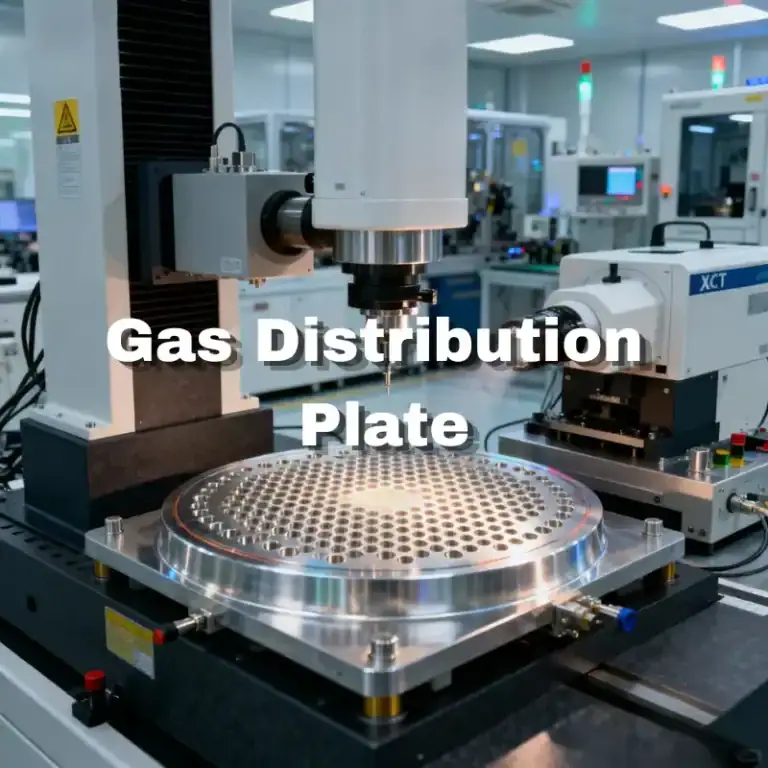
Natural gas pipeline components are commonly used with valves, metering devices, pressure regulators, and pipeline assemblies. Some parts feature multiple holes, stepped bores, positioning grooves, and irregular mounting surfaces. Conventional machining methods may struggle to maintain consistent dimensions across these structures. CNC machining controls tool paths according to digital drawings, reducing manual errors and maintaining stable hole spacing, concentricity, surface flatness, and installation dimensions.
For equipment that requires repeated assembly, precision machining also improves component interchangeability and reduces on-site adjustment work. Proper machining references and clamping methods help minimize cumulative errors caused by repeated positioning, allowing components to fit the overall equipment structure more accurately.
Custom Structures Meet Different Pipeline Equipment Requirements
Natural gas transportation systems have different equipment layouts and interface designs. Some projects require compact connection components, while others need custom parts with multiple instrument ports, mounting holes, or support structures. CNC machining programs can be adjusted according to customer-provided CAD drawings, 3D models, and technical specifications.
Common customization requirements include:
- Custom connection bases: Irregular shapes, positioning steps, and mounting holes designed to fit specific equipment spaces.
- Instrument interface components: Mounting interfaces for pressure, temperature, and flow monitoring devices.
- Distribution manifolds: Multiple flow channels, branch holes, and connection points designed according to pipeline layouts.
- Pressure regulator connectors: Matching mounting structures for pressure regulators, actuators, and auxiliary equipment.
Custom machining reduces compatibility issues between standard components and specialized equipment. It also allows manufacturers to adjust product dimensions and structures according to project requirements.
Multiple Machining Processes Handle Complex Component Structures
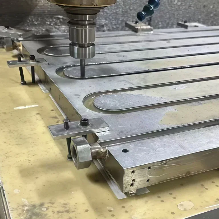
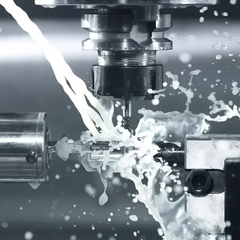
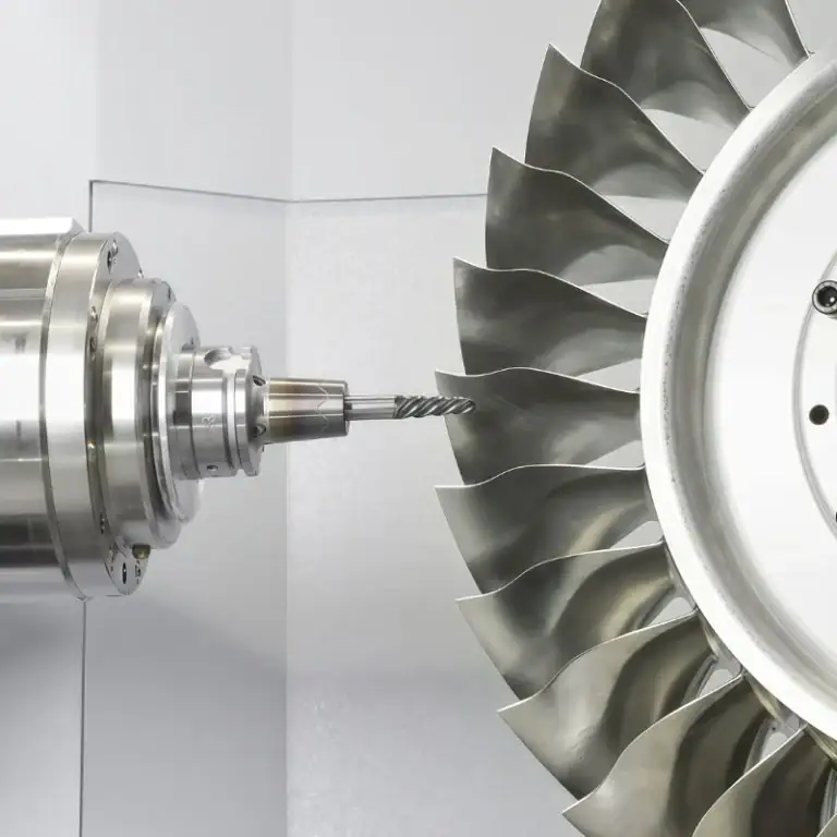
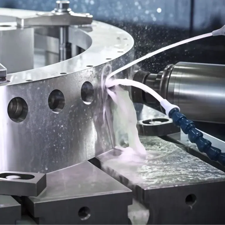
Natural gas pipeline components may contain cylindrical surfaces, flat surfaces, internal bores, side holes, threads, and sealing structures. CNC turning can be used to machine shaft profiles and precision internal bores. CNC milling is suitable for mounting surfaces, slots, and irregular contours, while drilling, tapping, and finishing operations complete the interface structures.
For components with complex designs, a well-planned machining sequence can reduce repeated clamping and improve production efficiency. Material selection, cutting tools, machining parameters, and surface treatments should also be determined according to actual operating conditions. Machining accuracy alone cannot determine the final performance of a component.
Machining Methods and Applications of Natural Gas Pipeline Components
Different natural gas equipment requires different component structures and machining processes. Parts used in metering stations, pressure regulation stations, distribution systems, and drainage equipment may include multiple holes, internal flow channels, irregular mounting surfaces, and precision interfaces. Selecting suitable CNC turning, milling, drilling, and tapping processes helps improve machining efficiency and assembly compatibility. Developing a machining plan for each application also helps control product quality and production costs.
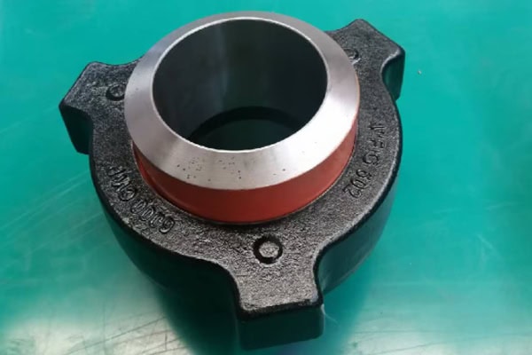
CNC Machining Process for Natural Gas Pipeline Components
The quality of custom components depends on drawing confirmation, process planning, and final inspection. Before machining begins, manufacturers need to confirm the component’s installation position, interface type, material grade, dimensional tolerances, and operating conditions. Suitable equipment and machining sequences can then be selected according to the component structure.
A typical CNC machining process includes:
- Drawing and technical review: Check 3D models, dimensions, tolerances, material standards, and critical interfaces.
- Material preparation: Select suitable materials according to the media, design pressure, and applicable standards. Verify material certificates.
- CNC programming: Prepare turning, milling, drilling, and tapping programs while planning clamping references and machining sequences.
- Component machining: Complete external profiles, internal bores, flow channels, positioning surfaces, and mounting structures.
- Deburring and surface treatment: Remove burrs from holes and edges, then apply suitable surface treatments according to technical requirements.
- Dimensional inspection: Use calipers, micrometers, coordinate measuring machines, or dedicated gauges to check critical dimensions.
- Quality documentation: Prepare inspection reports, material records, and product identification according to project requirements.
A clearly defined machining process helps maintain dimensional consistency between production batches and supports customer incoming inspection and equipment assembly.
Connection Components for Metering and Pressure Regulation Equipment
Natural gas metering and pressure regulation stations commonly use flow meters, pressure transmitters, pressure regulators, and auxiliary control equipment. These devices require dedicated connection bases, mounting plates, instrument fittings, and positioning components. CNC machining can produce different component specifications according to equipment models and installation spaces, ensuring that instrument interfaces match the pipeline layout.
In metering equipment, connection components must maintain accurate installation positions to prevent interface deviations from affecting assembly. Some metering systems also require sensor brackets and instrument mounting bases. These parts often feature precision holes, positioning steps, and specific mounting dimensions. CNC milling and drilling can produce these structures according to design requirements, making installation and maintenance easier.
In pressure regulation equipment, connection components may also support actuator mounting, auxiliary pipeline connections, and equipment positioning. For equipment designed for long-term operation, material properties, sealing requirements, and inspection procedures should be confirmed according to the actual operating conditions and applicable engineering standards.
Machining Requirements for Distribution Manifolds and Drainage Components
Distribution manifolds connect main pipelines with multiple branch lines. They usually contain several flow channels, intersecting holes, and external mounting interfaces. The key machining requirements include hole positioning, internal channel geometry, and dimensional relationships between different interfaces. CNC milling and drilling can produce branch holes, mounting surfaces, and positioning structures according to the design. For components with complex internal channels, the machining plan should also consider chip removal, deburring, and internal cleaning.
Drainage components are commonly installed at low points in pipelines, equipment collection areas, and auxiliary discharge systems. These parts may include drainage ports, valve mounting bases, and pipeline transition structures. Machining must control flow channel dimensions, interface positions, and internal surface conditions to prevent machining residues from affecting assembly or operation. Actual design and manufacturing should follow applicable engineering standards, with pressure and sealing verification performed when required by the operating conditions.
| Component Type | Common Material Options | CNC Machining Processes | Key Quality Requirements | Typical Applications |
| Instrument mounting base | Stainless steel, suitable aluminum alloys | Milling, drilling, tapping | Hole position accuracy, mounting surface flatness | Pressure and temperature monitoring equipment |
| Distribution manifold | Carbon steel, alloy steel, stainless steel | Milling, drilling, internal bore machining | Flow channel dimensions, hole positions, internal cleanliness | Natural gas branch distribution systems |
| Pressure regulator connection base | Steel or stainless steel selected according to design requirements | Turning, milling, drilling | Positioning accuracy, structural dimensions, interface fit | Pressure regulators and actuators |
| Drainage component | Stainless steel, carbon steel | Turning, milling, drilling | Flow channel dimensions, interface accuracy, surface condition | Pipeline low points and equipment drainage systems |
| Metering equipment support | Aluminum alloys, carbon steel, stainless steel | Milling, drilling, tapping | Mounting dimensions, rigidity, hole spacing accuracy | Flow meters and metering skid equipment |
Function and Performance Control of Natural Gas Pipeline Components
Natural gas pipeline components must meet equipment assembly requirements while operating under specific pressure, temperature, and media conditions. Dimensional accuracy, material properties, surface conditions, and internal cleanliness can all affect equipment performance. Standardized dimensional inspection, material verification, and necessary performance testing help confirm whether components meet project specifications and provide reliable connections for natural gas pipeline systems.

Inspection of Critical Dimensions, Flow Channels, and Machining Quality
The dimensional accuracy of pipeline components affects equipment installation and pipeline compatibility. For parts with multiple holes and internal flow channels, inspection should cover more than external dimensions. Hole spacing, bore diameter, depth, concentricity, perpendicularity, and critical end-face conditions should also be checked. Coordinate measuring machines, bore gauges, thread gauges, and dedicated inspection tools can be selected according to drawing tolerances.
Key inspection items before delivery include:
- Interface dimensions: Check internal and external diameters, thread specifications, hole sizes, and connection positions.
- Geometric accuracy: Inspect concentricity, flatness, perpendicularity, and critical positioning dimensions.
- Surface quality: Check sealing surfaces, flow channels, and machined edges for scratches, burrs, or visible defects.
- Internal cleanliness: Ensure that flow channels are free from machining chips, cutting fluids, and other contaminants.
- Inspection records: Keep dimensional inspection data and material traceability records according to order requirements.
For components with pressure or sealing requirements, dimensional inspection cannot replace pressure testing, leak testing, or other required verification procedures. These inspections should be performed by qualified personnel according to applicable standards.
Corrosion Resistance, Pressure Suitability, and Long-Term Performance
Natural gas pipeline equipment may operate outdoors, in areas with significant temperature changes, or in environments containing moisture and corrosive substances. Material selection for pipeline components should consider design pressure, operating temperature, media composition, corrosion conditions, and expected service life. Carbon steel, alloy steel, and stainless steel each have suitable applications. Material names alone cannot confirm whether a component meets the requirements of a specific project.
CNC machining helps control component dimensions and structural quality, but the final pressure-bearing capability also depends on material properties, wall thickness design, heat treatment, welded structures, manufacturing standards, and inspection results. Components used in high-pressure natural gas pipelines, wellsite equipment, or other demanding applications must undergo material verification, nondestructive testing, pressure testing, or sealing tests as required by project specifications.
In batch production, stable machining programs, standardized tool management, and complete quality records help reduce variations between production batches. Before manufacturing begins, suppliers should also confirm drawing revisions, material certificates, surface treatments, inspection standards, and delivery documents with customers. This helps ensure that machined components meet actual equipment assembly and operating requirements.
CNC machining of natural gas pipeline components requires a balance of custom structural design, dimensional accuracy, material suitability, and quality verification. With suitable CNC turning, milling, and precision inspection processes, manufacturers can supply custom components for metering stations, pressure regulation stations, distribution systems, and auxiliary pipeline equipment. For projects with special operating conditions, confirming technical drawings and inspection specifications in advance helps improve purchasing compatibility and assembly efficiency.