
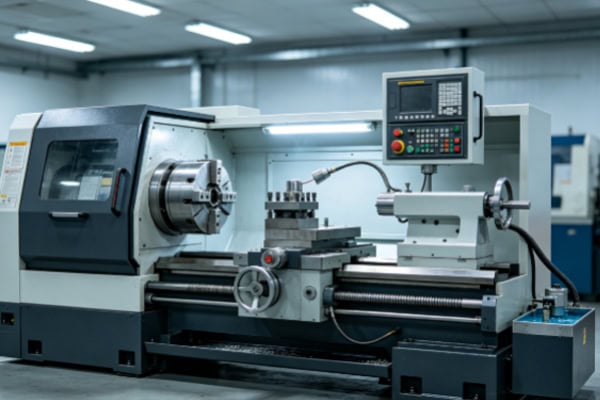
CNC turning equipment is an automated machining system that uses a computer numerical control system to manage machine movements and machining operations. The spindle rotates the workpiece while cutting tools move along programmed axes to remove material and produce the required geometry. Compared with conventional lathes, CNC turning equipment incorporates numerical control systems, servo drives, automatic tool changing mechanisms, position feedback devices, and programmable machining functions, allowing production processes to run continuously according to predefined programs. A typical CNC lathe consists of a machine bed, headstock, spindle system, chuck, tool turret, cutting tools, slides, guideways, ball screws, tailstock, CNC control system, servo motors, coolant system, lubrication system, and protective enclosure. Different machines may also include driven tools, a sub-spindle, C-axis control, automatic bar feeders, and in-process inspection equipment. These components do not operate independently. They work together through mechanical structures, electrical control systems, and machining software to form a complete manufacturing system. The spindle provides rotational power, the chuck secures the workpiece, the turret selects and positions cutting tools, the slides and ball screws control tool movement, and the CNC system coordinates the entire machining process. Understanding the basic components of CNC turning equipment helps manufacturers select suitable machines, maintain equipment properly, identify potential faults, and develop more efficient machining processes.
Main Mechanical Structure of CNC Turning Equipment
The mechanical structure of CNC turning equipment provides the foundation for support, positioning, transmission, and cutting-load resistance. During machining, the spindle rotates at high speed while the cutting tool moves according to the programmed path. If machine rigidity is insufficient, guideway accuracy deteriorates, or transmission components develop excessive backlash, problems such as vibration, dimensional deviation, and poor surface finish may occur. Modern CNC lathes generally use rigid machine structures combined with guideways, slides, and ball screws to provide stable tool movement. These systems allow the machine to perform external turning, facing, internal boring, grooving, threading, and other machining operations with consistent accuracy. The manufacturing quality, installation accuracy, and long-term stability of the mechanical structure have a direct influence on the overall machining performance of CNC turning equipment.
Machine Bed and Base
The machine bed is one of the most important structural components of a CNC turning machine. The headstock, guideways, slides, and tailstock are mounted on or connected to the machine bed. The bed must have sufficient rigidity and stability to withstand cutting loads and vibration generated during machining. A rigid machine bed reduces structural deformation and helps maintain a stable relationship between the cutting tool and workpiece. Some CNC lathes use slant-bed designs to improve chip evacuation and facilitate automated loading and unloading as well as maintenance operations.
- Supports the headstock and motion systems
- Provides overall machine rigidity
- Supports guideways and slides
- Reduces machining vibration
- Improves long-term machine stability
- Maintains installation accuracy
- Improves cutting-force distribution
Although the machine bed does not directly perform cutting, it provides the structural foundation for the entire machining system. On precision CNC turning machines, the stability of the bed can affect the relative position of the spindle, turret, and motion axes. Changes in machine installation or foundation conditions over long periods can also influence dimensional consistency, making proper machine installation and leveling important.
Guideways, Slides, and Ball Screw System
Guideways and slides control linear tool movement. Common movement directions include the X and Z axes. The Z axis is generally parallel to the spindle centerline and controls axial tool movement, while the X axis controls radial movement and machining diameter. Ball screws convert the rotary motion of servo motors into linear slide movement and provide accurate positioning during machining.
- Controls axial tool movement
- Controls radial tool movement
- Improves positioning accuracy
- Reduces transmission backlash
- Maintains repeatability
- Supports continuous automatic machining
Guideway condition, ball screw accuracy, and lubrication all influence motion stability. If guideways become worn or excessive backlash develops in the ball screw system, the actual tool path may deviate from the programmed path. During daily production, guideways should be kept clean, lubrication should be checked regularly, and machine positioning accuracy should be inspected according to maintenance requirements.
Spindle and Workholding System of CNC Turning Equipment
The spindle system is one of the core power systems of CNC turning equipment. It drives the chuck and workpiece during machining. A major characteristic of turning compared with milling is that the workpiece is generally rotated by the spindle while the cutting tool performs controlled feed movements. Spindle speed, rotational stability, and workholding condition directly influence cutting efficiency, surface quality, and dimensional accuracy. A chuck or collet is normally mounted at the front of the spindle to secure different types of workpieces. Advanced turning centers may also include C-axis control, a sub-spindle, or driven tools, allowing more complex machining operations to be completed on a single machine.
Headstock and Spindle System
The headstock is generally installed at one end of the machine bed and contains the spindle, bearings, drive components, and related transmission mechanisms. The spindle is driven by a motor, while the CNC system controls its speed and rotational direction according to machining requirements. Spindle accuracy has a major influence on roundness, concentricity, and surface quality. During high-speed machining, spindle balance and thermal stability also need to be considered.
The spindle system must provide sufficient rotational rigidity while supporting different materials and workpiece dimensions. Aluminum alloys may require relatively high spindle speeds, while stainless steel and alloy steel usually require carefully selected speeds based on tool performance and cutting conditions. Stable spindle operation helps reduce vibration and maintain consistent cutting performance.
Chucks and Collets
The chuck secures the workpiece to the spindle so that it rotates reliably with the spindle. Common workholding devices include three-jaw chucks, four-jaw chucks, and collets. Three-jaw chucks are suitable for many regular rotational components, four-jaw chucks provide independent jaw adjustment for flexible positioning, and collets are often used for bar stock and small precision components. Clamping force should be selected according to the material and geometry of the workpiece. Insufficient clamping force can cause workpiece slipping, while excessive force can deform thin-walled components.
- Secures the workpiece
- Maintains rotational stability
- Reduces setup errors
- Improves repeatability
- Supports different workpiece sizes
- Enables batch production
Proper workholding selection improves CNC turning stability. For precision components, the clamping method should also consider reference surfaces, machining allowances, and component rigidity to maintain stable workpiece positioning throughout the cutting process.
Tailstock and Centering Mechanism
The tailstock is positioned opposite the headstock and is mainly used to support long or slender workpieces. Long shafts supported only by the chuck can bend or vibrate during machining. A tailstock combined with a center provides additional support rigidity and reduces machining deformation. Some CNC lathes use programmable tailstocks that can move and position automatically, improving production efficiency during batch machining.
- Supports long shafts
- Reduces machining vibration
- Minimizes workpiece deflection
- Improves slender-shaft machining stability
- Improves surface quality
- Enhances dimensional consistency
For short workpieces, the tailstock may not be required. For slender shafts and long components, proper tailstock use can significantly improve machining stability.
Cutting Tools and Automatic Tool Changing System
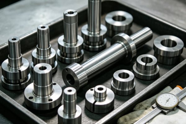
Cutting tools are the direct machining elements of CNC turning equipment. Different workpieces require different tools for rough external turning, finish turning, facing, internal boring, grooving, parting, and threading. Modern CNC lathes generally use a turret that can hold multiple cutting tools and automatically select the required tool according to the program. The turret rotates to position the selected tool at the machining position, reducing manual tool-changing time and improving continuous production efficiency.
Tool Turret and Tool Mounting System
The tool turret is a key component of the automatic tool-changing system. It normally contains multiple tool stations, allowing different tools to be installed according to the machine configuration. The turret must not only provide rapid tool changes but also maintain accurate and repeatable tool positioning. For batch production, a well-designed tool configuration allows multiple machining operations to be completed in a single setup.
- Install external turning tools
- Install internal boring tools
- Install grooving tools
- Install parting tools
- Install threading tools
- Configure form tools
- Support driven tools on selected machines
Proper turret configuration reduces tool changes and auxiliary time, allowing roughing, semi-finishing, and finishing operations to be completed more efficiently. Turning centers equipped with driven tools can also perform drilling, milling, and tapping operations, increasing the machining capability of a single machine.
Turning Tools and Insert Systems
Turning tools generally consist of tool holders, cutting inserts, and clamping mechanisms. Modern CNC machining commonly uses indexable inserts, with insert material, coating, nose radius, and chip-breaker geometry selected according to the workpiece material and machining requirements. When machining carbon steel, wear resistance and cutting stability are important. Aluminum alloys generally require sharp cutting edges and effective chip evacuation. Stainless steel requires a balance of toughness, wear resistance, and edge strength.
Tool condition directly affects component dimensions and surface quality. As inserts wear, cutting forces may increase and surface roughness can deteriorate. Production teams can establish tool replacement standards based on machining quantity, cutting time, and actual wear condition to maintain stable cutting performance.
CNC Control and Drive Systems
The CNC control system is the central control component that enables automated machining. After the operator inputs a machining program, the control system interprets the instructions and coordinates the spindle, servo motors, turret, and motion axes according to the programmed tool path. The CNC system manages program execution, coordinate settings, tool compensation, spindle speed, feed rate, alarm monitoring, and program storage.
CNC Control Panel
The control panel is an important interface between the operator and the machine. It normally includes a display, keyboard, function buttons, and operating switches. Operators can use the control panel to call machining programs, modify parameters, set work coordinates, enter tool compensation values, and check machine alarms.
- Input and call CNC programs
- Set machining coordinates
- Adjust tool compensation
- Set spindle speed
- Set feed parameters
- Monitor machine status
- Check alarm information
- Manage program files
Operators should configure parameters according to machine documentation and production requirements. Incorrect coordinate settings, tool compensation values, or program selection can lead to machining errors.
Servo Motors and Drive Mechanisms
Servo motors drive the X and Z axes and other motion systems, allowing cutting tools to move accurately according to CNC instructions. Servo drives regulate motor operation according to commands from the CNC controller, while position feedback provides accurate motion control. Servo response, positioning accuracy, and operational stability all influence CNC turning performance.
High-precision servo systems allow cutting tools to follow programmed paths smoothly and reduce positioning errors. For precision threads, small steps, and tight-tolerance components, stable servo movement provides an important foundation for reliable machining.
Position Feedback and Measurement Systems
Position feedback systems detect the actual position of machine axes and send this information back to the CNC controller. This allows the machine to monitor movement and improve positioning accuracy and repeatability. Some advanced machines also use spindle encoders to synchronize spindle rotation with threading operations.
If a feedback system malfunctions, positioning errors, thread machining problems, or dimensional deviations may occur. Feedback sensors, cables, and related electrical connections should therefore be included in regular equipment maintenance.
Auxiliary Systems and Safety Structures
In addition to the mechanical structure, spindle, turret, and control system, CNC turning equipment requires coolant, lubrication, chip evacuation, hydraulic, electrical, and safety systems. These auxiliary systems do not directly perform cutting but are essential for continuous machine operation and a controlled machining environment. Modern CNC lathes commonly use enclosed protective structures that isolate the machining area while containing chips and coolant.
Coolant System
Cutting generates significant heat. The coolant system circulates cutting fluid to reduce workpiece and tool temperatures while improving lubrication and chip evacuation. Proper cooling reduces the risk of thermal deformation and can improve tool life and surface quality.
- Reduces cutting temperature
- Improves tool operating conditions
- Reduces thermal deformation
- Assists chip evacuation
- Improves machined surfaces
- Extends tool life
Different materials and cutting parameters require appropriate cooling strategies. High-speed turning, deep-hole machining, and difficult-to-machine materials may require high-pressure or targeted coolant delivery.
Lubrication System
Guideways, ball screws, bearings, and other moving components require appropriate lubrication. Automatic lubrication systems can supply lubricant to critical locations according to preset intervals, reducing friction and wear while maintaining stable movement.
Insufficient lubrication can accelerate guideway and ball screw wear, while excessive lubrication can create contamination and maintenance issues. Manufacturers should use the recommended lubricant type and maintenance schedule specified by the machine builder.
Chip Evacuation System
Turning operations generate continuous or discontinuous chips, and the chip evacuation system removes them from the machining area. Common solutions include screw conveyors, chain-type chip conveyors, and different chip collection systems. Effective chip evacuation prevents chips from accumulating around the tool and workpiece, reducing scratching and machining interference.
When machining stainless steel, aluminum alloys, and copper alloys, chip shape and evacuation deserve particular attention. Proper chip-breaker geometry, cutting parameters, and chip evacuation equipment can improve continuous production conditions.
Protective Doors and Safety Structures
CNC turning machines generally use enclosed guards and safety doors to isolate high-speed rotating workpieces, cutting tools, chips, and coolant from operators. Observation windows are normally made from materials suitable for machine-tool environments so operators can monitor the machining process. Protective structures should remain intact during operation, and damaged observation windows should be replaced before continued machine use.
A complete safety enclosure reduces the risk of flying chips, coolant splashing, and unexpected workpiece release while providing a controlled environment for automated machining.
Coordinated Operation of CNC Turning Equipment Components
CNC turning equipment does not rely on a single component to complete machining. The machine bed, spindle, chuck, turret, slides, guideways, ball screws, tailstock, CNC control system, servo drives, coolant system, lubrication system, and chip evacuation system work together to complete the machining process. Once machining begins, the chuck secures the workpiece to the spindle, the spindle rotates the workpiece according to the program, the CNC controller sends motion commands to the servo system, the X and Z axes move the cutting tool along the programmed path, the turret selects the appropriate tool, the coolant system provides cooling and lubrication, and the chip evacuation system removes chips generated during cutting. Only when these systems operate in coordination can CNC turning achieve continuous, accurate, and efficient production.
Coordination Between Mechanical and Electrical Systems
Mechanical structures support and transmit movement, while the electrical control system generates and coordinates motion commands. These systems must work together accurately to ensure that cutting tools follow the programmed path. Machine rigidity, guideway accuracy, ball screw condition, and servo response all influence the actual tool trajectory.
For precision CNC machining operations, equipment maintenance should not focus exclusively on individual components. The interaction between mechanical and control systems should also be checked. Regular positioning accuracy tests, spindle inspections, and turret repeatability checks can help maintain machine performance.
Coordination Between Spindle, Tools, and Cutting Parameters
Spindle speed, tool condition, feed rate, and cutting depth are closely connected. Excessive spindle speed may increase heat generation and tool wear, while insufficient speed may reduce productivity. Excessive feed may affect surface quality, while an excessively low feed can increase machining time. Tool material, workpiece material, and machine rigidity should all be considered when selecting cutting parameters.
Proper matching of these conditions allows the machine to maintain stable cutting performance while reducing vibration, abnormal tool wear, and dimensional fluctuations.
Integration of Automation with CNC Turning Equipment
With the development of smart manufacturing, CNC turning equipment can be integrated with automatic bar feeders, robotic loading and unloading systems, in-process inspection equipment, and production management platforms. Automatic bar feeders continuously supply raw material, robots perform workpiece loading and unloading, inspection systems monitor critical dimensions, and production management systems record machining quantities and machine status.
This type of automation reduces manual auxiliary operations, increases machine utilization, and improves batch production consistency. For automotive components, automation equipment parts, electronic connectors, hydraulic components, precision shafts, and bushings, automated CNC turning has become an important solution for improving manufacturing efficiency.
The basic components of CNC turning equipment include the machine structure, spindle system, workholding mechanism, cutting tool system, CNC control system, servo drive system, and auxiliary systems such as coolant, lubrication, chip evacuation, and safety protection. The machine bed provides a stable foundation, the spindle rotates the workpiece, the chuck secures the component, the turret performs rapid tool changes, guideways and ball screws control tool movement, the CNC controller coordinates machining operations, the servo system executes motion commands accurately, and auxiliary systems maintain continuous machine operation. Different CNC turning machines may have different configurations. Advanced turning centers can include driven tools, sub-spindles, C-axis control, automatic bar feeders, and in-process inspection systems. Understanding these core components helps CNC machining companies make better equipment selections, develop suitable machining processes, and perform effective routine maintenance. For manufacturers engaged in long-term precision batch production, maintaining every system in good condition and ensuring stable coordination between components is essential for maximizing CNC turning accuracy, productivity, automation capability, and overall manufacturing efficiency.
















