
Inspection is an essential part of CNC turning because it verifies dimensional accuracy, geometric accuracy, surface quality, and overall machining stability. For shafts, sleeves, flanges, threaded components, precision connectors, and automation equipment parts, following a machining program and maintaining stable machine operation alone cannot guarantee that every finished component meets drawing requirements. Professional measuring instruments and inspection equipment are required to verify the actual results. Common CNC turning inspection items include external diameter, internal diameter, length, bore size, groove width, groove depth, thread dimensions, roundness, concentricity, runout, surface roughness, and visible surface defects. Different precision requirements call for different inspection methods. Standard dimensions can often be checked with calipers, outside micrometers, and internal measuring tools, while high-precision components may require coordinate measuring machines, roundness testers, contour measuring instruments, or surface roughness testers. The inspection process also requires proper temperature control, workpiece cleaning, measuring-tool calibration, and consistent measurement references. These measures help prevent coolant residue, burrs, chips, temperature changes, and operator errors from affecting measurement results. By establishing first-piece inspection, in-process inspection, and final inspection procedures, manufacturers can identify dimensional changes at an early stage, reduce batch defects, and maintain stable dimensional consistency and quality throughout CNC turning production.
CNC Turning Dimensional Inspection Methods
Dimensional inspection is one of the most common quality-control procedures in CNC turning. It is used to determine whether the actual dimensions of a component fall within the tolerance range specified on the engineering drawing. Turned components often contain external diameters, internal bores, lengths, steps, grooves, and tapered surfaces, and each type of dimension may require a suitable measuring tool. During inspection, operators should not focus on a single critical dimension alone. The inspection process should also consider reference datums, mating relationships, and machining sequences. For batch production, manufacturers can establish fixed inspection items according to component accuracy requirements and define inspection frequencies so that production personnel can identify dimensional changes in time. Effective dimensional inspection not only determines whether a component is qualified but can also help identify tool wear, thermal deformation, workholding changes, and other machining problems.
External Diameter Inspection
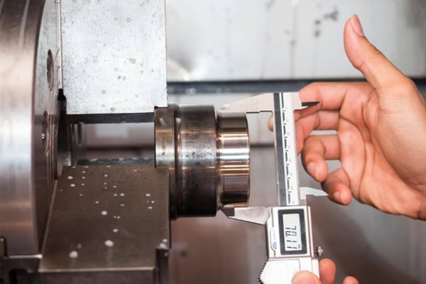
External diameter is one of the most common dimensions measured on CNC-turned components. Shafts, sleeves, and cylindrical parts often require precise external diameter inspection. Standard dimensions can be checked quickly with vernier calipers, while higher-precision external diameters are commonly measured with outside micrometers. During measurement, the measuring surfaces should be clean and free from chips, coolant, and burrs that could affect the reading.
- Use vernier calipers for quick dimensional checks
- Use outside micrometers for high-precision measurements
- Check multiple axial positions
- Check different circumferential positions
- Remove burrs and cutting fluid
- Compare results with drawing tolerances
- Record actual measurement data
For long shafts or precision components, measurements can be taken at different axial positions to determine whether the external diameter changes along the component. If significant differences are detected, the manufacturer should check tool wear, machine positioning accuracy, and cutting parameters.
Internal Diameter and Bore Inspection
Internal dimensions directly affect the assembly performance of bearings, pins, seals, and other mating components. Depending on bore size and accuracy requirements, internal diameters can be measured using inside micrometers, dial bore gauges, digital bore gauges, or dedicated plug gauges. During measurement, the instrument should be properly aligned with the bore axis, and measurements should be taken in different directions to evaluate both bore size and roundness.
- Check the actual bore diameter
- Measure different positions along the bore
- Check dimensions in different directions
- Determine whether the bore is uniform
- Inspect the bore wall for visible defects
- Compare measurements with mating tolerances
For deep-hole components, the effective measuring depth of the instrument must also be considered. Measuring only the entrance of a deep bore may not accurately represent the entire hole. Precision deep-hole machining therefore often requires specialized measuring equipment.
Length and Step-Dimension Inspection
Axial lengths, step heights, and end-face positions can affect component assembly and functional relationships. Length dimensions can generally be measured using vernier calipers, height gauges, or dedicated gauges. For precision step structures, dial indicators and precision measuring platforms can also be used.
Measurements should be referenced to the designated datum on the engineering drawing. Using inconsistent reference surfaces can produce misleading dimensional results. For components with several steps, each dimension should be checked according to the machining datum to ensure that every feature meets the specified requirements.
CNC Turning Geometric Tolerance Inspection Methods
A component meeting dimensional requirements does not necessarily mean that it is fully qualified. For precision mechanical components, geometric characteristics such as roundness, cylindricity, concentricity, axial runout, and radial runout are also important. For example, a shaft may meet its specified external diameter while still having excessive roundness or concentricity error. Such a component may cause vibration, uneven wear, or unstable rotation after assembly. Geometric inspection requires more specialized measuring equipment and strict control of workpiece positioning and measurement datums. For precision CNC turning, geometric inspection provides additional information about machine accuracy and process stability.
Roundness Inspection
Roundness inspection determines the deviation between the actual circular profile of a component and an ideal circle. Standard dimensional tools only measure size in one or several directions and cannot fully describe roundness characteristics. For precision components, a roundness measuring machine can rotate the workpiece and record profile variations before calculating the roundness error.
Roundness inspection is important for shafts, bushings, precision rotational components, and high-speed rotating parts. Poor roundness can create periodic vibration during high-speed operation and may affect equipment stability and service life.
Concentricity Inspection
Concentricity inspection evaluates whether the center axes of different cylindrical features remain properly aligned. For components containing multiple steps, journals, and bores, concentricity has a direct influence on assembly accuracy and rotational performance.
- Check the relationship between multiple shaft journals
- Check the center relationship between internal bores and external diameters
- Check concentricity between different stepped sections
- Reduce assembly eccentricity
- Minimize rotational vibration
- Improve component operating stability
When inspecting concentricity, an appropriate reference surface must be selected and the workpiece must remain securely positioned. High-precision components may require coordinate measuring machines or specialized roundness inspection equipment.
Runout Inspection
Radial runout and axial runout are common geometric inspection items for CNC-turned components. During measurement, the component is generally mounted on a precision fixture or rotational device while a dial indicator or digital indicator is used to measure movement. As the component rotates, the indicator variation represents the corresponding runout.
Runout inspection can help identify workholding errors, spindle accuracy problems, and component machining deviations. If runout exceeds the specified tolerance, the manufacturer should inspect the workpiece datum, chuck condition, spindle accuracy, and machining program.
CNC Turning Thread Inspection Methods
Threaded components are widely used in mechanical connections, hydraulic equipment, automotive components, and automation machinery. Thread inspection involves more than checking major diameter, minor diameter, and thread length. Pitch, thread profile, effective thread length, and mating performance may also need to be verified. Standard external threads can be checked with thread ring gauges, while internal threads can be inspected with thread plug gauges. Precision threads may require thread micrometers, the three-wire method, or dedicated thread measuring equipment.
Thread Ring Gauge and Plug Gauge Inspection
Thread ring gauges are commonly used for external thread inspection, while thread plug gauges are used for internal thread inspection. Go/no-go gauges provide a fast method for determining whether a thread meets specified mating requirements and are particularly useful in batch CNC turning production.
- Check thread mating condition
- Identify abnormal thread profiles
- Check effective thread length
- Quickly identify out-of-tolerance components
- Suitable for batch production
- Improve inspection efficiency
Thread gauges should be kept clean during inspection. Chips or contamination can interfere with the engagement condition and produce incorrect results. Gauges themselves should also be calibrated according to an established schedule.
Thread Pitch and Profile Inspection
High-precision threads require accurate verification of pitch and thread profile. Incorrect pitch can prevent proper engagement, while an abnormal profile can affect connection strength and sealing performance. Suitable thread measuring tools should be selected according to the applicable thread standard and component requirements.
Precision threads also require attention to tool wear and machining parameters. If thread quality gradually deteriorates during batch production, the cause may be related to tool wear or synchronization errors between the spindle and feed system. Timely process adjustment can prevent further defective production.
CNC Turning Surface Roughness Inspection Methods
Surface quality influences friction, sealing, wear resistance, and assembly performance. External cylindrical surfaces, internal bores, end faces, and grooves produced by CNC turning normally show machining marks, and their surface roughness must be checked according to component specifications. Visual inspection can identify obvious scratches, dents, and burrs but cannot accurately determine microscopic surface roughness. Precision components therefore require a surface roughness tester.
Surface Roughness Tester Inspection
A surface roughness tester uses a probe that travels across the machined surface to collect microscopic profile variations and calculate corresponding roughness parameters. The inspection location should be representative of the actual surface condition, and the measurement direction should be selected according to the turning pattern.
- Inspect external cylindrical surfaces
- Inspect internal bore surfaces
- Check end-face quality
- Inspect sealing surfaces
- Check precision mating surfaces
- Compare results with specified roughness requirements
During measurement, the probe should be protected from chips, oil, and burrs. For critical surfaces, measurements should be taken at consistent positions and in consistent directions to improve data comparability.
Visual and Surface Defect Inspection
In addition to numerical roughness values, components should be checked for visible machining defects. Common defects include burrs, scratches, dents, chatter marks, thermal damage, built-up-edge marks, and incomplete machining. For sealing components, precision shafts, and appearance-sensitive parts, surface defects may directly affect final performance.
Visual inspection can serve as a basic inspection method. For small or difficult-to-see defects, magnifying glasses, microscopes, or machine vision systems can provide additional inspection capability.
First-Piece, In-Process, and Final CNC Turning Inspection
Quality inspection should not be concentrated only after machining has been completed. It should be integrated into the production process. First-piece inspection confirms whether the program and machine setup are correct. In-process inspection monitors dimensional changes during batch production. Final inspection confirms whether completed components meet all technical and customer requirements. These inspection stages work together to reduce production risks.
First-Piece Inspection
First-piece inspection is an important step before batch production begins. Operators should inspect critical dimensions, geometric tolerances, threads, and surface quality according to engineering drawings and process requirements while confirming that tool compensation, work coordinates, and machining programs are correct.
- Check critical external diameters
- Check internal bore dimensions
- Check lengths and steps
- Inspect threads
- Check runout
- Inspect surface quality
- Confirm critical tolerances
Continuous production can begin after the first component has been confirmed as qualified. This significantly reduces the risk of large-scale scrap caused by programming or setup errors.
In-Process Inspection
In-process inspection monitors dimensional and quality changes during production. Cutting tools gradually wear during continuous machining, and component dimensions may slowly shift. Regular sampling can identify these changes and allow tool compensation to be adjusted.
Inspection frequency should be determined according to component accuracy, material, production volume, and tool life. High-precision components and expensive materials generally require stricter process monitoring.
Final Inspection
Final inspection confirms whether finished components comply with engineering drawings, process documents, and customer quality requirements. In addition to critical dimensions, inspectors may need to check threads, surface roughness, geometric tolerances, and visual quality according to the component specifications.
For important precision components, complete inspection records can be maintained, including component identification numbers, inspection items, actual measurement results, inspection times, and inspector information. These records support quality traceability and future process improvement.
CNC Turning Inspection Environment and Measuring Tool Management
Inspection results depend not only on measuring equipment but also on temperature, cleanliness, measuring-tool accuracy, and operator technique. Metal components expand or contract as temperature changes, so high-precision inspection requires a relatively stable environment. Before measurement, coolant, chips, burrs, and other contaminants should be removed from the workpiece. Measuring tools should also be checked to ensure that they are within their valid calibration period. Common tools such as micrometers, dial indicators, calipers, and gauges require regular calibration and proper maintenance.

Control Inspection Temperature
Temperature has a significant influence on high-precision dimensional inspection. Components that have just undergone high-speed turning may be warmer than the inspection environment. Measuring them immediately can produce dimensional deviations. Precision inspection generally requires the component to reach a stable temperature before measurement.
- Maintain stable inspection conditions
- Avoid measuring hot components immediately
- Control the temperature difference between the workpiece and measuring tool
- Reduce temperature-related measurement errors
- Allow precision components sufficient temperature stabilization time
Proper temperature control improves the reliability of high-precision dimensional data.
Strengthen Measuring Tool Calibration Management
Measuring tools can wear or lose accuracy after prolonged use. Even when the operator uses the correct measurement procedure, inaccurate equipment can produce unreliable results. Manufacturers should establish calibration schedules according to measuring tool type, usage frequency, and accuracy class.
Common measuring tools should be kept clean and stored properly to prevent impact damage, corrosion, and abnormal loads. High-precision inspection equipment should also have detailed status records and calibration documentation.
CNC Turning Inspection Technology Improves Machining Quality
CNC turning inspection is not limited to measuring a few dimensions. It combines dimensional inspection, geometric tolerance inspection, thread inspection, surface quality inspection, first-piece inspection, in-process monitoring, and final inspection to determine component quality. External diameters and lengths can be quickly checked with calipers and micrometers. Internal bores can be verified with internal measuring instruments. Threads can be checked using ring gauges and plug gauges. Roundness, concentricity, and runout can be inspected using dial indicators, roundness testers, or coordinate measuring machines according to the required accuracy. Surface roughness can be measured with dedicated roughness testers to obtain more reliable data. In batch CNC turning production, first-piece inspection reduces programming and setup errors, in-process inspection identifies dimensional changes caused by tool wear, and final inspection confirms that finished components meet delivery requirements. At the same time, inspection temperature, workpiece condition, measuring-tool calibration, and standardized operating procedures need to be controlled consistently. Establishing a systematic inspection process allows manufacturers to accurately monitor component quality, reduce batch defects and rework, and improve dimensional consistency, production stability, and product reliability in CNC turning operations.
















