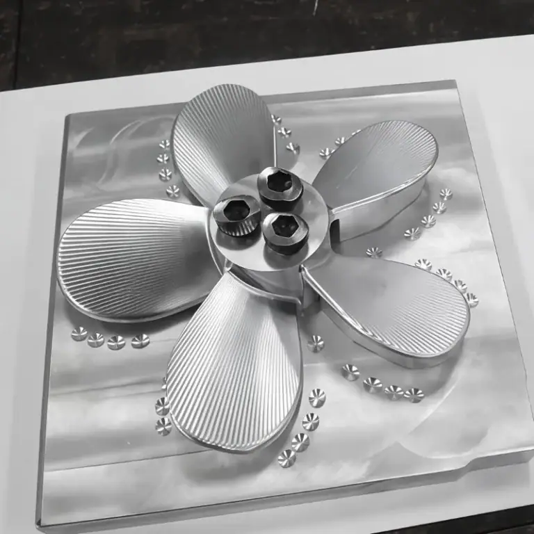
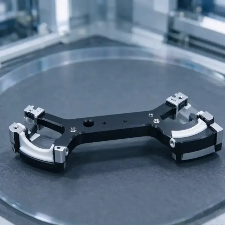
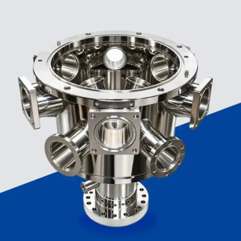
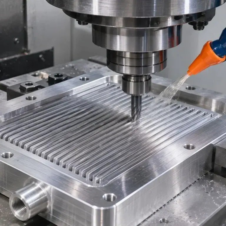
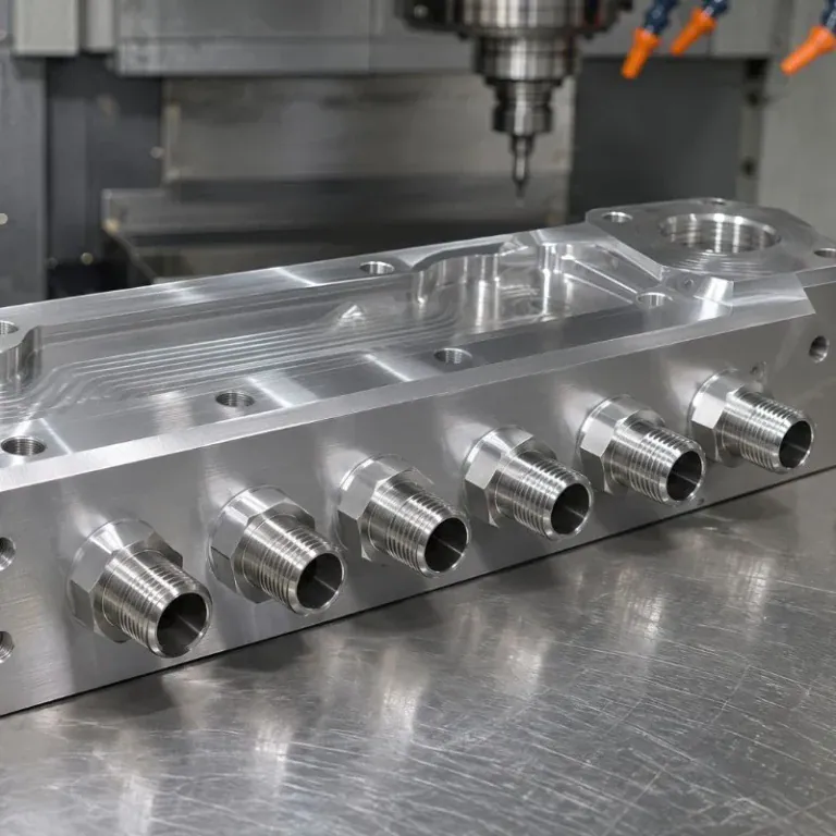
Surface roughness in CNC turning is a critical indicator affecting the appearance, assembly precision, and functional performance of precision components. In the manufacturing of automotive parts, automation equipment, industrial connectors, precision shafts, and various mechanical accessories, surface quality directly influences the fit between components, friction characteristics, and the effectiveness of subsequent surface treatments. For businesses requiring custom CNC-turned parts, controlling surface roughness helps ensure product consistency, reduces the need for rework, and meets the technical specifications required for diverse applications. By carefully selecting cutting tools, machining parameters, materials, and cooling methods, manufacturers can improve metal surface quality while balancing production efficiency and costs. Understanding the factors that influence surface roughness in CNC turning enables manufacturers to optimize their machining processes and assists procurement professionals in defining precise quality requirements for parts.
Fundamentals of Surface Roughness in CNC Turning
Surface roughness in CNC turning describes the microscopic irregularities—the peaks and valleys—on a machined surface. Even when a metal surface appears perfectly smooth to the naked eye, it may still contain subtle tool marks, undulations, or irregular peaks and valleys. Roughness requirements are typically determined based on the part’s intended use, how it fits with other components, and the specifications outlined in engineering drawings. Since different parts have varying surface quality requirements, setting appropriate standards helps avoid unnecessary costs associated with excessive finishing.
The Difference Between Ra and Rz
Ra (arithmetic mean deviation of the profile) is a common parameter used to describe the average deviation of a measured profile from its mean line. Rz, on the other hand, characterizes the height of the profile’s peaks and valleys; the specific calculation method depends on the measurement standard being applied. While both parameters help manufacturers evaluate the quality of a machined surface, they are not directly interchangeable.
- Ra Surface Roughness: Frequently used in mechanical drawings, precision machining, and quality inspection, Ra provides an assessment of the overall microscopic irregularities of a machined surface. A lower value generally indicates smaller deviations, though the actual quality should always be evaluated in the context of specific measurement conditions and the functional requirements of the part.
- Rz Surface Roughness: Focuses more specifically on the height of the profile’s peaks and valleys. It serves as a useful supplementary metric for assessing the impact of localized, larger irregularities on the surface of a part.
- Selecting Roughness Standards: Designers should determine inspection parameters based on a part’s operating environment, friction conditions, sealing requirements, and assembly method, rather than judging machining quality solely by its visual appearance.
Once roughness parameters are clearly defined, the machining supplier can establish appropriate tooling choices, finishing processes, and inspection protocols, ensuring that quality acceptance is conducted according to a unified standard.
Roughness Requirements for Different Parts
CNC-turned parts have varying surface quality requirements depending on their intended use. For instance, standard support shafts, locating pins, and mechanical connectors may be produced using conventional turning processes, whereas hydraulic components, precision-fit shafts, and parts subject to relative motion typically require more stringent surface quality control.
Precision Shaft Components: The roughness of journals and mating surfaces affects assembly clearance, contact conditions, and operational stability; therefore, the finishing process must be selected based on specific fit requirements.
- Hydraulic and Pneumatic Components: Certain sealing/mating surfaces require strict roughness control to prevent surface defects from compromising sealing performance. Specific requirements should be determined based on the sealing structure and product specifications.
- Aesthetic/Visible Components: For exposed metal surfaces, considerations must include the uniformity of tool marks, surface gloss, and requirements for subsequent treatments such as anodizing, electroplating, or painting.
- Batch-Produced Mechanical Parts: Consistent surface quality must be maintained across an entire production batch, ensuring that variations—such as those caused by tool wear or changes in equipment status—are minimized.
Clearly specifying roughness requirements for critical surfaces on engineering drawings enables suppliers to accurately assess machining complexity, eliminate redundant processes, and improve the consistency of delivered parts.
Factors Affecting Surface Roughness in CNC Turning
The surface quality of CNC-turned parts is influenced by factors including tool geometry, cutting parameters, material properties, machine tool rigidity, and the machining environment. Even when using the same CNC lathe, different materials or part geometries can yield different surface results. Understanding these factors helps in rapidly identifying the root causes of quality issues and developing more effective machining strategies.

Tool Material and Nose Radius
The cutting tool comes into direct contact with the workpiece to remove material; the condition of its cutting edge and its geometric configuration dictate the profile formed on the machined surface. Tool wear, edge chipping, or the formation of a built-up edge (BUE) can lead to surface scratches, increased roughness, and dimensional fluctuations. Selecting an insert suitable for the workpiece material and maintaining the tool in good condition are essential measures for improving surface quality.
- Tool Material: Carbide tools are widely used for turning steel, aluminum alloys, and various engineering materials. The appropriate insert grade should be selected based on material hardness, cutting speed, and specific machining requirements.
- Nose Radius: An optimal nose radius helps improve the surface profile; however, an excessively large radius may increase cutting forces, potentially causing vibration or deformation in slender shafts or thin-walled components.
- Cutting Edge Condition: A sharp, intact cutting edge helps minimize material tearing and surface damage. If significant wear, chipping, or abnormal tool marks appear, the insert should be inspected and replaced promptly.
- Tool Setup: Factors such as the tool’s center height, clamping rigidity, and overhang length all influence cutting stability. Proper tool setup reduces vibration and enhances the consistency of the machined surface.
Selecting a cutting tool requires balancing surface quality, machining efficiency, and tool life; the suitability of a tool should not be judged based on a single parameter alone.
Cutting Speed and Feed Rate
Cutting speed and feed rate are critical process parameters that affect surface roughness in CNC turning. Inappropriate parameter settings can result in visible tool marks, the formation of a built-up edge, elevated cutting temperatures, or machine tool vibration. Finishing operations generally require a more stable cutting process to meet dimensional tolerances and surface quality specifications.
- Cutting Speed: An appropriate cutting speed helps optimize the cutting process, while excessively high speeds may increase thermal load and accelerate tool wear. Specific settings should be determined by considering the workpiece material, the tool grade, and the capabilities of the machine tool.
- Feed Rate: The feed rate influences the spacing between adjacent tool marks and is a key factor in controlling the surface roughness of turned parts. During finishing operations, the feed rate can be adjusted based on tool specifications and the rigidity of the workpiece; the results should then be verified through trial cuts.
- Depth of Cut: An appropriate depth of cut helps maintain a stable machining process. The allowance for finishing should be carefully determined—excessive allowance increases the cutting load, while insufficient allowance may prevent the tool from cutting stably.
- Parameter Coordination: Cutting speed, feed rate, and depth of cut must be adjusted in coordination with one another. Changing a single parameter in isolation may not yield the desired outcome; therefore, adjustments should be validated by considering the condition of the cutting tool, the material of the workpiece, and data from surface inspections.
By setting cutting parameters appropriately, one can minimize irregular tool marks on the machined surface, enhance production efficiency, and reduce the time costs associated with repeated process adjustments.
Methods for Improving Surface Quality in CNC Turning
Improving the surface quality of turned parts requires addressing several factors, including cutting tools, machining parameters, equipment condition, and cooling/chip evacuation. For precision custom parts, it is advisable to perform trial cuts before full-scale production to ensure that dimensions and surface roughness meet the specifications outlined in the technical drawings, thereby establishing a stable and reliable machining process.
Optimizing the Finishing Process
Finishing operations are typically employed to achieve final dimensional and surface quality requirements. Properly sequencing roughing and finishing stages ensures that the high cutting loads generated during roughing do not adversely affect the final surface. For parts with stringent dimensional accuracy requirements, it is also necessary to control deformation caused by clamping and thermal fluctuations during the machining process.
- Appropriate Allocation of Machining Allowance: The roughing stage should efficiently remove excess material while leaving an adequate allowance for finishing. An excessive allowance may increase the cutting load during the final pass, while an insufficient allowance can lead to unstable cutting conditions.
- Ensuring Stable Clamping: Insufficient clamping force may cause the workpiece to shift, whereas excessive force can lead to the deformation of thin-walled components. The clamping method should be selected based on the specific shape and material of the workpiece.
- Minimize unnecessary tool changes: Strategically sequencing machining operations helps reduce errors caused by repositioning and ensures the continuity of critical machined surfaces.
- Implement trial cuts for verification: Perform trial cuts on critical surfaces, then inspect dimensions, surface roughness, and tool marks. Adjust parameters based on the inspection results before proceeding to full-scale production.
A well-planned manufacturing process not only improves surface quality but also enhances machining efficiency and the consistency of batch deliveries.
Controlling Vibration and Chips
Machining vibration can create ripples or periodic tool marks on the workpiece surface; in severe cases, it may lead to dimensional inaccuracies and tool damage. Vibration often stems from excessive workpiece overhang, insufficient tool rigidity, unstable clamping, or inappropriate cutting parameters. Addressing these issues promptly helps improve surface quality.
During machining, minimize unnecessary tool overhang, and select appropriate chucks, soft jaws, or auxiliary supports based on the part’s geometry. For slender shafts, consider using a tailstock or other suitable support methods to increase workpiece rigidity. For thin-walled parts, carefully manage clamping forces and cutting loads to prevent deformation during the machining process.
Chip management is equally critical. If chips become trapped between the tool and the workpiece, they can scratch surfaces that have already been machined. Utilizing effective chip-breaking geometries, optimizing cutting parameters, and ensuring an adequate supply of coolant can improve chip evacuation. Additionally, production personnel should regularly clear the machining area to prevent chip accumulation from compromising process stability.
Controlling Surface Roughness Across Different Materials
A material’s hardness, toughness, thermal conductivity, and chip-formation characteristics all influence the surface quality of turned parts. Selecting the right tools and cutting parameters for a specific material helps mitigate issues such as burrs, built-up edges (BUE), and surface tearing. For custom CNC machining projects, the material grade and final surface requirements should be confirmed during the quotation and process evaluation stages.

Aluminum Alloys and Stainless Steel
Aluminum alloys offer excellent machinability and are frequently used for lightweight mechanical components, connectors, and parts for automation equipment. During machining, attention must be paid to issues such as chip adhesion, burr formation, and the buildup of material on the tool surface. Using sharp, appropriate cutting tools, maintaining stable cutting conditions, and ensuring efficient chip evacuation will help achieve a uniform machined surface.
The machinability of stainless steel varies by grade; some grades are prone to work hardening, and careful control of cutting heat and tool wear is essential. Selecting inserts designed for stainless steel, maintaining a consistent feed rate, and employing effective cooling methods can help minimize surface tearing and irregular tool marks. For parts requiring strict surface roughness control, optimal parameters should be determined through trial cuts rather than by simply applying settings used for other materials.
Carbon Steel and Engineering Plastics
Carbon steel is widely used for components such as shafts, fasteners, and industrial machinery parts. Its surface quality is influenced by material hardness, tool wear, cutting parameters, and the rigidity of the machine tool. For precision-fit surfaces, a stable finishing process should be established, with surface roughness and dimensions verified against the requirements specified in the engineering drawings.
Engineering plastics can also be processed via CNC turning; however, they differ from metals in terms of thermal expansion, rigidity, and chip characteristics. Excessive cutting temperatures can lead to localized softening, deformation, or a degradation in surface quality. When machining plastics, it is important to select tools suitable for the specific material, avoid excessive cutting loads, and carefully control the clamping force applied to the workpiece. For plastic parts requiring high dimensional stability, factors such as post-machining thermal recovery and the measurement environment should be considered to minimize the impact of thermal fluctuations on inspection results.
Surface Quality Inspection and Procurement Recommendations for CNC-Turned Parts
Surface roughness must be verified using appropriate inspection methods; it cannot be reliably assessed through visual observation or touch alone. For precision mechanical components, inspection results must align with the engineering drawings, technical agreements, and the intended application of the product. A robust quality inspection process enables manufacturers to identify machining issues promptly and provides a reliable basis for batch delivery.
Selecting an Appropriate Method for Measuring Surface Roughness
A surface roughness tester (profilometer) can be used to measure profile parameters within a specified area. During measurement, it is necessary to select the appropriate probe, measurement direction, and sampling conditions based on the part’s geometry, while configuring relevant parameters in accordance with applicable standards. For cylindrical turned surfaces, measurement locations should be determined based on specific inspection requirements; relying on a single measurement point to judge the acceptability of an entire component should be avoided.
Beyond surface roughness, critical parts may also require inspection for diameter, roundness, cylindricity, and surface defects. For orders with strict acceptance criteria, it is essential to define the inspection parameters, sampling ratios, and reporting requirements in advance, ensuring that both the supplier and the purchaser adhere to the same acceptance standards.
Selecting a Reliable CNC Machining Supplier
When sourcing custom CNC-turned parts, evaluate a supplier’s equipment capabilities, experience with specific materials, process control, and quality inspection procedures. A capable supplier should not only meet the dimensional tolerances specified in the technical drawings but also demonstrate the ability to consistently control surface roughness. For parts involving precision fits, sealing requirements, or subsequent surface treatments, communicating the requirements for critical surfaces well in advance is particularly important.
When requesting a quote, provide comprehensive documentation, including 2D engineering drawings, 3D models, material grades, surface roughness specifications, tolerances, surface treatment requirements, and order quantities. Clear technical data enables suppliers to accurately assess manufacturing complexity, select appropriate tooling and processes, and establish a realistic delivery schedule.
By establishing appropriate surface roughness standards, maintaining stable manufacturing processes, and implementing rigorous quality inspection, companies can enhance the surface consistency of CNC-turned parts, minimize rework and scrap, and obtain precision-machined components that better meet the requirements of their intended applications.