A metal part that looks simple on the outside often goes through several machining and inspection stages before it becomes a finished product that meets engineering requirements. In CNC metal machining, dimensions, geometry, surface roughness, and tolerances all need to be carefully controlled.
The exact machining process varies depending on the material, part geometry, and application. However, from raw material preparation to final delivery, the process generally includes design review, material preparation, rough machining, finishing, surface treatment, quality inspection, and packaging.
Get 20% offf
Your First Order
Need custom metal and plastic parts?
Step 1: Review the Drawings and Machining Requirements
Check Part Geometry and Dimensions
Before machining begins, engineers first review the 3D model, 2D engineering drawings, and technical requirements. Important details include part dimensions, hole locations, threads, chamfers, fillets, and critical tolerances.
For complex parts, engineers also need to determine whether the component is better suited to 3-axis, 4-axis, or 5-axis CNC machining.
Determine the Material and Machining Process
The appropriate metal material is selected based on the part’s operating environment and performance requirements. Common options include aluminum alloys, carbon steel, stainless steel, copper, and titanium alloys.
Once the material is selected, engineers develop the machining process based on the part geometry. This includes determining the machining sequence, cutting tools, cutting parameters, and workholding method.
Step 2: Prepare the Metal Raw Stock
Select the Appropriate Material Size
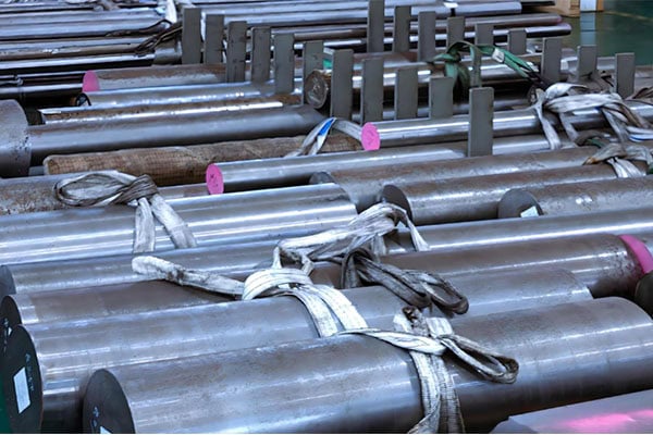
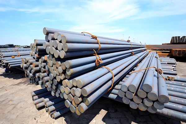
Metal part machining usually starts with raw stock. Depending on the application, the material may come in the form of sheet metal, bars, tubes, or other pre-formed stock.
The raw material dimensions should be selected based on the finished part size and required machining allowance. Stock that is too small may not provide enough material to produce the complete part, while excessive material allowance can increase waste and machining time.
Inspect Material Quality
Before machining, the material grade, specifications, and condition should be verified. For projects with strict material requirements, manufacturers may also need to review material certificates or perform additional inspections.
Step 3: CNC Rough Machining
Remove Excess Material Efficiently
The main purpose of rough machining is not to achieve final dimensions but to remove a large amount of excess material efficiently while leaving an appropriate allowance for finishing.
During this stage, relatively large depths of cut and suitable feed rates can be used to improve material removal efficiency.
Control Machining Deformation
Thin-walled parts, long shafts, and complex components require special attention during rough machining because they may be more susceptible to stress and deformation.
A suitable machining sequence and workholding method can help reduce deformation and create more stable conditions for subsequent finishing operations.
Step 4: CNC Finish Machining
Achieve Accurate Dimensions and Geometry
After rough machining, the part enters the finishing stage. The main goal is to remove the remaining material allowance and achieve the dimensions, tolerances, and geometry specified in the engineering drawings.
Finishing generally uses suitable cutting tools and more precise cutting parameters to achieve stable dimensional accuracy.
Improve Surface Quality
Finishing affects not only dimensional accuracy but also surface roughness. For cosmetic parts, mating components, and moving parts, surface quality may need to be controlled more carefully.
Depending on the requirements, finishing operations may include fine milling, precision turning, reaming, or other precision machining processes.
Step 5: Deburring and Cleaning
Remove Machining Burrs
Milling, turning, and drilling can leave burrs around part edges and hole openings. Burrs can affect appearance, assembly, and operating safety.
Depending on the part requirements, manufacturers may use manual deburring, mechanical deburring, or chamfering to remove them.
Remove Cutting Fluid and Metal Chips
After machining, cutting fluids, oil, and metal chips should be removed from the part surface. Proper cleaning ensures that the components are ready for inspection and any subsequent surface treatment.
Step 6: Surface Treatment
Select the Right Surface Finish
Some metal parts require additional surface treatment after CNC machining. For example, aluminum alloys can undergo anodizing, steel can be plated, blackened, or painted, while stainless steel may be passivated or polished.
Surface treatments can improve appearance, corrosion resistance, wear resistance, and other surface properties.
Consider Dimensional Changes During Surface Treatment
Some surface finishing processes can slightly affect part dimensions. For precision mating areas, these potential dimensional changes should therefore be considered during both the design and machining stages.
Step 7: Quality Inspection
Check Dimensions and Tolerances
After machining is complete, finished parts are inspected according to the engineering drawings. Common inspection tools include calipers, micrometers, height gauges, and coordinate measuring machines (CMMs).
For precision components, a CMM can measure multiple dimensions and geometric features to verify whether the finished part meets the design requirements.
Inspect Appearance and Surface Quality
In addition to dimensional inspection, the part should be checked for visible scratches, burrs, deformation, machining marks, and surface treatment defects.
For batch production, sampling inspections and process quality control can also help maintain consistent quality between different production batches.
Step 8: Packaging and Delivery
Protect the Finished Parts
After passing inspection, the parts need to be packaged appropriately. Precision-machined or surface-treated components should be protected from impact, scratches, and corrosion during transportation.
Prepare Delivery Documents
Some CNC machining projects also require dimensional inspection reports, material certificates, surface treatment certificates, or other quality documentation.
The process of turning metal raw stock into a finished component is more than simply cutting material. It is a complete manufacturing process that can include drawing review, material preparation, rough machining, finish machining, deburring, surface treatment, quality inspection, packaging, and delivery.
The exact process may vary depending on the part, but every stage can affect the final product quality. A well-planned CNC machining process can improve production efficiency while providing better control over dimensional accuracy, surface quality, and manufacturing costs.
Author
Galen Director and Founder
Committed to ensuring we provide the best possible service in the manufacturing industry.
CNC machining programming connects a digital part design with the movements of a CNC machine. A well-built program defines where the cutting tool moves, which tools are used, how fast
Vertical and horizontal milling use the same basic cutting principle, but spindle orientation changes how the tool reaches the workpiece, clears chips, and handles different part geometries. This guide explains
Chamfer machining is the process of removing material from an edge, hole, or contour to create a controlled angled surface. In CNC manufacturing, chamfers are commonly used to remove sharp
Custom machining is used when a part cannot be sourced as a standard component or when its geometry, material, tolerance, or function must be tailored to a specific project. Instead
Undercut machining creates recessed, hidden, or back-facing features that a standard straight-shank cutter cannot reach from the primary machining direction. The main challenge is usually not removing the material, but
Semiconductor equipment depends on far more than electronics and process technology. Behind every wafer-handling system, test station, inspection tool, and process chamber is a network of precision-machined parts, structural components,
AI CNC machining combines traditional computer numerical control with artificial intelligence, machine learning, manufacturing data, sensors, and intelligent CAM software. Instead of replacing CNC technology, AI adds a decision-support layer
Robotic process automation is a software-based automation technology that uses digital bots to complete repetitive, rules-based tasks normally performed by people on computers. RPA bots can enter and transfer data,
Computer numerical control machining is an automated manufacturing process in which programmed computer instructions control machine tools to remove material and produce precise parts. CNC technology can control tool movement,
Semiconductor manufacturing is the process of turning high-purity semiconductor materials into functional chips through a sequence of wafer preparation, thin-film formation, photolithography, etching, doping, metallization, testing, dicing, packaging, and final
Semiconductors are materials whose electrical conductivity can be controlled between that of conductors and insulators. Silicon is the most widely used semiconductor material, but germanium, silicon carbide, gallium nitride, gallium
Boring machining is a precision cutting process used to enlarge and correct an existing hole. Unlike drilling, which creates the initial hole, boring improves diameter, roundness, straightness, alignment, and internal