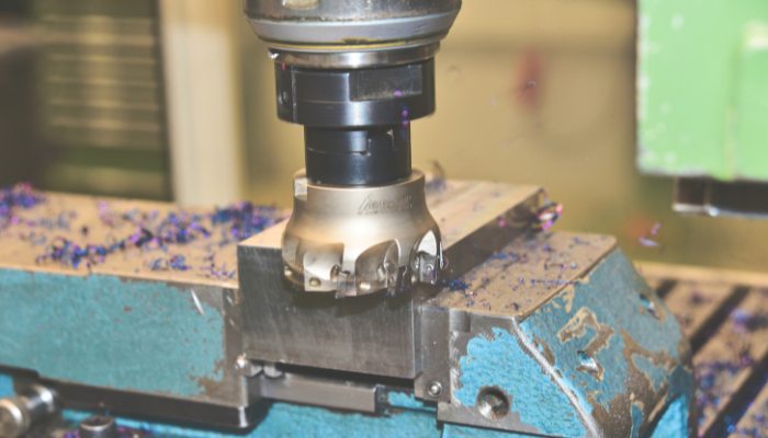
The requirements of product structure are met through different processing methods. Face milling is a commonly used processing technology. Reasonable use of this processing method can achieve a better processing surface.
What is Face Milling?
In short, face milling is a method of processing the surface of a product. It is suitable for processing large areas, planes or shapes.Precise manipulation of the milling tool path using the CNC enables fast and precise material removal, ensuring that the surface of the workpiece achieves the desired flatness and surface finish.
The technology efficiently cuts material to form precise flat surfaces by means of vertically placed milling cutters equipped with peripheral and bottom cutting edges.
The method optimizes material removal efficiency by finely controlling the tool motion path to achieve the desired surface accuracy and quality standards.
Equipment for Face Milling
1. CNC Milling Machine
CNC milling machines are often used to perform end milling operations. Their advantage lies in the ability to precisely adjust the position and movement of the tool, which is particularly important for tasks that require complex and detailed processing.
2. CNC Machining Center
Machining centers can provide more axes of motion, making face milling more versatile and precise, especially for complex parts that require multiple faces to be machined simultaneously.
3. Conventional Milling Machine
For simple face milling operations that do not require high precision, conventional milling machines are also capable.
Conventional Tools for Face Milling
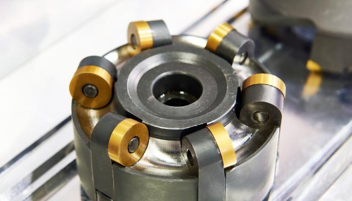
1. End Milling Cutter
Face milling cutters have multiple cutting edges and can be either fixed or interchangeable inserts. The diameter size of the face milling cutter can be selected according to the area of the workpiece and the machining requirements.
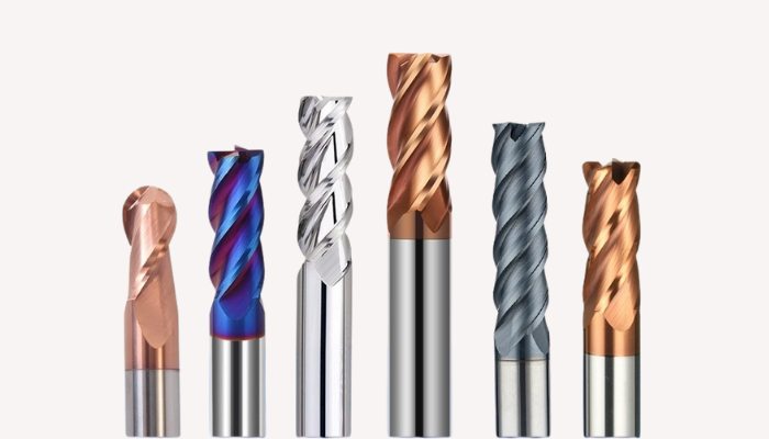
2. End Mill
General purpose milling cutters are usually used for slot milling and contour milling.They usually have fewer cutting edges but are suitable for a wide range of machining paths.
3. Round Nose Cutter
Round nose cutters (also known as ball end mills) are primarily used for surface machining and carving complex contours. They have a semi-circular tip, which is ideal for 3D contouring.
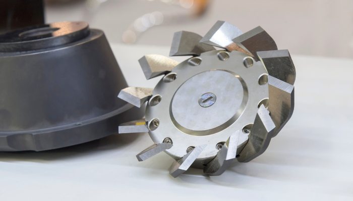
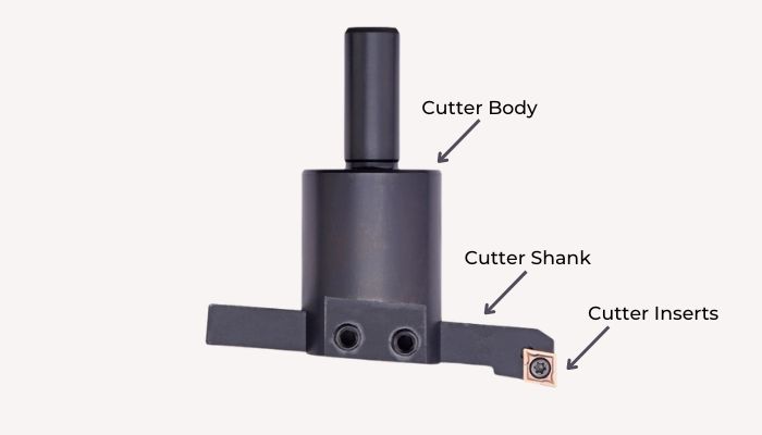
4. Fly Cutter
Fly cutters allow for a wide cutting surface, making them ideal for finishing operations where a large, smooth surface is desired. This wide swath also helps in achieving a better surface finish compared to other tools like end mills, especially over large areas.
Advantages of Face Milling
- High Efficiency: Face milling significantly enhances machining efficiency by engaging multiple cutting points in each rotation.
- Versatility: Equipped with various types of inserts, face milling cutters are capable of machining a broad array of material surfaces.
- Superior Surface Quality: The minimal vibration produced during face milling ensures high dimensional accuracy and excellent surface finishes.
- Quick tool change: The face milling cutter design supports quick insert change, which reduces machine downtime and increases productivity.
- Cost-effective: Replaceable blades for longer tool life and more economical tool costs.
Disadvantages of Face Milling
- Higher initial costs: High-quality end mills and CNC milling machines are a large investment and can be a significant expense for smaller manufacturers.
- High requirements for operating skills: CNC machine operation is relatively simplified, but the programming and operation of end milling still requires specialized training, and operators need to have a certain level of skills.
- Tool wear: Although inserts are replaceable, when machining hard materials, tools wear faster and require frequent replacement, which can increase production costs.
- Limitations on machining size: The size of the face milling cutter limits the minimum size and complexity of the machining.
How does an Face Milling Operation Work?
The face milling process involves several steps to ensure accuracy and efficiency. There are routinely 8 operational processes:
- Cleaning of Machine Processing Platforms
Cleaning the machine is a very important preparation to ensure that there are no impurities or swarf to affect the machining quality. Ensuring that the machine operates properly and that the machining platform is clean and tidy helps to improve machining accuracy and extend the life of the machine.
- Preparation of Milling Tools and Fixtures
Selection of suitable tools and fixtures is based on the requirements of the machining program. The tool must be selected according to the type of material and the expected cutting load, while the fixture needs to be able to hold the workpiece reliably.
- Fixed Workpieces
Use fixtures to secure the workpiece to the milling machine table. It must be ensured that the workpiece is accurately positioned and securely fastened to prevent movement during machining.
- Setting Cutting Parameters
Set processing parameters according to product structure and material type.These parameters directly affect machining efficiency, surface quality and tool life.
- CNC Milling
Starts the milling machine and executes the previously set program. Monitor the machining process to ensure that the tool is moving in the intended path. Note any abnormal sounds or vibrations of the machine and make timely adjustments to avoid damage to the workpiece or tool.
- First Sample Testing
After machining the first workpiece, the first piece inspection is carried out to ensure that the machining quality meets the technical requirements. Check the key indexes such as size, surface roughness, etc. If there is any deviation, the machining parameters need to be adjusted.
- Repeat Processing
Once the first piece passes quality inspection, the same machining program can be continued to produce more of the same piece. Continue to monitor the production process to ensure that all pieces meet the same quality standards.
Different Approach for Face Milling
Mechanical engineers choose different end milling methods depending on the requirements.Below are some of the main methods of face milling:
- General Face Milling
This is the most basic form of face milling, using standard face milling cutters for flat surface machining. Conventional face milling is usually used for large areas of material removal and is suitable for roughing and semi-finishing.
- High-Feed Milling
In this type of machining, specially designed high-feed milling cutters are used, which are capable of machining at very high feed rates with a small depth of cut. High-feed face milling is mainly used to remove large amounts of material in a short period of time with great efficiency.
- Heavy Duty Milling
Used for heavy workpieces that require extensive material removal. This method uses a powerful milling cutter and a large depth of cut to quickly remove thicker layers of material and is often used for roughing.
- Precision Face Milling (PFM)
Precision face milling focuses on high accuracy and good surface finish. This approach typically uses precision manufactured milling cutters and careful control of machining parameters and is suitable for finished products requiring high accuracy.
- Contour Milling
In contour face milling, end mills are used not only to generate flat surfaces but also to machine complex contours and shapes. This type of machining requires precise control of the path of the milling cutter to form the desired geometry.
- Form Milling
Special milling cutters are used to generate specific shapes and contours. These cutters are shaped to match the shape of the surface to be machined and are suitable for machining complex patterns and detailed designs.
- Trochoidal Milling
A dynamic milling technique that reduces heat buildup and tool wear by reducing the contact time between the tool and the workpiece through involute tool paths. This method is suitable for hard materials or applications that require long milling times.
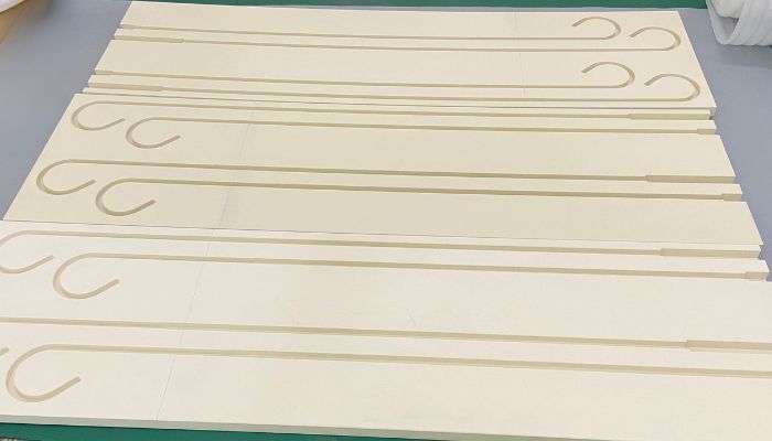
Different Materials for Face Milling
Mechanical engineers choose different end milling techniques and tools for different materials.Below are the characteristics of face milling for various materials:
1. Face Milling Aluminum
- Tool Material: Carbide or polycrystalline diamond (PCD) tools are recommended for their high wear resistance and ability to maintain sharpness.
- Cutting Speed: Aluminum is soft, allowing the use of higher cutting speeds, usually in the range of 600 to 3000 m/min.
- Feed Rate: Higher feed rates can be used to prevent the tool from generating too much heat and sticking to the material.
- Depth of Cut: Larger depths of cut are usually feasible.
- Coolant: Using the proper coolant can help prevent overheating in the cutting zone and improve cut quality.
2. Face Milling Stainless Steel
- Tool Material: Use carbide or cobalt chrome tools, as stainless steel is tough and easily work-hardened.
- Cutting Speed: Relatively low, usually in the range of 60 to 180 m/min to control the heat generated by machining.
- Feed Rate: Should be moderate to balance machining efficiency and avoid overheating.
- Depth of Cut: Smaller depths of cut help control heat and improve surface quality.
- Coolant: It is critical to use a proper cooling system to help reduce heat and prevent tool wear.
3. Face Milling Titanium
- Tool Material: Carbide tools with Titanium Aluminum Nitride (TiAlN) coating are recommended to resist high temperatures.
- Cutting Speeds: Low, usually in the range of 60 to 100 meters per minute, because of the poor thermal conductivity of titanium.
- Feed Rate: Lower feed rates help reduce heat generation.
- Depth of Cut: Shallower depths of cut help control cutting temperatures.
- Coolant: The use of coolant is extremely important in titanium machining to avoid burning of the material and to improve tool life.
4. Face Milling Steel
- Tool Material: Using carbide tools with coatings such as TiAlN can improve tool life.
- Cutting Speed: Adjusted according to the hardness of the steel, generally in the range of 200 to 300 meters per minute.
- Feed Rate: Medium to high, adjusted to the hardness of the steel and the specific operating conditions.
- Depth of Cut: Medium depth of cut is usually the most appropriate.
- Coolant: The use of coolant helps cutting performance and extends tool life.
5. Face Milling Plastic
- Tool Material: Uncoated carbide or PCD tools are recommended to minimize friction and prevent material melting.
- Cutting Speed: usually low to prevent deformation or damage to the material due to heat.
- Feed Rate: Lower feed rates help ensure cut quality and prevent tearing or pulling.
- Depth of Cut: should be moderate, too deep may lead to workpiece deformation or tool breakage.
- Coolant: Using the proper coolant or air purge can help control cutting temperatures and prevent static buildup in some cases.
Key Tips for Face Milling
To achieve the best results, it’s essential to use the right strategies and tools. Here are some practical tips to optimize your face milling operations.
- Choose the Right Cutter
Material Compatibility: Select a cutter that is suitable for the material you are machining. For example, carbide cutters are excellent for hard materials like steel and titanium, while high-speed steel (HSS) may be suitable for softer materials like aluminum. For example, carbide cutters are excellent for hard materials like steel and titanium, while high-speed steel (HSS) may be suitable for softer materials like aluminum.
Cutter Size: Use a cutter with a diameter that is appropriate for the job. Larger diameters can cover more area but might require more powerful machinery.
Insert Type: Consider using inserts that match your specific needs-coated inserts can increase tool life and performance when cutting Coated inserts can increase tool life and performance when cutting abrasive or very hard materials.
- Optimize Cutting Parameters
Cutting Speed: Determine the optimal cutting speed for your material. Harder materials generally require slower speeds to reduce wear on the cutter.
Feed Rate: Adjust the feed rate to achieve the desired surface finish and productivity. Higher feed rates can increase productivity but may reduce surface quality.
Depth of Cut: Use a conservative depth of cut to extend tool life, or increase it to improve material removal rates, depending on your priority.
- Use Suitable Tool Paths
Overlap: Ensure there is adequate overlap between passes to avoid leaving uncut strips on the workpiece.
Direction: Consider using climb milling (where the cutter rotates in the direction of the feed) for most materials to improve finish and extend tool life, except in cases where machine backlash is an issue. except in cases where machine backlash is an issue.
- Maintain Tool Stability
Tool Overhang: Minimize tool overhang from the spindle to reduce vibrations and improve cut quality.
Secure Clamping: Ensure that both the tool and workpiece are securely clamped to prevent any movement during milling.
- Manage Chips and Heat
Chip Evacuation: Use appropriate chip evacuation strategies such as compressed air or coolant systems to prevent chips from interfering with the cutting process. Cutting process.
Cooling: Apply coolant effectively, especially when machining materials that are prone to heating or when the tool is at risk of overheating. This will help in reducing tool wear and potential thermal deformation of the workpiece.
Conclusion
In summary, to achieve efficient and high quality end milling results, it is necessary to consider the material properties, tool performance, machining requirements and machining methods.Tirapid has a unique machining technology for end milling through continuous experience, and we can provide you with more optimized milling guide.


