
When machining plastic parts with CNC, “springback” is a relatively common dimensional abnormality, especially in thin-walled parts, long strip-shaped parts, deep-groove parts, narrow-edge structures, and engineering plastic components with high elasticity. Plastic machining springback refers to a situation in which the material undergoes a certain degree of deformation during cutting, clamping, or under load, and then partially returns to its original shape after the cutting force is removed, the fixture is released, or the part machining is completed. This ultimately causes a deviation between the actual dimensions and the values set in the machining program. For ordinary appearance parts, this change may not be easy to notice, but for plastic components such as bushings, seals, sliders, precision brackets, and positioning parts that require mating installation, springback may directly affect assembly dimensions.
Compared with metal materials, plastics generally exhibit more obvious elastic deformation. During CNC machining, the tool continuously applies cutting forces to the workpiece, and the material may undergo temporary bending or displacement when subjected to compression. If the clamping pressure is too high, the part may already be in a slightly deformed state during machining. After the tool completes cutting according to this state, releasing the fixture allows the part to return to its original shape, naturally causing changes in the final dimensions. Different plastics, such as POM, PA, PE, PEEK, PTFE, and ABS, have different levels of springback due to differences in hardness, elasticity, friction characteristics, and internal stress. Therefore, CNC plastic machining cannot be handled entirely according to conventional metal machining practices. The machining method needs to be arranged according to the material characteristics and part structure.
Why Are Plastic Parts Prone to Springback During CNC Machining?
Significant Elastic Deformation of the Material
Plastic deforms when subjected to external forces and may partially recover its shape after the external force is removed. During CNC milling and turning, the tool does not simply remove material; it also applies a certain amount of lateral and compressive force to the remaining workpiece. For thick plastic blocks, this change is generally not obvious. However, for thin-walled structures, long strip-shaped structures, or unsupported machining areas, cutting forces can more easily cause the workpiece to bend. When the tool leaves the machining area, the material partially returns to its original shape, which may result in dimensional deviations.
Clamping Pressure Changes the Machining Condition
Plastic parts need to be secured using fixtures, vises, clamping plates, or specialized tooling. If the clamping pressure is too high, the workpiece may undergo slight deformation before machining even begins. During machining, the tool cuts according to the deformed surface of the workpiece. After machining is completed, releasing the fixture allows the part to return to a condition close to its natural state, which may cause dimensional changes on the already machined surface. This is also a common reason why thin-walled plastic parts have “correct dimensions during machining but different dimensions after removal.”
Residual Stress Release Affects Dimensions
Plastic raw materials may develop internal stress during extrusion, injection molding, pressing, and other manufacturing processes. As CNC machining continuously removes material, the internal stress that was originally in a balanced state may gradually be released, causing the part to bend, twist, or change dimensions.
Thick plate machined into a thin-walled part: Removing a large amount of material makes stress release more likely.
Long strip-shaped parts: The release of internal stress may cause bending.
Ring-shaped parts: After the inner hole is machined, the dimensions of the outer diameter and inner hole may change.
Asymmetrical structures: Unequal amounts of material are removed from different areas, making local deformation more likely.
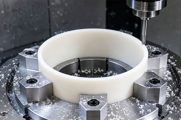
What Machining Conditions Can Increase Plastic Springback?
Plastic springback is not only related to the material itself. Part dimensions, structural shape, wall thickness distribution, and overall rigidity can also have significant effects. At the same time, tool sharpness, tool wear, tool geometry, and chip removal capability can directly change the forces applied to the workpiece during cutting. In addition, different machining methods can affect the stress and deformation state of plastic materials during machining to varying degrees, thereby further affecting the final springback behavior.
Excessive Cutting Force
If the tool removes too much material in a single pass, or if the feed rate and cutting depth are set improperly, the lateral force applied to the workpiece will increase. For thin-walled plastic parts, this cutting force may directly cause the workpiece to shift. During machining, if the workpiece visibly vibrates after the tool passes, or periodic machining marks appear on thin-walled areas, the cutting load should be checked to determine whether it is too high.
Insufficiently Sharp Tools
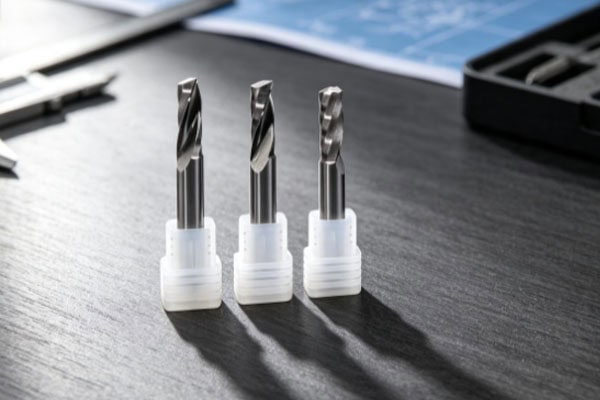
As a tool wears, its cutting edge becomes less capable of easily entering the material and is more likely to compress and rub against the plastic. This not only increases cutting heat but also increases the mechanical pressure applied to the workpiece. Using sharp tools suitable for plastic machining can reduce excessive compression of the material. For precision plastic parts, tool condition needs to be checked regularly rather than waiting until obvious burrs appear before replacing the tool.
Excessive Machining Allowance
Removing too much material in a single operation places a greater cutting load on the workpiece and may also cause internal stress to be released more quickly. When machining thick plastic plates into thin-walled structures, it is particularly important to avoid removing a large amount of material in a single operation. Rough machining and finishing are generally performed separately, with most of the material removed during rough machining while an appropriate allowance is retained for finishing. This can reduce the cutting force during final dimensional machining.
How Can CNC Plastic Part Springback Be Reduced?
Reducing springback does not mean completely eliminating material deformation. Instead, reasonable machining processes and optimization methods are used to minimize deformation caused by loading, clamping, or internal stress release during CNC machining, allowing the plastic to maintain higher dimensional stability after machining is completed and the part is removed from the fixture. This helps the final measured dimensions remain closer to the tolerance range and assembly accuracy requirements specified in the engineering drawings.
Properly Design the Clamping Method
For thin-walled, long strip-shaped, and irregular plastic parts, clamping should provide reliable fixation while avoiding excessive tightening. If necessary, additional support points can be added to provide sufficient support near the cutting area. For relatively thin plate-shaped parts, soft pads or dedicated support structures can also be used to reduce deformation caused by direct pressure from the fixture on the plastic surface.
Remove Material in Stages
For plastic parts requiring a large amount of material removal, rough machining, semi-finishing, and finishing can be used. The main purpose of rough machining is to remove excess material, while the finishing stage uses only a small cutting amount so that the final cutting operation is subjected to less force. For plastic materials with obvious internal stress, the part can also be allowed to rest appropriately after rough machining before finishing and dimensional inspection. The specific treatment method should be determined according to the material grade and part requirements.
Adjust Tools and Cutting Parameters
Tool selection needs to take the hardness, toughness, and machining characteristics of the plastic into consideration. Keeping the tool sharp can reduce cutting resistance. Machining parameters should not simply pursue high spindle speeds or high feed rates but should be adjusted according to the actual material and tool conditions. If the part has a thin-walled structure, the cutting depth can be appropriately reduced during finishing so that the tool completes the final dimensional machining under a lower load, thereby reducing the possibility of elastic deformation of the workpiece.
Frequently Asked Questions
Q: Why Are Plastic Part Dimensions Accurate During Machining but Change After Removal?
This situation is generally related to clamping deformation and internal stress in the material. During machining, the fixture may press the workpiece into a deformed state, and the tool completes cutting according to this condition. After the part is removed, the clamping force disappears and the material partially returns to its original shape, causing the final measured dimensions to differ from those during machining.
Q: Do All Plastics Experience Significant Springback?
No. Different plastics have different levels of elasticity, rigidity, and internal stress, so the degree of springback varies. POM generally has good dimensional stability, but thin-walled POM parts may still deform. Materials such as PA, PE, and PTFE may also exhibit relatively noticeable elastic deformation under certain structural conditions due to their inherent material characteristics.
Q: Can Increasing Clamping Pressure Solve Plastic Machining Springback?
It cannot be solved simply by increasing clamping force. Excessive clamping force may instead cause the plastic part to deform before machining begins. A more appropriate approach is to improve the support method, provide stable support in the machining area, and control the clamping pressure.
Conclusion
“Springback” during CNC plastic machining is essentially related to material elasticity, clamping deformation, cutting forces, and internal stress. Plastic parts may temporarily remain in a loaded state after being subjected to tools and fixtures during machining. When the cutting force or clamping pressure is removed, the material partially returns to its original shape, making dimensional changes more likely. This situation deserves particular attention for thin-walled parts, long strip-shaped parts, deep-groove parts, and irregular structural components. In actual production, reducing plastic springback cannot rely solely on modifying the CNC program. Suitable tools and machining parameters need to be selected according to the characteristics of the plastic material, while clamping positions should be properly arranged to avoid excessive pressure from the fixture on thin-walled areas. For parts requiring a large amount of material removal, staged machining can be used to reduce the cutting load, with an appropriate allowance retained after rough machining before completing the finishing operation.
For parts with high precision requirements, final dimensional inspection should also be performed after the part is removed from the fixture, because the loaded condition on the machine may not be the same as the part’s final free state. If the same batch of plastic parts shows dimensional inconsistencies, deformation in thin-walled areas, changes in inner hole dimensions, or bending after machining, the material batch, part structure, clamping pressure, tool wear, and machining allowance should be checked. Only by properly controlling these conditions can elastic deformation and dimensional springback during CNC plastic machining be reduced, allowing the machined parts to better meet engineering drawing requirements.
















