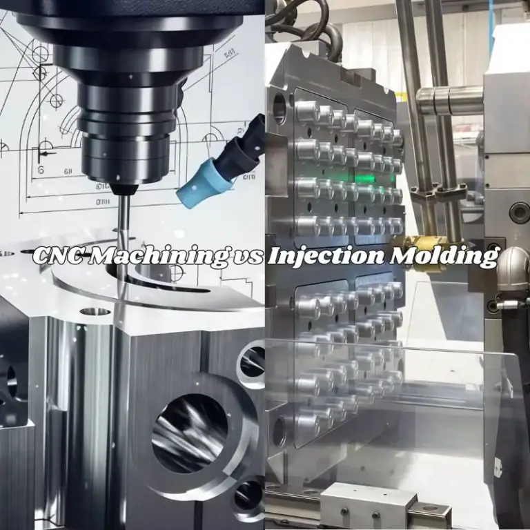
Vacuum components used in semiconductor equipment may not be very large, but their requirements are anything but simple. A vacuum flange, sealing seat, or connector may look like an ordinary metal part, but once installed in equipment, it has to handle sealing, assembly, and long-term operation. A slightly misplaced hole can make installation difficult; an improper sealing groove can cause leakage; deformation after machining may even prevent matched parts from fitting together. When customers look for a CNC machining supplier, their concerns are actually straightforward: Can the parts be made correctly from the drawings? Will installation go smoothly? And will the same quality be maintained throughout batch production?
What Problems Are Most Common When CNC Machining Semiconductor Vacuum Components?
Vacuum components are different from ordinary mechanical parts. Machining the outside shape is only part of the job. Flange faces, mounting holes, sealing grooves, internal cavities, and connection interfaces usually need to work together. A small deviation in one area can affect the entire assembly. For parts with complex structures, the machining process needs to consider tool access, vibration, chip removal, and possible deformation before CNC machining begins.
A Vacuum Sealing Surface Cannot Be Judged Only by How Smooth It Looks
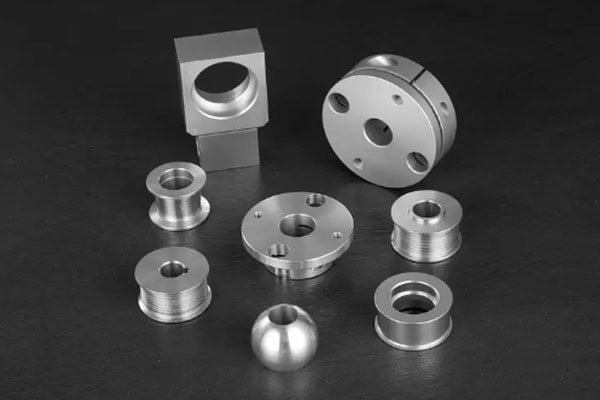
Vacuum flanges and sealing seats usually need to fit tightly with other components. Even a small surface problem can affect sealing performance. A surface may feel flat by hand, but precision machining cannot rely on touch or visual inspection alone. Flatness, surface roughness, sealing groove dimensions, and burrs around the groove all need to be checked with suitable inspection methods.
- The sealing groove needs to be machined correctly. If the groove is too deep, too shallow, too wide, or slightly out of position, the sealing element may not fit properly. Residues and small burrs also need to be removed after machining.
- The flange face needs to remain stable. Larger parts can deform slightly after a large amount of material is removed. The dimensions may look correct while the part is clamped on the machine, but change after the fixture is released.
- Critical surfaces cannot be judged only by appearance. Sealing areas, mounting areas, and non-functional surfaces may have different requirements. Any areas with specific roughness, cleanliness, or surface treatment requirements should be clearly identified in advance.
These details may look small, but they can directly affect equipment assembly. When the supplier identifies critical areas before machining, production and inspection can be more targeted, reducing unnecessary rework.
Deep Holes and Internal Structures Depend on Proper Tool Access
Some semiconductor vacuum components have complicated internal structures. They may look simple from the outside but contain deep holes, stepped holes, small passages, and narrow spaces. The deeper the tool goes, the easier it is for vibration to occur, while chips can also become harder to remove. If the tool approaches from the wrong direction, it may even interfere with areas that have already been machined. For these parts, the goal is not simply to achieve the required dimensions. The tool entry direction, machining sequence, and final machining operations all need to be planned in advance.
For customers, an important question is whether the supplier has experience with similar structures. If the machining team can identify potential problems with deep holes, internal cavities, or tool interference during drawing review, production can move much more smoothly instead of changing the process halfway through machining.
Thin-Wall Parts Are Particularly Sensitive to Deformation
Some vacuum components are designed with thin structures to fit limited spaces inside semiconductor equipment. These parts cannot be clamped too tightly during machining. A workpiece may appear dimensionally correct while clamped on the machine but spring back after being released. Heavy cutting can also release internal material stress and affect flatness and hole positions.
For thin-wall CNC machining, fixture support, machining sequence, and the amount of material removed at each stage all need to be carefully planned. Rough machining should not remove everything in one step. Leaving a suitable amount of material for finishing generally makes it easier to maintain stable dimensions.
Different Vacuum Component Materials Require Different Machining Approaches
Common materials for semiconductor vacuum components include aluminum alloys, stainless steel, and certain specialty metals. These materials behave quite differently during machining. Aluminum alloys are relatively easy to cut but can produce burrs and cause material to stick to the cutting tool. Stainless steel is harder to machine and places greater demands on tooling and cutting parameters. If the finished part will also receive anodizing, passivation, or another surface treatment, dimensional changes from the treatment need to be considered in advance. When requesting a quotation, customers should provide the material grade, quantity, and surface requirements clearly so the supplier can plan the machining process more accurately.
Aluminum Alloy: Easy to Machine, but Still Requires Careful Control
Aluminum alloys generally offer good machining efficiency, but semiconductor vacuum components often have stricter surface requirements than ordinary aluminum parts. Burrs or built-up material around sealing grooves, mounting holes, and internal cavities can make cleaning more difficult. Thin parts also require careful fixturing, or deformation may occur after machining.
- Tool condition needs to remain stable. Aluminum chips can stick to the cutting tool and affect the machined surface. This is particularly important around sealing areas, where problems should not be discovered only after an entire batch has been produced.
- Thin-wall areas should not be over-clamped. The workpiece needs to be securely held, but excessive clamping force can change its shape.
- Dimensional changes from surface treatment need to be considered early. Later treatment may affect hole diameters, mating areas, and surface conditions. It should not be considered only after all machining is finished.
In simple terms, aluminum is not difficult to machine. The key is keeping cutting speed, surface quality, and dimensional stability under control. This becomes especially important for batch orders. A process may work well at the beginning, but noticeable tool wear can create differences between finished parts later in the production run.
Stainless Steel: Slower Machining Is Fine, Dimensional Stability Matters More
Stainless steel puts more demands on cutting tools, and heat generated during machining can also be more significant. If a worn tool continues to be used, hole diameters, surface roughness, and other dimensions may gradually change. This may not be obvious when producing a single prototype, but the problem can become much more noticeable during batch production. A more stable approach is to monitor tool condition and inspect critical dimensions during production rather than waiting until the final operation to discover deviations.
| Material | Key Machining Concerns | What Customers Care About |
| Aluminum Alloy | Burrs, deformation, chip buildup | Sealing surfaces, hole positions, surface treatment |
| Stainless Steel | Tool wear, heat, chip removal | Dimensional stability, surface quality |
| Specialty Metals | Tool selection, cutting parameters | Precision, machining time, surface requirements |
How Can Rework Be Reduced From Prototype to Batch Production?
When customers develop semiconductor equipment, vacuum components are often not purchased just once. A few prototypes may be produced first, followed by small batches or ongoing production after validation. The real problem occurs when the prototype is successful but batch production later shows changes in hole positions, unstable sealing groove dimensions, or inconsistent surface quality. To reduce these problems, the prototype stage should not only confirm whether one part passes inspection. It should also verify whether the machining process can be reproduced consistently.
Confirm These Points Early During the Prototype Stage
After the prototype is completed, it should be tested for equipment fit while also recording key inspection data. This provides a clear reference for later production and avoids having to develop the process again for every batch.
- Check hole positions together. Mounting holes, locating holes, and threaded holes are usually related to each other. One hole meeting its individual tolerance does not necessarily mean the complete hole pattern will assemble correctly.
- Measure deep holes and internal cavities. Some problems cannot be seen from the outside, particularly depth, step positions, and internal connections.
- Inspect sealing areas separately. Flange faces, sealing grooves, and mating surfaces should have clearly defined requirements for flatness, roughness, and dimensions.
- Confirm leak-testing requirements in advance. If the equipment has specific vacuum sealing requirements, the test method and acceptance criteria should be confirmed before production to avoid making changes after batch production has already started.
Taking care of these points during the prototype stage can make later batch production much easier. Customers can also evaluate the supplier’s actual machining capability earlier instead of discovering problems after a large batch has already been completed.
Do Not Wait Until the End to Inspect Every Dimension
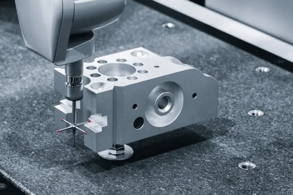
For complex vacuum components, inspecting everything only after machining is complete can lead to unnecessary work if a problem is found. A more practical approach is to inspect critical features after key machining operations. Check flatness after machining a reference surface, confirm hole positions after critical holes are completed, and inspect the width and depth of sealing grooves after machining. If a dimension starts to move away from the target, the machining process can be adjusted in time before the problem continues into later operations.
Vacuum Leak Testing Should Not Be Treated as an Optional Step
Vacuum components are ultimately installed in vacuum systems, so meeting drawing dimensions is only the basic requirement. If a part contains cavities, passages, or sealing interfaces, its leakage risk should be checked according to the equipment requirements. Vacuum leak testing or pressure testing can help identify problems in sealing areas, interfaces, and internal structures earlier. For batch production, keeping test records is also useful. If an abnormality appears in a later batch, previous inspection data can be reviewed quickly to help identify what changed.
| Inspection Item | What Is Checked | Main Purpose |
| Dimensional Inspection | Hole diameter, hole spacing, groove width, groove depth | Confirm drawing dimensions |
| Flatness | Flange faces, mounting surfaces | Ensure stable mating |
| Surface Roughness | Sealing surfaces, functional surfaces | Control surface quality |
| Vacuum Leak Testing | Cavities, interfaces, sealing areas | Check for leakage |
| Cleanliness Inspection | Burrs, scratches, residues | Meet semiconductor equipment requirements |
What Should You Ask a CNC Machining Supplier for Semiconductor Vacuum Components?
Price is important when purchasing precision vacuum components, but it should not be the only point of comparison. Customers also need to know whether the supplier has experience with similar structures, can understand critical features on the drawings, has suitable inspection capabilities, and can maintain stable quality during batch production after prototype approval. If these questions are not clarified early, repeated drawing changes, additional prototypes, or even full-batch rework can occur later.
Similar Experience Can Make Early Communication Much Easier
A supplier that has previously machined vacuum components for semiconductor equipment is generally more familiar with vacuum flanges, sealing grooves, precision holes, and thin-wall structures. During quotation, customers can ask whether the supplier has handled similar part structures and how critical dimensions are normally inspected. If the machining team can identify possible tool interference, thin-wall deformation, or difficult-to-machine areas during drawing review, both sides can solve these issues before production begins rather than waiting until the finished parts reveal the problem.
More Complete Quotation Information Can Save Time Later
When requesting a quotation, do not send only a CAD drawing and leave everything else unclear. Material grade, order quantity, dimensional tolerances, surface roughness, surface treatment, cleanliness requirements, leak-testing requirements, and delivery time should all be provided when possible. For long-term purchasing, customers can also share expected batch sizes and delivery schedules in advance. This allows the machining supplier to consider tool life, fixture positioning, inspection frequency, and production planning, making the quoted price and lead time closer to actual production conditions.
Semiconductor vacuum components may be only one part of a larger piece of equipment, but they still need to fit correctly, maintain proper sealing, and withstand long-term operation. During CNC machining, careful control of material, fixturing, tooling, dimensional inspection, and leak testing can provide more stable finished parts. If customers clearly communicate drawings and operating requirements at the beginning of the project and work with a supplier experienced in precision machining, prototyping, equipment assembly, and batch production can all move more smoothly. TIRAPID provides CNC machining support for semiconductor vacuum components based on their structure, material, and precision requirements.