
Communication and electronic equipment includes chassis, panels, module bases, connector housings, mounting brackets, and heat dissipation components, all of which need to work accurately with internal circuits, interfaces, and other structures. For communication equipment developers and procurement teams, OEM machining usually focuses on drawing interpretation, machining accuracy, material compatibility, quality inspection, and batch delivery. Properly planning the manufacturing process can reduce modifications during trial assembly and help products move more smoothly into production.
Which Communication and Electronic Equipment Parts Are Suitable for OEM Machining?
Communication equipment contains many non-standard structural components. Different parts perform functions such as fastening, connection, protection, or heat dissipation and need to be manufactured according to the specific product design.
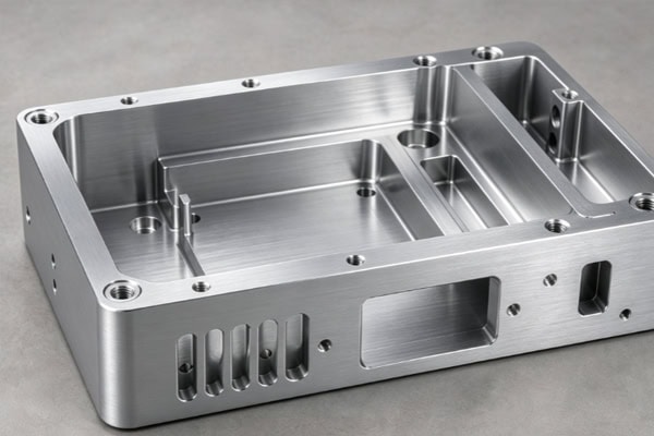
Equipment Housings and Panels
Housings and panels protect the equipment and support interfaces, so their hole positions and mounting dimensions need to match the internal components properly.
- Equipment Chassis: Mounting areas and fixing structures can be arranged according to the layout of circuit boards, modules, and interfaces.
- Panel Structures: Opening dimensions, hole spacing, and connection positions need to be controlled for easy installation of interfaces and control components.
- Electronic Equipment Housings: Mounting posts, reinforcing ribs, and heat dissipation areas can be added according to the available internal space.
Once the housing is machined to the required dimensions, internal components can have a more stable installation space.
Module Bases and Mounting Brackets
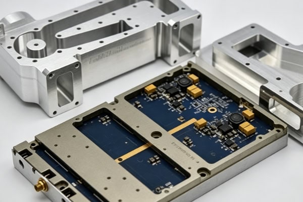
Modules usually need to be fixed in designated positions inside the equipment, making the dimensional relationship between brackets and bases important to overall assembly.
- Module Bases: The relative positions of locating surfaces, mounting holes, and connecting surfaces need to be controlled.
- Mounting Brackets: Fixing holes, reinforcement structures, and clearance areas can be designed according to the internal equipment space.
- Connector Supports: Interface positions need to align accurately with openings in the equipment housing.
Properly designed support structures can reduce interference and positional deviations during module installation.
Heat Dissipation and Precision Structural Components
Some communication equipment operates continuously for extended periods, requiring thermal structures and precision positioning components to meet long-term mechanical requirements.
- Heat Dissipation Structures: Heat transfer can be improved through proper design of thermal surfaces, slots, and mounting areas.
- Precision Connectors: Used for module positioning and fastening, requiring control of critical dimensions and mating relationships.
- Shielding Components: Mounting surfaces, fixing holes, and mating areas can be machined according to the equipment structure.
Functional structural components need to accommodate both mechanical assembly and operating conditions, so machining methods should correspond to their actual applications.
| Communication Equipment Part | Common Material | Recommended Machining Process | Key Quality Focus |
| Equipment Chassis | Aluminum Alloy, Stainless Steel | CNC Milling, Drilling, Tapping | Dimensional accuracy, hole positioning, structural strength |
| Equipment Panel | Aluminum Alloy, Stainless Steel | CNC Milling, Slotting, Drilling | Interface accuracy, appearance quality, flatness |
| Module Base | Aluminum Alloy, Copper Alloy | Precision Milling, Drilling | Positioning accuracy, flatness, assembly fit |
| Mounting Bracket | Aluminum Alloy, Stainless Steel | Milling, Drilling, Tapping | Hole position, rigidity, dimensional consistency |
| Connector Housing | Copper Alloy, Stainless Steel | CNC Turning, Milling, Tapping | Hole diameter, concentricity, connection accuracy |
| Heat Dissipation Component | Aluminum Alloy, Copper | Precision Milling | Flatness, thermal contact surface, dimensional stability |
| Shielding Component | Aluminum Alloy, Stainless Steel | CNC Milling, Drilling | Mounting accuracy, structural fit, surface quality |
The specific material and process should be selected according to the component structure, tolerance requirements, operating environment, and expected production volume.
How Can OEM Machining Accuracy Be Controlled for Communication and Electronic Equipment?
Communication equipment components often contain numerous holes, threads, locating surfaces, and mating areas. Deviations in critical dimensions can affect subsequent assembly, making accuracy control necessary throughout design analysis, machining, and inspection.
Conduct Drawing and DFM Analysis Before Machining
Before production begins, drawings should be reviewed from a manufacturing perspective to identify structures that may affect machining efficiency or part quality.
- Check Critical Dimensions: Verify hole diameters, hole spacing, wall thickness, mounting surfaces, and mating tolerances.
- Analyze Complex Areas: Evaluate tool accessibility and machining stability for deep cavities, thin walls, narrow grooves, and similar structures.
- Plan Machining Datums: Arrange positioning and fixturing methods according to the final assembly requirements.
A thorough manufacturability analysis can reduce the likelihood of process adjustments during production.
Select Machining Processes According to Part Structure
Communication components have different geometric characteristics, so machining methods should be selected according to the specific structure. CNC milling is used for chassis, brackets, panels, and module bases. 5-axis CNC machining is suitable for complex curved surfaces, multi-sided components, and parts requiring fewer setups. CNC turning is used for shaft sleeves, connectors, and other rotary precision components, while drilling and tapping are used for threaded holes, locating holes, and equipment interfaces. Matching the process to the component can reduce positioning errors caused by repeated setups.
Control Product Quality Through Inspection
After prototypes are completed, dimensions need to be verified against the drawings, while critical features should continue to be monitored during batch production.
- Dimensional Inspection: Check parameters such as length, width, hole diameter, and hole spacing.
- Positional Accuracy Inspection: Verify the spatial relationship between mounting holes, locating holes, and interface areas.
- CMM Inspection: Measure critical dimensions and geometric tolerances on complex components.
Inspection results provide clear data for prototype approval and subsequent mass production.
How to Select Materials for Communication and Electronic Equipment OEM?
Mechanical components in communication equipment are affected by factors such as weight, strength, heat dissipation, corrosion resistance, and machinability. Material selection should be based on the function of each component.
Aluminum Alloys for Lightweight Structures
Aluminum alloys offer good machinability and relatively low density, making them suitable for various communication equipment structural components.
- 6061 Aluminum Alloy: Suitable for mounting plates, brackets, and general structural components.
- 6063 Aluminum Alloy: Can be used for certain housings and profile-based components.
- 7075 Aluminum Alloy: Suitable for structures requiring higher strength and stricter weight control.
Proper use of aluminum alloys can provide a suitable balance between equipment weight reduction and structural load-bearing capacity.
Copper, Steel, and Engineering Plastics for Specific Components
Different components have different functional requirements, and some structures require materials selected specifically for thermal conductivity, electrical conductivity, corrosion resistance, or low friction.
- Copper: Suitable for components requiring good thermal or electrical conductivity.
- Stainless Steel: Suitable for structures requiring higher strength and corrosion resistance.
- POM: Can be used for certain low-friction guide and sliding components.
- PEEK: Suitable for specialized structures requiring high temperature and wear resistance.
Selecting materials according to the working environment can reduce mismatches between component performance and actual operating conditions.
How Is a Communication and Electronic Equipment OEM Project Delivered?
From customer requirements to finished product shipment, an OEM project passes through multiple delivery stages. A clearly defined workflow allows procurement teams to track project progress in advance and helps engineering, production, and quality teams maintain consistent information.
Requirement Confirmation and Production Scheduling
At the project launch stage, the order scope and technical documents need to be confirmed before the subsequent production plan is arranged.
- Document Confirmation: Review CAD drawings, 3D models, material specifications, quantities, tolerances, and surface treatment requirements.
- Quotation and Lead Time Confirmation: Determine project costs and delivery schedules based on part quantities, structural complexity, and post-processing requirements.
- Order Scheduling: Confirm production batches, key milestones, and estimated completion dates so customers can coordinate assembly plans.
Complete information at the beginning makes production planning clearer and makes later changes easier to manage.
First Article Production and Customer Approval
Before full-scale production begins, the first article stage can be used to verify actual manufacturing results and establish a consistent reference for subsequent batches.
- First Article Machining: Produce initial samples according to the confirmed drawings and process conditions.
- Dimensional Verification: Inspect critical dimensions, hole positions, geometric tolerances, and other key requirements.
- Issue Adjustment: If deviations are found, adjust programs, machining parameters, or production methods as needed.
Once the first article is approved, subsequent batch production can follow the validated conditions, reducing the risk of large-scale rework.
Batch Production and Process Tracking
During formal production, machine conditions, tool wear, and dimensional changes need to be monitored continuously to prevent deviations after extended machining. Following established processes, checking critical dimensions during production, and recording completed, pending-inspection, and qualified quantities can make actual production progress easier to track.
Final Inspection, Surface Treatment, and Shipment
After machining is completed, subsequent processing and shipment preparation are carried out according to the order requirements.
- Final Inspection: Confirm dimensions, appearance, threads, burrs, and other specified requirements.
- Surface Treatment: Arrange anodizing, sandblasting, passivation, or other finishing processes according to project requirements.
- Packaging and Delivery: Classify and package parts according to their dimensions, quantities, and transportation conditions, then verify shipping information.
Completing the process from final inspection through packaging and shipment allows customers to move directly into subsequent assembly or project validation after receiving the parts.
OEM delivery management for communication and electronic equipment requires technical documents, production milestones, and quality records to remain properly aligned. TiRapid provides customized services covering quotation, DFM analysis, prototype machining, batch production, and inspection, supporting continuous manufacturing for communication and electronic equipment projects.
















