
SMT equipment contains numerous positioning, transmission, guiding, and connecting components that need to maintain stable fit during high-speed operation and frequent movement. For equipment manufacturers, component machining quality can affect assembly efficiency, motion response, and long-term operating conditions. When purchasing CNC-machined components, it is also important to understand the overall process requirements in addition to dimensional tolerances. Planning machining processes according to the specific application of each component can help reduce adjustments during assembly and commissioning.
Which SMT Equipment Components Are Suitable for Precision CNC Machining?
The mechanical structures in SMT equipment are highly customized, and positioning components, moving components, and functional parts can all be manufactured by CNC machining according to technical drawings.
Positioning and Mounting Components
Positioning structures provide connection and positioning between different modules. Machining needs to establish accurate dimensional relationships around reference surfaces and mounting holes.
- Positioning Blocks and Bases: Mainly used for machining positioning holes, mounting grooves, and reference surfaces, with control of hole positions and critical surface dimensions.
- Guide Rail Mounting Bases: Focus on the flatness and parallelism of mounting surfaces as well as the positional accuracy of fixing holes.
- Equipment Mounting Plates: Usually contain multiple hole patterns, steps, and mounting areas, requiring a suitable fixturing strategy based on the structure.
Consistent machining datums can reduce accumulated positional errors during assembly.
High-Speed Motion and Transmission Components
The motion mechanisms of placement equipment frequently accelerate, decelerate, and change direction. Related components need to account for mass distribution, structural rigidity, and changes in inertia.
- Precision Shafts and Connecting Shafts: Require control of outer diameter, roundness, concentricity, and shoulder dimensions. For high-speed rotating structures, dynamic balance should also be evaluated according to rotational speed and geometry.
- Sliders and Motion Brackets: Wall thickness and reinforcing structures need to be properly designed to control weight while maintaining sufficient rigidity.
- High-Speed Motion Structural Components: Cavities and weight-reduction structures can be used to reduce reciprocating mass, while operating conditions should be considered when evaluating vibration risks.
High-speed moving components should not be designed solely for weight reduction. Mass, rigidity, inertia, and vibration characteristics need to be considered together.
Nozzles, Fixtures, and Small Functional Components
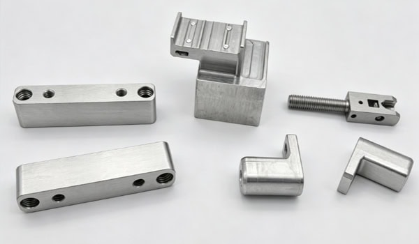
Nozzle connectors, fixture bases, and interface components are usually small in size but contain multiple holes, steps, and mating areas, making them suitable for precision CNC machining. For small structures, tool accessibility, fixturing stability, and machining deformation should be evaluated in advance to ensure that finished components meet assembly requirements.
How Can Long-Term Accuracy Be Controlled During SMT Precision Component Machining?
The operating accuracy of SMT equipment can be affected by machining errors, assembly relationships, motion conditions, and temperature changes. Component inspection therefore needs to be planned according to actual operating conditions.
Conduct DFM and Datum Analysis Before Machining
Before formal production, the component structure should be reviewed based on 2D drawings and 3D models to identify machining priorities and assembly requirements.
- Confirm Critical Dimensions: Focus on hole diameters, hole spacing, thickness, step heights, and mating tolerances.
- Plan Machining Datums: Determine locating surfaces and fixturing datums according to the final assembly relationship.
- Evaluate Complex Areas: Check machining accessibility for deep grooves, thin walls, narrow cavities, and internal corners.
Clarifying manufacturing conditions at an early stage can reduce subsequent process modifications.
Match Machining Methods to the Structure
Planes, hole patterns, and standard cavities can be machined using 3-axis CNC, while multi-sided components and complex curved surfaces can use 4-axis or 5-axis machining according to the actual geometry. Shafts and sleeves are suitable for CNC turning. For components requiring machining from multiple directions, reducing the number of setups appropriately can minimize errors caused by datum changes.
Control Thermal Deformation During Continuous Operation
Equipment operation and changes in workshop temperature can cause dimensional variations. Aluminum alloys have relatively high thermal expansion coefficients, so critical components such as positioning bases and reference plates need to be evaluated for thermal stability according to actual operating temperatures. High-precision structures can reduce the influence of temperature changes through the following measures:
- Material Selection: Evaluate material thermal stability according to the operating environment.
- Structural Design: Arrange wall thicknesses and reinforcing structures appropriately to reduce local thermal deformation.
- Machining Environment: Control temperature variations during machining.
- Inspection Temperature: Ensure that critical dimensional inspection conditions are appropriate for the actual requirements.
- Operating Compensation: For high-precision equipment, temperature compensation can be planned according to actual operating conditions.
Including thermal factors in machining planning can help improve dimensional stability under operating conditions.
Establish a Precision Inspection Process
After machining, key dimensions, geometric tolerances, and complex features can be checked using appropriate inspection methods such as dimensional measurement and CMM, with inspection records retained for quality control and batch production.
| SMT Component Type | Typical Material | Main Machining Focus | Key Inspection Items |
| Positioning Blocks and Bases | Aluminum Alloy, Stainless Steel | Reference surfaces, positioning holes, mounting features | Flatness, hole position, dimensional accuracy |
| Guide Rail Mounting Bases | Aluminum Alloy, Steel | Mounting surface and fixing hole machining | Flatness, parallelism, positional accuracy |
| Motion Brackets and Sliders | Aluminum Alloy, Engineering Plastics | Lightweight structure, rigidity, moving interfaces | Dimensions, rigidity-related features, fit |
| Precision Shafts and Connecting Shafts | Stainless Steel, Alloy Steel, Aluminum Alloy | Turning, concentric features, shoulders | Diameter, roundness, concentricity, dynamic balance where required |
| Equipment Mounting Plates | Aluminum Alloy, Stainless Steel | Multi-hole patterns, steps, reference surfaces | Flatness, hole spacing, position tolerance |
| Fixtures and Small Functional Parts | Aluminum Alloy, Stainless Steel, Engineering Plastics | Small holes, slots, mating surfaces | Critical dimensions, surface finish, assembly fit |
This table provides a quick reference for matching common SMT components with suitable materials, machining requirements, and inspection items.
How Should Materials and Surface Treatments Be Selected for SMT Precision Components?
Material selection needs to consider component weight, loading conditions, motion characteristics, and operating environment. Surface treatment should also account for wear resistance, corrosion protection, dimensional changes, and static control.
Aluminum Alloys for Selected Lightweight Structures
Aluminum alloys have relatively low weight and good machinability, making them suitable for certain mounting plates, brackets, housings, and motion structures.
- Common Structural Materials: Suitable for machining mounting bases, brackets, and equipment housings.
- High-Strength Aluminum Alloys: Can be used for structures requiring higher rigidity and load-bearing capacity.
When aluminum alloys are used for high-speed moving components, structural rigidity and vibration characteristics should also be evaluated rather than using weight reduction alone as the design criterion.
Select Surface Treatments for Wear-Resistant Areas According to Operating Conditions
For aluminum components subject to sliding or friction, hard anodizing and other treatments can be considered according to load, speed, and contact conditions. Hard anodizing can improve surface hardness and wear resistance, but the coating causes dimensional changes, so machining allowance for critical mating areas needs to be planned in advance. For moving areas requiring lower friction, suitable friction-reducing surface solutions can also be selected according to actual operating conditions. The specific process should match the component’s function and mating requirements.
Surface Treatment Needs to Account for ESD Requirements
SMT equipment involves PCBs and electronic components, so some metal structures need to be incorporated into the overall electrostatic control system. Anodized layers are insulating. If a component provides grounding or conductive connections, reliable conductive contact areas need to be reserved. Specific approaches include:
- Local Untreated Areas: Keep metal contact surfaces available for grounding points.
- Reserved Grounding Surfaces: Maintain reliable connections between the component and the equipment grounding structure.
- Compatible Conductive Design: Select the treatment method according to the overall static control requirements of the equipment.
After determining the surface treatment, its influence on assembly dimensions and contact relationships should also be checked.
What Capabilities Should an SMT Precision Component Supplier Have?
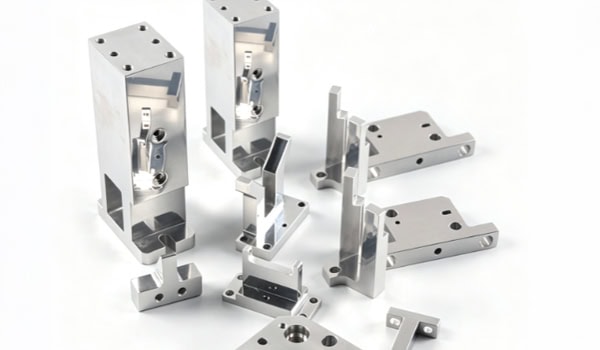
Precision components usually pass through multiple stages from development drawings to final equipment assembly, and the supplier’s engineering support capability can affect project execution efficiency.
From Drawing Review to Prototype Validation
After receiving 2D drawings and 3D models, the supplier needs to review materials, tolerances, structures, and fixturing methods, then verify actual machining results through prototypes.
- Drawing Review: Identify excessively tight tolerances, thin walls, deep cavities, and special mating structures.
- Prototype Machining: Verify critical dimensions, assembly relationships, and surface quality.
- Problem Feedback: Adjust the machining process based on inspection results.
Resolving manufacturing issues during the prototype stage can reduce modification costs after mass production begins.
Support Different Production Volumes
SMT equipment components may progress from individual samples to small-batch testing and then to stable production. Suppliers need to maintain consistent process conditions while continuously monitoring tool wear, equipment conditions, and dimensional changes. A stable production process helps reduce dimensional differences between batches.
Complete Quality Confirmation Before Delivery
After precision components are machined, dimensions, threads, burrs, surface treatment, and quantities need to be inspected. Components should also be classified and protected according to their structures. Specific measures include:
- Quality Confirmation: Verify dimensions, threads, burrs, surface treatment, and quantities.
- Classification: Separate components according to part numbers and assembly relationships.
- Protective Packaging: Use anti-impact and anti-scratch protection for precision mating surfaces.
- Shipment Verification: Confirm that quantities, specifications, and packaging information meet order requirements.
Proper delivery preparation can reduce additional losses during transportation and assembly.
SMT equipment precision component manufacturing requires machining processes to be planned according to component structure, motion conditions, material properties, and operating environment. Procurement teams can focus on the supplier’s drawing review, CNC machining, precision inspection, and batch manufacturing capabilities. TiRapid provides customized machining services to support SMT equipment manufacturers from prototype production to batch manufacturing.
















