The increasing demand for automotive lightweight design has led to greater use of aluminum alloy thin-walled housings, brackets, connectors, mounting bases, heat dissipation structures, and new energy vehicle components. Thin-walled structures can reduce material consumption and component weight while meeting structural requirements within limited installation spaces. However, machining becomes more difficult as wall thickness decreases. Conventional parts generally provide good support during cutting, while thin-walled parts may become affected by cutting forces, clamping pressure, machining heat, and internal material stress after a large amount of material is removed. This can result in deformation, vibration, dimensional changes, and unstable surface quality. Technical materials in the industry also commonly identify deformation control, fixture support, tool paths, machining sequences, and inspection as key considerations for thin-wall machining.
Automotive parts also commonly involve requirements for assembly dimensions, hole positions, sealing surfaces, and connection surfaces, so conventional CNC milling alone may not always be sufficient. Evaluation needs to begin with drawings and 3D models to identify thin-walled areas, deep cavities, unsupported structures, and precision requirements in advance. Clamping, rough machining, semi-finishing, finishing, and inspection processes can then be arranged according to the actual part structure. This approach can reduce problems during machining and help maintain dimensional consistency during batch production.
Why Automotive Thin-Walled Parts Require a Dedicated Machining Solution
Thin-Walled Structures Are Prone to Deformation
Automotive thin-walled parts are commonly found in aluminum alloy housings, mounting brackets, connection structures, and lightweight frames. As a large amount of material is removed, the solid sections that originally provided support gradually become smaller, reducing the ability of the remaining thin walls to withstand cutting forces. If the tool cuts too deeply in a single pass, or maintains excessive contact pressure in a thin-walled area for an extended period, the wall may shift slightly. During machining, the part is held firmly by the fixture and the dimensions may appear normal. After the fixture is released, however, the thin wall may spring back, causing dimensional changes in the finished part.
Vibration Directly Affects Dimensions and Surface Quality
Thin-walled areas have lower rigidity and are more likely to vibrate as the tool passes through them. Vibration does not necessarily result in obvious tool breakage. It may instead appear as abnormal machining marks, increased surface roughness, slight edge burrs, or dimensional variation. For automotive parts with mounting holes, locating surfaces, or sealing surfaces, these errors may further affect assembly. Long thin walls, deep cavity walls, and large-area thin-walled structures require advance evaluation of the tool entry direction and support conditions in the machining area.
Material Removal Sequence Affects Final Accuracy
Thin-walled parts usually require a large amount of material to be removed from a larger workpiece. If the thin-walled area is machined directly to its final dimension and subsequent operations still involve significant material removal, the finished thin wall may be affected by later machining operations. An appropriate machining allowance should be retained, material should be removed gradually, and critical dimensions should be completed when the part is in a more stable condition. For automotive parts with higher precision requirements, the machining sequence should also be determined according to the material, dimensions, and structural characteristics.
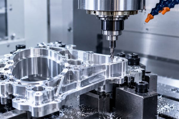
Contents of the CNC Precision Machining Solution for Automotive Thin-Walled Parts
Check Drawings and 3D Models Before Machining
The machining solution starts with product data. Engineers focus on wall thickness, wall height, cavity depth, hole positions, mounting surfaces, overall dimensions, and tolerance requirements. Not all thin walls have the same machining difficulty. Thin walls with the same thickness may have better machining stability when their height is low and both ends are supported. If the wall is high, has a long span, and is connected on only one side, it is more likely to shift during machining. Therefore, DFM evaluation can identify difficult-to-machine areas in advance and provide structural adjustment recommendations based on the actual application. For example, adding local support, adjusting fillets, or reducing excessively deep and narrow areas without affecting assembly or function may improve machining stability.
Select Materials and Machining Methods According to Automotive Part Structures
Automotive thin-walled parts are commonly made from aluminum alloys, but stainless steel, engineering plastics, and other materials may also be used. Different materials behave differently during cutting, so identical machining parameters cannot be applied to all materials.
| Common Materials | Typical Applications | CNC Machining Considerations |
| Aluminum Alloy | Housings, Brackets, Mounting Seats | Control cutting heat and thin-wall deformation |
| Stainless Steel | Connectors, Structural Parts | Control cutting load and work hardening |
| POM | Lightweight Structures, Insulating Components | Pay attention to dimensional changes of material under force |
| PEEK | High-performance Automotive Parts | Control heat and attach importance to dimensional stability |
If the part contains multi-directional curved surfaces, deep cavities, or structures that are difficult to machine from a single direction, multi-axis machining can be used to reduce repeated clamping.
Reduce Thin-Wall Stress Through a Proper Machining Sequence
For typical automotive thin-walled parts, a process such as “stabilize the basic structure—remove material gradually—retain machining allowance—complete thin-wall finishing” can be adopted. During rough machining, the focus is on quickly removing most excess material, but critical thin walls should not be machined to their final condition too early. During semi-finishing, the dimensions are gradually approached while improving the stability of the machining area. Finally, lighter cutting methods are used to finish the thin walls, mounting surfaces, and critical hole positions. This arrangement can reduce the impact caused by excessive cutting in a single operation and help maintain the shape stability of the part throughout different machining stages.
TiRapid CNC Machining Control Solution for Automotive Thin-Walled Parts
Reduce Thin-Wall Deformation Through Proper Clamping
Excessive clamping force may temporarily deform a thin wall, while insufficient clamping force may allow the part to move during machining. Therefore, an appropriate locating method needs to be designed according to the bottom structure, thin-wall position, and machining direction. For complex automotive housings, auxiliary supports can be combined to reduce free movement in thin-walled areas, while clamping positions should be located as close as possible to areas with sufficient rigidity. For batch production, the locating method can be further optimized based on first-piece machining results to maintain relatively stable machining conditions across different production batches.
Control Cutting Pressure Through Tool Paths
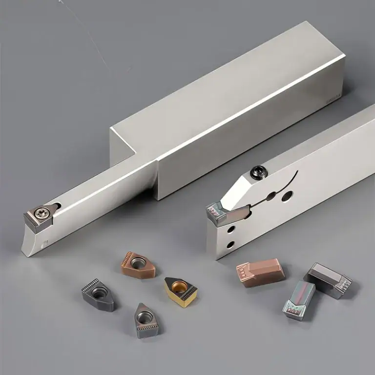
Thin-wall machining is generally unsuitable for prolonged high-load cutting. Tool paths need to be adjusted according to wall height, wall thickness, machining allowance, and tool dimensions. Common practices include reducing the cutting depth per pass, lowering the cutting load in thin-walled areas, and maintaining stable cutting conditions during finishing. For deep cavity structures, tool overhang also needs to be controlled to prevent significant tool deflection.
Confirm Critical Dimensions Through Inspection After Machining
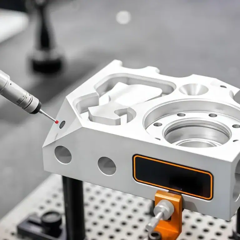
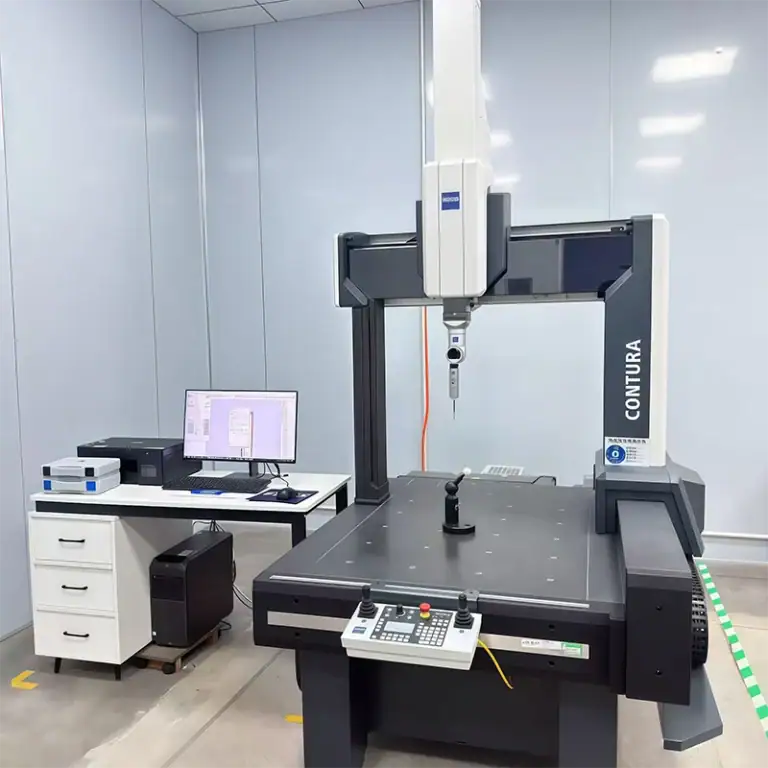
Inspection of thin-walled automotive parts should not be limited to external dimensions. During final delivery, hole diameter, hole-to-hole distance, flatness, positional relationships, wall thickness, and critical assembly areas should also be inspected according to drawing requirements. For parts with higher precision requirements, coordinate measuring equipment can be used for dimensional verification. Public information on the TiRapid website indicates that its services include CMM inspection capabilities for dimensional verification of precision components.
A complete quality control process can include: first-piece dimensional verification; in-process inspection of critical dimensions; finished-part dimensional inspection; and inspection of appearance, burrs, and surface quality.
This helps ensure that the machining results not only meet drawing dimensions but are also suitable for subsequent automotive component assembly.
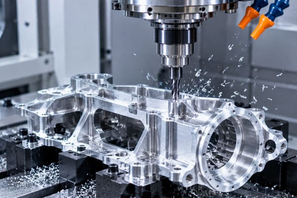
Automotive Thin-Walled Part Machining Services from Prototypes to Batch Production
Focus on Manufacturability During the Single-Part Prototype Stage
Before automotive parts enter formal production, sample validation is usually required. During this stage, CNC can be used to quickly produce actual parts for checking dimensions, assembly, structure, and functional performance. If problems such as deformation in thin-walled areas, inaccessible tool paths, or difficult-to-machine hole positions are identified during prototype machining, the design can be modified before batch production to prevent these issues from entering subsequent manufacturing.
Control Dimensional Consistency During Small-Batch Production
As the quantity of small-batch parts increases, the focus shifts from “producing one qualified part” to “continuously producing stable parts.” Clamping methods, machining programs, tool conditions, and inspection standards need to remain consistent. TiRapid provides services from prototypes to small-batch and large-scale manufacturing, as well as CNC machining, sheet metal fabrication, and 3D printing. According to information published on its website, it supports STP, STEP, and other 3D CAD files and provides DFM recommendations, pricing, and lead-time information.
Consider Delivery Efficiency in Advance for Batch Production
Once automotive thin-walled parts enter batch production, machining time per part, material utilization, tool life, and inspection efficiency all affect the final cost. For structurally complex automotive parts, machining parameters, clamping methods, and inspection procedures can be verified during the prototype stage before applying the validated solution to subsequent batch production. This can reduce repeated trial and error and help maintain a more stable production schedule.
Frequently Asked Questions
Q1: What Is the Minimum Wall Thickness That Can Be Machined for Automotive Thin-Walled Parts?
There is no single wall thickness value that applies to all automotive parts. The actual achievable wall thickness depends on the material, wall height, span, structural support, machining direction, tooling, and precision requirements. Some applications define thin walls as structures below 2 mm or structures with a relatively large height-to-thickness ratio, but this can only serve as an initial reference. A final evaluation still needs to be based on the specific 3D model.
Q2: Why Do Thin-Walled Parts Deform After Machining?
Common causes include internal material stress, cutting forces, clamping pressure, machining heat, and the sequence of material removal. A part may have normal dimensions while mounted in the fixture but change after the fixture is released, which is also an important condition to consider during thin-wall machining.
Q3: Can a Quote Be Provided Directly After Supplying a 3D Drawing?
Yes. TiRapid supports STP, STEP, and other 3D CAD files and can perform DFM evaluation and quotation based on drawings, materials, quantities, and surface finishing requirements.
Q4: Can You Machine Only a Few Automotive Parts?
Single-piece prototypes, small-batch production, and batch manufacturing can be provided according to project requirements. The appropriate method can be arranged according to the part structure, quantity, lead time, and precision requirements.
Automotive thin-walled parts may appear to be simple because their walls are relatively thin, but during actual machining, wall thickness, dimensions, support, clamping, and machining sequence can all affect one another. A problem-free design drawing does not necessarily mean that the part can immediately enter CNC machining and achieve stable results. For aluminum alloy housings, long brackets, deep cavity structures, and large-area thin-walled parts in particular, an improper machining sequence can easily cause deformation during machining or dimensional changes after the fixture is removed.
If you already have 3D drawings, CAD files, or product sketches for your automotive parts, you can send the relevant information to the TiRapid engineering team. We can conduct a DFM evaluation based on the part structure, material, quantity, and precision requirements and provide a CNC precision machining solution based on actual manufacturing needs. Whether you require single-piece prototypes, small-batch production, or subsequent batch manufacturing, an appropriate production method can be arranged according to the project schedule. TiRapid provides CNC precision machining, sheet metal fabrication, and 3D printing services, supporting a complete process from design evaluation and prototype machining to batch manufacturing. If you are temporarily unsure about the machining method or cost, you can also submit your drawings for consultation first, allowing engineers to help confirm machining feasibility, production requirements, and quotation details.
If you are looking for a CNC machining manufacturer for automotive thin-walled parts, welcome to contact TiRapid.
Email: projects@tirapid.com
Phone: +86 760 8999 8536
Send your drawings and basic requirements to begin project evaluation.