Intelligent oil and gas equipment needs to operate under complex conditions involving pressure, temperature, corrosive media, and mechanical loads over extended periods. The manufacturing quality of valve bodies, connectors, sensor housings, and mounting structures can directly affect equipment assembly and operation. For R&D companies and procurement teams, selecting a CNC machining supplier involves more than comparing prices. Material processing capabilities, complex structure machining, dimensional inspection, prototype validation, and batch delivery capabilities also need to be considered. A clearly planned machining solution can help reduce prototype risks and shorten the product development cycle.
Which Parts of Intelligent Oil and Gas Equipment Are Suitable for CNC Machining?
Intelligent oil and gas equipment contains many non-standard precision components. CNC machining can produce customized parts with different structures based on CAD drawings and 3D models, making it suitable for prototypes, small batches, and mass production.
Valve Bodies and Fluid Control Components
Valve bodies and valve covers perform fluid control, connection, and sealing functions. Medium and large oil and gas valve bodies are commonly manufactured from forged or cast blanks before CNC machining is used to produce critical dimensions and functional surfaces. The blank condition and machining allowance should be checked before machining to reduce the risk of internal defects being exposed during finishing.
- Valve Bodies and Valve Covers: Forged or cast blanks can be selected according to the part structure, with key machining areas including flow passages, flange faces, mounting holes, threads, and sealing surfaces.
- Valve Stems and Valve Seats: Focus on controlling outer diameter, concentricity, roundness, and sealing fit dimensions.
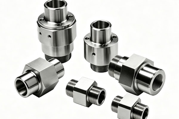
- Flanges and Connectors: Mainly machine end faces, hole spacing, threads, and interface positions to ensure accurate pipeline connections.
For these components, blank quality and CNC machining quality need to be controlled together. Proper inspection of machining allowance and potential defects at an early stage can reduce downstream machining losses.
Sensor Housings and Monitoring Module Structural Components
Intelligent oil and gas equipment commonly includes pressure, temperature, and other monitoring modules. Their structural components need to fit accurately with sensors, electronic circuits, and the main equipment body.
- Instrument Housings: Machined with mounting cavities, interfaces, and fixing structures according to the internal component layout.
- Sensor Connectors: Focus on thread dimensions, interface dimensions, and locating areas.
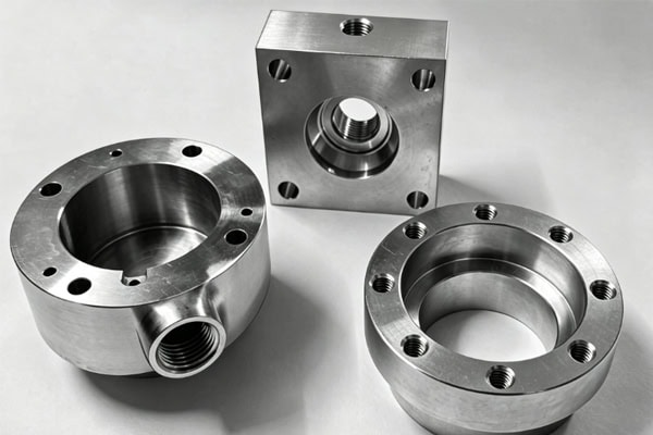
- Mounting Bases: Designed with fixing holes, locating surfaces, and clearance structures according to the available equipment space.
Accurate integration between monitoring modules and the main structure provides a stable mechanical foundation for subsequent installation and commissioning.
Pump, Compressor, and Pipeline Components
Components used in power and fluid transportation systems need to balance dimensional accuracy and structural strength, with different machining methods selected according to their specific geometries.
| Intelligent Oil and Gas Equipment Part | Common Blank / Material Options | Recommended Machining Process | Key Control Items |
| Valve Body, Valve Cover | Stainless Steel, Alloy Steel Forgings or Castings | CNC Milling, Boring, Drilling, Tapping | Machining allowance, flow passages, sealing surfaces, hole positions |
| Valve Stem, Valve Seat | Stainless Steel, Wear-Resistant Alloys | CNC Turning, Precision Machining | Outer diameter, concentricity, roundness, mating dimensions |
| Sensor Housing | Aluminum Alloy, Stainless Steel | CNC Milling, Turning | Cavity dimensions, interface position, threads |
| Instrument Mounting Base | Aluminum Alloy, Stainless Steel | CNC Milling, Drilling | Locating surfaces, hole spacing, flatness |
| Pipeline Connectors | Stainless Steel, Alloy Steel Forgings or Bar Stock | CNC Turning, Milling | Threads, end faces, concentricity |
| Pump and Compressor Structural Components | Stainless Steel, Alloy Steel, Aluminum Alloy | 3-Axis / 5-Axis CNC | Mating dimensions, structural strength |
The specific blank form should be determined according to part size, structural complexity, production volume, and performance requirements rather than assigning a fixed machining route based only on the part name.
How Can CNC Machining Accuracy Be Controlled for Intelligent Oil and Gas Equipment?
Oil and gas equipment components commonly feature deep holes, complex flow passages, thin walls, and multiple mating surfaces. Accuracy control needs to cover drawing analysis, machining positioning, process execution, and quality inspection.
Conduct DFM Analysis Before Machining
Manufacturability analysis of drawings and 3D models before production can identify potential issues between the structural design and actual machining requirements.
- Check Critical Dimensions: Confirm hole diameters, hole spacing, wall thickness, threads, and mating tolerances.
- Analyze Complex Structures: Evaluate tool accessibility for deep holes, narrow grooves, curved surfaces, and internal cavities.
- Plan Fixturing Datums: Determine suitable positioning and fixturing methods according to the final assembly requirements.
Thorough analysis at the beginning can reduce process adjustments and design changes after machining starts.
Match CNC Processes to Part Structures
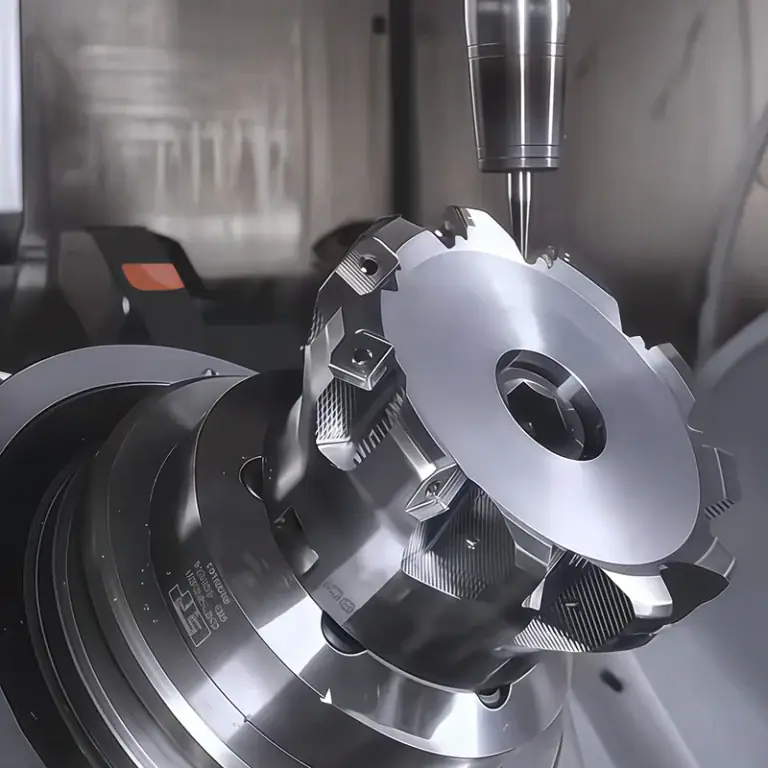
Regular structures can be machined using 3-axis CNC, while complex curved surfaces, multi-sided components, or parts requiring fewer setups can use 5-axis CNC. Rotary components are suitable for CNC turning. Hole patterns, threads, and precision interfaces may also require drilling, tapping, and finishing operations. Proper process selection helps reduce dimensional deviations caused by repeated repositioning.
Establish a Critical Dimension Inspection System
Components used in intelligent oil and gas equipment need to meet assembly and sealing requirements, so the inspection plan should be based on critical features specified in the drawings.
- Dimensional Inspection: Check basic dimensions such as length, diameter, hole diameter, and hole spacing.
- Geometric Inspection: Verify important geometric characteristics such as flatness, concentricity, and perpendicularity.
- CMM Inspection: Use coordinate measuring machines for complex components to verify critical dimensions and geometric tolerances.
Keeping machining data aligned with inspection results makes it easier to control consistency between prototypes and batch-produced components.
How to Select Materials for CNC Machining Intelligent Oil and Gas Equipment?
Materials need to be selected according to the working medium, temperature, pressure, and corrosive environment. For difficult-to-machine materials, tooling, cooling, and cutting parameters should also be considered during the early stages of process planning.
Stainless Steel, Alloy Steel, and Nickel-Based Alloys for High-Performance Structures
Core components in oil and gas equipment may operate under high pressure, corrosive media, or high temperatures for extended periods, placing high demands on material strength and stability.
- Stainless Steel: Can be used for certain valve bodies, connectors, and instrument housings. The specific grade should be selected according to the medium and operating conditions.
- Alloy Steel: Suitable for mechanical structures requiring high strength and load-bearing capacity.
- Nickel-Based Alloys: Materials such as Inconel 625 and Inconel 718 can be used in specialized high-temperature or corrosive environments. However, they exhibit significant work hardening and low thermal conductivity, making them typical difficult-to-machine materials.
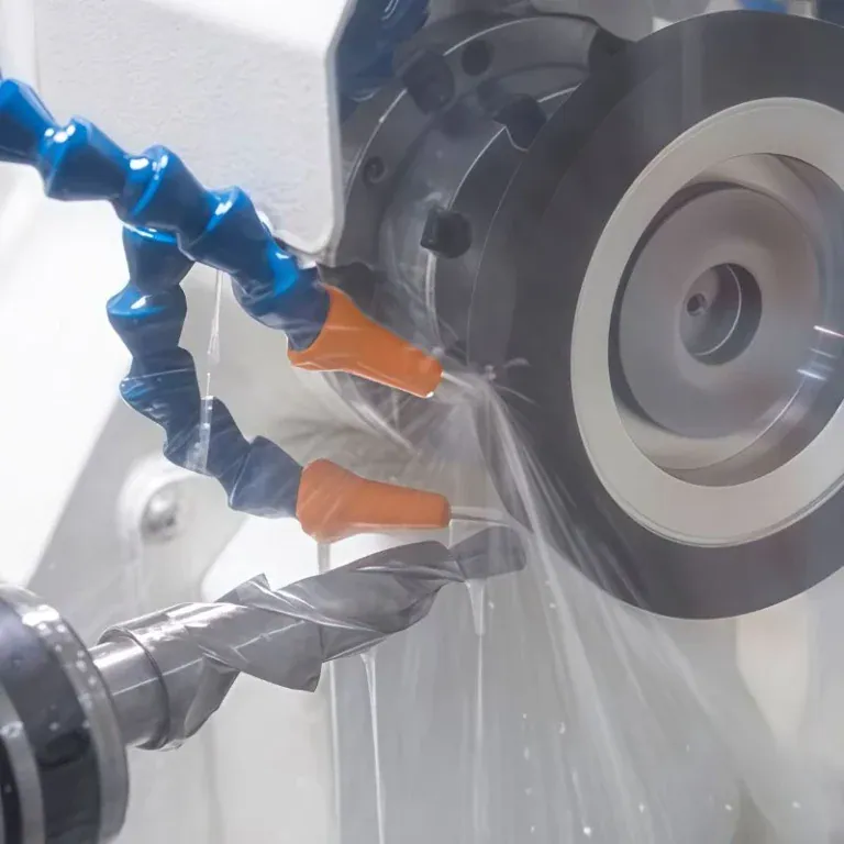
Nickel-based alloys cannot simply be machined using standard steel parameters. Appropriate tooling should be selected according to the material condition and machining operation, combined with rigid fixturing, suitable cutting parameters, and effective cooling to control tool wear and machining heat. The specific process should be confirmed through actual machining trials.
Aluminum Alloys for Lightweight Intelligent Equipment Structures
Some housings, brackets, and bases used in intelligent monitoring equipment need to reduce weight while maintaining good machinability.
- Equipment Housings: Suitable for machining internal cavities, interfaces, and mounting structures.
- Mounting Brackets: Can be milled with weight-reduction pockets, fixing holes, and locating surfaces.
- Module Bases: Used to connect and secure internal modules while balancing weight and structural rigidity.
Aluminum alloys are more suitable for certain non-pressure-bearing structures, while the specific application range should be determined according to the actual operating conditions of the equipment.
How Is a CNC Project for Intelligent Oil and Gas Equipment Completed from Prototyping to Delivery?
Intelligent oil and gas equipment projects usually progress through prototype development, small-batch validation, and batch manufacturing. The efficiency of coordination between these stages can affect the overall product development schedule.
Confirm Drawings, Blanks, and the Machining Plan
At the project launch stage, drawings, 3D models, materials, tolerances, and surface treatment requirements need to be confirmed, while the appropriate blank type is determined according to the part structure. For castings and forgings, material condition, critical dimensions, and machining allowance should also be checked before developing the corresponding CNC machining plan. Aligning design information with blank specifications in advance can reduce machining risks caused by insufficient allowance or blank defects.
Prototype Machining and Small-Batch Validation
Once the product enters the validation stage, prototypes and small batches can be used to verify actual machining results.
- Prototype Inspection: Focus on critical dimensions, interface positions, threads, and sealing areas.
- Process Stability Validation: Monitor tool wear, dimensional changes, and machining surface quality.
- Design Change Response: Update programs, processes, and production schedules according to revised drawings.
Validated process conditions can provide a reference for subsequent batch production and help maintain dimensional stability between different production batches.
Final Inspection, Surface Treatment, and Packaging
After machining is completed, quality confirmation and post-processing should be carried out according to the order requirements.
- Final Inspection: Check dimensions, threads, appearance, burrs, and critical mating areas.
- Surface Treatment: Arrange passivation, sandblasting, anodizing, or other treatments according to the material and operating environment.
- Packaging and Delivery: Classify, protect, and package components according to their structures, then verify quantities and shipping information.
Complete shipment preparation allows procurement, R&D, and assembly teams to coordinate subsequent work more efficiently.
When sourcing CNC-machined components for intelligent oil and gas equipment, buyers can evaluate suppliers based on overall manufacturing capabilities. For projects involving complex flow passages, special materials, and high-precision mating features, prototype validation and batch production plans should also be confirmed in advance. TiRapid provides customized CNC machining services for the oil and gas industry, covering rapid prototyping, precision machining, quality inspection, and batch manufacturing to support complete component production for intelligent oil and gas equipment projects.