
Printers, copiers, automotive door-lock actuators, small gear reducers—POM gears show up in nearly every power-transmission application that is noise-sensitive and does not need to carry heavy loads. POM has one natural advantage for gears: the material is inherently self-lubricating, so gears mesh quietly without additional grease. That does not mean POM gears are easy to make, though. Getting the tooth profile right and keeping the gear running smoothly and quietly for millions of cycles is considerably more involved than cutting ordinary structural parts.
The biggest difference between gear machining and general part machining is this: with ordinary parts, the focus is on getting the overall dimensions right, hole positions accurate, and mating surfaces flat. Gears add an extra layer of precision on top of all that—tooth profile, cumulative pitch error, and radial runout. A gear with a tooth profile error of a dozen microns may sound fine when first installed in a reducer, but after a few dozen hours of operation the noise creeps up and the wear marks across the meshing surfaces become uneven. POM may be softer than metal, but the demands on tooth profile accuracy are no less stringent.
POM Material Characteristics and Suitability for Gear Machining
POM comes in two types: homopolymer and copolymer. Homopolymer POM (with DuPont’s Delrin being the best-known example) offers slightly higher strength and stiffness, but its thermal stability is inferior to that of the copolymer grade. Poor temperature control during machining can cause it to decompose and release formaldehyde gas. Copolymer POM has a much wider processing window and better thermal stability, making it the preferred choice for most gear machining applications. Unless specifically labeled otherwise, the POM sheet and rod stock commonly available on the market is copolymer by default. Among engineering plastics, POM has one of the lowest moisture absorption rates—around 0.2%, compared with PA6, which can absorb up to 3% at saturation. This figure matters a great deal for gears. Gear backlash is typically designed within a range of 0.05 to 0.15 mm. If the material swells from moisture absorption and eats up this clearance, the result is at best louder operation and at worst outright seizure. With POM gears there is little need to worry about dimensional drift caused by humidity changes, which is precisely why many precision transmission designs choose POM over nylon.
POM is not without its drawbacks, however. It has high crystallinity, and its cooling shrinkage during forming is around 2%—considerably higher than that of nylon. When a gear blank is cut from sheet stock and a large amount of material is removed, the release of internal stress will cause the part to deform. If the gear rim is relatively thin, deformation can reach tens of microns. POM is also notch-sensitive. If sharp tool marks or micro-cracks are left at the tooth root, the risk of root fracture after a period of operation is higher than with metal gears. Proper treatment of the root fillet on POM gears is therefore not an embellishment—it is a hard requirement for preventing early failure.
Tool Selection and Configuration
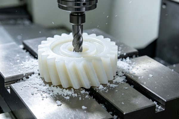
Tool selection for POM gear machining is a step up in rigor compared with general POM part work. The primary constraint is the tooth space. Fine-pitch gears (module 0.5 to 1.5) may have tooth spaces only 1 to 2 mm wide, meaning the tool diameter must be even smaller simply to enter the gap. For a module-0.8 gear, the tooth space at the root measures roughly 1.4 mm, which means the end mill diameter cannot exceed 1.2 mm—and some additional clearance is needed for the toolpath. Small-diameter tools are inherently low in rigidity. POM may be soft, but even a modest depth of cut can cause the tool to deflect elastically, and that deflection shows up directly on the tooth flank as profile distortion—the pressure angle shifts and tooth thickness becomes uneven. Minimizing tool overhang is the most straightforward countermeasure: choose the shortest possible holder and shorten stick-out by every millimeter you can. Small-diameter HSS end mills can cut POM and are adequate for prototypes. In batch production, however, HSS wears quickly—the dimensions of gears cut in the morning may not match those cut in the afternoon. Solid carbide end mills cost more per piece, but their longer life and consistent dimensional performance make them the more economical choice for production runs. Single-flute tools offer the greatest chip clearance and are ideal for finishing tooth flanks; two-flute tools balance efficiency with surface quality and are used more often for roughing and semi-finishing. A helix angle in the 30° to 35° range provides a good balance between chip evacuation and cutting force.
Cutting-edge sharpness is the number-one variable in POM machining. POM does not resist cutting because it is hard; it resists because it is soft. A dull edge pushes material aside rather than severing it, and the result is fuzzy tooth flanks, rolled-over tooth tips, and dimensions creeping off target. The test for whether a tool needs changing is simple: look for a thin, curled-over lip along the tooth tip. If you see one, the edge has dulled to the point of pushing rather than cutting. Chip evacuation is a particular headache in gear work. POM chips are fine powders or short strands—in principle easier to manage than nylon’s long strings. The problem is that the tooth space is both narrow and deep; chips pack inside it and cannot get out. The tool re-cuts the trapped chips over and over, friction heat spikes, and once the local temperature climbs high enough, POM softens and begins to stick to the tool. Compressed-air chip blowing is close to mandatory in this scenario—and the airflow must be directed at the bottom of the tooth space, driving debris out through the slot opening. Coolant alone does not always work well; the liquid struggles to reach the bottom of a narrow slot, and trapped air pockets and dead zones can render local cooling practically ineffective.
Cutting Parameter Selection
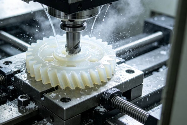
The recommended surface-speed range for POM is 150 to 300 m/min, with the upper end slightly higher than for nylon. In practice, however, few machinists run at the top of that range when cutting gears—the goal is tooth profile accuracy and surface quality, not material removal rate. Take a 3 mm solid-carbide end mill as an example: spindle speed is best kept between 15,000 and 20,000 RPM, corresponding to a surface speed in the 140 to 190 m/min range. Feed per tooth is set at 0.03 to 0.06 mm—a conservative tier compared with general POM machining. Axial depth of cut per pass is limited to no more than 15% of tool diameter. In conventional POM work, 20% or even 40% is common, but gear tooth spaces are narrow and deep and tool overhang is long. The tool deflection caused by an aggressive depth of cut translates directly into tooth profile error, and whatever time is saved will not cover the cost of rework.
The finishing pass on the tooth flank is the most critical cut of all. Depth of cut drops to 0.1 to 0.15 mm, spindle speed stays the same, and feed drops to 0.02 to 0.03 mm per tooth. The toolpath should follow the flank profile rather than cutting across it. Running along the flank keeps the tool-mark direction aligned with the meshing direction, so the gear runs quieter; transverse tool marks act like microscopic washboards on the contact surface—noisier and faster-wearing. For cooling, compressed air with a minimal quantity of lubricant is usually sufficient for POM gear work. The advantage of dry cutting with air cooling is a uniform workpiece temperature field; the finishing pass will not suffer from uneven thermal expansion caused by coolant splashing onto isolated spots. If coolant must be used, a water-soluble type at 5% to 8% concentration is appropriate, with the nozzle aimed at the cutting zone rather than flooding the entire workpiece.
Workholding and Deformation Control
Gear blanks are typically round discs or stepped round parts. Workholding faces two conflicting demands: the part must be held securely, yet it must not be distorted by clamping. POM’s elastic modulus is roughly one-fiftieth that of aluminum. Clamp a blank directly in a three-jaw chuck—the clamping force squeezes the blank into a slight ellipse, and the gear is cut in that distorted state. The tooth tip circle looks round straight off the machine, but once the jaws are released and the part springs back, radial runout exceeds tolerance. The problem is especially severe with thin-walled gear blanks; it is almost unavoidable when the wall thickness drops below 3 mm. Several solutions exist. Where wall thickness permits, leave a clamping boss around the blank periphery, then remove it in a secondary operation after the gear is finished—it adds a step but delivers tangible accuracy gains. If the wall is too thin for a boss, use soft jaws that wrap around the blank to spread the clamping pressure over a larger contact area. For gears with the most demanding accuracy requirements, vacuum fixturing is the ultimate approach—zero clamping-stress deformation—though the dedicated vacuum fixture must be built, and the upfront investment in both tooling and time needs to be factored in.
Centering accuracy during flip-over operations is equally critical. Most gears have features on both faces—a bore with a keyway on one side, a lightening pocket or face step on the other. If the two faces are not aligned to the same axis after flipping, the gear will wobble when mounted on its shaft. A reliable approach is to finish-bore the center hole before flipping, then use that bore as the reference for picking up the part on the second side rather than dialing in on the outer diameter. The OD’s accuracy depends heavily on the preceding operation; the center bore’s accuracy is far more controllable.
Tooth Flank Quality and Root Fillet Treatment
POM gear tooth flanks are typically finished to Ra 0.8 to 1.6 µm. With good equipment and tool condition, a stable finish below Ra 0.8 is achievable. Pushing down to Ra 0.4 demands attention across all three fronts—tooling, parameters, and toolpath strategy: the cutter must be fresh, the feed must be fine, and the toolpath must be smooth, with no sharp directional changes. Tool entry and exit position is a detail that is easy to overlook. Plunging directly into or retracting directly from the tooth flank leaves a visible witness mark; every time the gear rotates past that spot, a periodic clicking sound emerges. The correct approach is to place the entry point at the bottom of the tooth space or at the tip transition zone so that the witness mark stays off the active meshing surface. This adjustment costs next to nothing but delivers an immediate improvement in noise behavior.
Root fillets carry different weight on POM gears than they do on metal gears. POM is notch-sensitive, and an abrupt transition at the root—such as what results from driving a small-diameter tool straight to the bottom to dead-sharpen the corner—dramatically increases the probability of crack initiation under cyclic loading. During machining, allow the tool’s natural corner radius to form the root transition arc; do not chase a sharp corner. Where the drawing calls out a specific root fillet radius, program a radiused transition path in the finishing routine, with the tool radius slightly smaller than the specified fillet to leave the necessary geometric clearance.
Gear Accuracy Inspection Essentials
Measuring only the tooth tip diameter after machining a POM gear is not enough—a correct tip diameter does not mean the gear is within tolerance. Several indicators must be checked:
Cumulative pitch error (Fp) reflects the uniformity of all teeth around a full revolution and is typically controlled within 0.03 to 0.05 mm. If this parameter is off, the gear’s rotational speed will fluctuate periodically and a clear tooth-mesh frequency peak will appear on the noise spectrum. Radial runout (Fr) is primarily influenced by workholding and centering; when these are well controlled, runout usually stays within tolerance, but it must still be measured. Base tangent length is the most direct way to judge whether tooth thickness is correct. The base tangent tolerance for POM gears is generally specified as -0.03 to -0.06 mm, leaving some backlash so the gear runs freely. One measurement detail deserves attention: POM is softer than metal, and the contact force of measuring instruments can indent the surface by several microns. Over-tightening the ratchet on a base-tangent micrometer, or applying excessive force with a tooth-thickness caliper, will produce readings that read on the low side. Consistent measurement technique and controlled hand pressure are the only way to make reliable judgments.
Frequently Asked Questions
How to deal with burrs on the tooth tips after machining POM gears?
Burrs on the tooth tips usually mean the cutting edge has dulled and is pushing material rather than cutting it. Try replacing the tool first and observe the result; do not jump straight to adding a deburring step. If burrs persist with a fresh tool, add a finishing pass around the tooth tip profile at the very end of the cycle, dropping the feed to around 0.01 mm. The effect is more like shaving the burr off than cutting it. Cryogenic deburring offers limited help with POM gears—POM does not become noticeably more brittle at low temperatures, so small burrs will not simply shake loose.
How to choose between POM and nylon gears?
POM clearly outperforms nylon in environments with wide humidity swings—its moisture absorption is an order of magnitude lower, so gear dimensions hardly drift with humidity. POM also offers better fatigue life, with more uniform flank wear after repeated meshing cycles. Nylon’s advantage is superior toughness; it is less likely to suffer tooth fracture under impact loading.
What to do if white smoke or a pungent odor appears during machining?
POM decomposition from overheating releases formaldehyde. A pungent odor or visible white smoke means the cutting temperature has moved beyond the safe range. Stop immediately and check the following in sequence: Is the spindle speed too high? Is the feed rate too low (low feed generates friction heat rather than cutting heat)? Is the compressed-air chip blower working properly? Has the tool dulled? Do not under any circumstances push through and keep cutting. POM thermal decomposition is a self-accelerating process; once it begins, it only intensifies. Continuing will scrap the workpiece, and formaldehyde is also harmful to the operator’s health.
Conclusion
Achieving stable dimensional accuracy, good meshing performance, and long-term operational reliability in POM gears requires integrated consideration of the material’s characteristics, tool selection, cutting speeds, feed parameters, stock allowance control, and downstream quality inspection—all managed together throughout the machining process. For POM gears destined for high-precision applications, choosing a CNC machining provider with proven experience and technical capability can effectively reduce machining errors, improve part-to-part consistency, and provide a reliable foundation for the component’s stable performance in service. If you have requirements for POM gears, precision plastic parts, or other CNC machining work, supplying drawings, samples, or specific application details in advance allows an experienced machining team to develop an appropriate process plan based on the part geometry and operating environment, helping you obtain conforming parts more quickly. Whether for small-batch prototyping or full-scale production, a well-designed machining process enables POM gears to perform at their best.
















