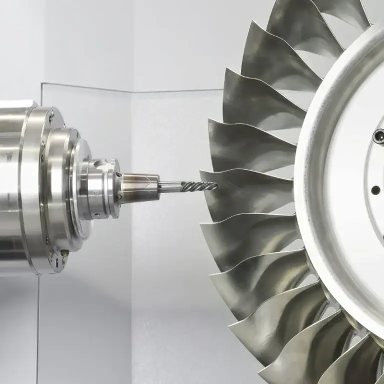
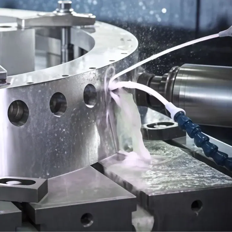
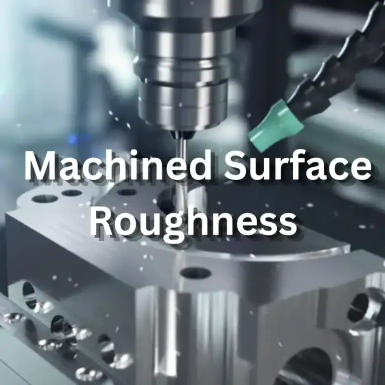
Industrial compressors operate for long hours every day, putting internal components under continuous pressure, mechanical friction, and temperature changes. Even a slight deviation in the crankshaft can cause equipment vibration. Poor clearance between the piston and cylinder may reduce compression efficiency, while an improperly machined sealing surface can increase the risk of gas leakage. For compressor manufacturers, machining is not just about meeting drawing dimensions. Assembly accuracy, operating stability, and service life also matter. CNC machining helps control complex profiles and critical dimensions more accurately, reducing assembly issues and improving equipment reliability.
Which Industrial Compressor Parts Require Precision CNC Machining?
Industrial compressors contain transmission, compression, sealing, and connection components, each with a different function. Shaft components need to maintain rotational accuracy, valve assemblies must provide reliable sealing, and cylinders and connecting structures require precise mounting dimensions. For metal parts with complex geometries and demanding fit requirements, CNC machining offers consistent dimensional control and works well for both custom production and batch manufacturing.

Which Industrial Compressor Parts Are Commonly CNC Machined?
Stable compressor operation depends on accurate fits between critical components. Machining should not focus only on the shape of an individual part. It is also important to consider whether the component may loosen, create friction, or shift out of position after assembly. Common precision-machined parts include:
- Crankshafts and drive shafts: Shaft diameter, roundness, and concentricity must be controlled to reduce runout and vibration during high-speed operation.
- Pistons and piston rods: Their outer diameter and surface quality affect operating clearance. Inconsistent dimensions can increase friction.
- Valve seats and cylinder heads: Sealing surfaces, mounting holes, and connection dimensions need to be accurate to maintain compression efficiency.
Although these components have different structures, each has specific fit requirements. Defining critical dimensions and machining tolerances in advance can reduce assembly adjustments and improve part consistency.
What Materials Are Commonly Used for Industrial Compressor Parts?
Material selection affects load-bearing capacity, wear resistance, and machining difficulty. Carbon steel is suitable for certain load-bearing structures, while stainless steel is often used for components that require corrosion resistance. Alloy steel is a good option for transmission parts that need higher strength and wear resistance. Aluminum alloys are lightweight and commonly used in selected housings and auxiliary structures. The final choice should also account for compressor type, operating pressure, working medium, and temperature—not just material cost.
| Machining Material | Main Characteristics | Common Compressor Parts |
| Carbon steel | Good strength and load-bearing capacity | Connectors and structural supports |
| Stainless steel | Good corrosion resistance | Valve assemblies and media-contact components |
| Alloy steel | High strength and wear resistance | Crankshafts and drive shafts |
| Aluminum alloy | Lightweight and easy to machine | Housings and auxiliary brackets |
Why Are Dimensional Tolerances Important for Precision Compressor Parts?
Industrial compressors contain many moving fits and sealing structures, so even small dimensional deviations can affect equipment performance. The piston and cylinder need proper operating clearance, bearing mounting positions must be accurate, and the contact surfaces between valve seats and valve plates must meet design requirements. Excessive tolerances may cause leakage or vibration, while insufficient clearance can increase friction and interfere with normal movement. CNC machining helps control critical dimensions so components meet assembly requirements more consistently.
How Should CNC Machining Processes Be Selected for Industrial Compressor Parts?
Industrial compressor components vary considerably in shape. Shafts, discs, valve bodies, and cylinder heads cannot all follow the same machining route. An unsuitable process plan may lead to dimensional deviations, surface scratches, or workpiece deformation. Production planning should account for material properties, part geometry, and final fit requirements. Turning, milling, drilling, and finishing operations need to be arranged properly to reduce rework.
Which Compressor Components Are Suitable for CNC Turning and Milling?
Cylindrical parts often require accurate outer diameters and concentricity. CNC turning is suitable for components such as crankshafts, sleeves, and piston rods. Cylinder heads, flanges, and mounting bases usually have flat surfaces, holes, or complex profiles, making CNC milling a better choice. Some components may also require drilling, boring, or precision grinding. The final process selection depends on the engineering drawing and technical requirements.
| CNC Machining Process | Suitable Parts | Key Machining Requirements |
| CNC turning | Crankshafts, sleeves, piston rods | Outer diameter, roundness, and concentricity |
| CNC milling | Cylinder heads, flanges, mounting bases | Flat surfaces, slots, and profiles |
| CNC drilling and boring | Valve bodies, connectors, cylinder components | Hole diameter and position accuracy |
| Precision grinding | Journal surfaces and sealing fits | Surface roughness and dimensional stability |
How Can CNC Machining Reduce Deformation and Burrs in Compressor Parts?
Some compressor components have thin walls, deep holes, or narrow slots. These features can be affected by cutting forces and clamping pressure during machining. Incorrect tool selection or poorly planned machining allowances may result in slight deformation, burrs, and surface defects. Several process controls can help maintain dimensional stability:
- Plan machining allowances: Leave an appropriate allowance after rough machining, then finish the part to avoid excessive stress from a single cutting operation.
- Select suitable cutting tools: Choose tools based on material hardness and part geometry to reduce surface damage during cutting.
- Improve workholding support: Long shafts and thin-walled parts need stable support to minimize vibration and deformation.
- Monitor machining conditions: Check tool wear and chip removal regularly, and adjust cutting parameters when problems appear.
Precision parts should not be inspected only after the final operation. Measurements of shaft diameters, sealing surfaces, and critical hole positions can also be scheduled during production. This helps identify deviations early and prevents defective parts from moving into assembly.
How Can Surface Quality Be Maintained on Compressor Sealing Components?
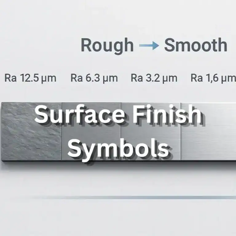
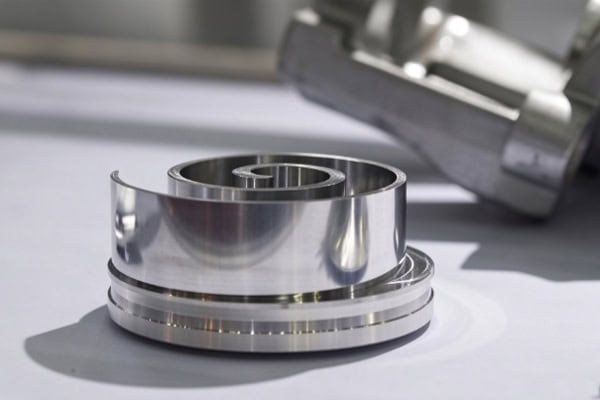
Valve seats, sealing rings, and cylinder mating surfaces directly affect compressor sealing performance. They require controlled surface roughness and flatness. Scratches, pits, or prominent machining marks may cause uneven contact and increase the risk of leakage. Finishing operations should follow the drawing specifications, with precision grinding used when necessary. The dimensions and surface condition of sealing areas should also be inspected. For components that require heat treatment or special coatings, the potential dimensional changes caused by these processes should be considered in advance.
How Can Quality and Cost Be Controlled in Custom Industrial Compressor Machining?
When ordering custom compressor parts, equipment manufacturers usually consider more than machining prices. Lead time, consistent quality, and assembly performance are also important. This is especially true for non-standard components and small-batch orders, where materials, structures, and tolerance requirements can vary significantly. Machining costs cannot be calculated simply by part weight. Clear technical requirements at the beginning help establish an appropriate process plan and reduce extra costs caused by repeated production changes.
What Factors Affect Industrial Compressor CNC Machining Costs?
Part dimensions, material prices, and structural complexity all influence machining costs. Components with deep holes, irregular slots, or multiple precision mating surfaces usually require more machining time. Tight tolerances can also increase finishing and inspection costs. Order quantity, surface treatment, and heat treatment requirements should be included in the quotation. Providing complete drawings and technical specifications helps the machining team plan operations and calculate costs more accurately.
What Should Be Inspected After Industrial Compressor Parts Are Machined?
Visual inspection is only the starting point. Critical dimensions and actual mating conditions are equally important. Different components have different inspection priorities: transmission parts require attention to rotational accuracy, sealing components need surface checks, and connectors must meet mounting requirements. Common inspection items include:
- Dimensional inspection: Measure shaft diameters, hole diameters, lengths, slot widths, and mounting dimensions.
- Geometric tolerance inspection: Check roundness, concentricity, flatness, and perpendicularity to confirm that critical features meet drawing specifications.
- Surface and assembly inspection: Check for burrs, scratches, and machining defects, then verify the fit between mating components.
For parts used in demanding operating environments or applications with strict sealing requirements, inspection criteria should be defined in advance. This helps ensure that parts not only meet dimensional specifications but also perform as required in actual operating conditions.
What Information Is Needed for Custom Industrial Compressor Parts?
When requesting a machining quotation, it is helpful to provide 2D engineering drawings or 3D models. The documentation should specify material grades, critical dimensions, tolerance ranges, surface roughness, and heat treatment requirements. For replacement components, the mating dimensions and operating conditions of the original part should also be included. Complete technical documentation makes it easier to select suitable machining processes for complex non-standard parts and reduces delays and additional costs caused by mid-production changes.
Long-term industrial compressor reliability depends on the dimensional accuracy and machining quality of every critical component. Crankshafts, pistons, valve seats, and connectors may serve different functions, but they all affect transmission, sealing, and overall operating efficiency. A well-planned CNC machining process improves part consistency, reduces assembly issues, and helps lower maintenance costs. TIRAPID provides custom CNC machining services based on industrial compressor drawings and technical requirements. Contact us to discuss your machining needs and request a quotation.