
Thin-walled parts have always been one of the most challenging workpieces in precision manufacturing. Due to their small wall thickness and limited overall rigidity, cutting forces generated during CNC milling, clamping stress, and internal residual stress of the material can all lead to deformation. This is especially critical in aerospace, automotive, medical devices, and high-end equipment, where thin-walled components require high dimensional accuracy, wall thickness consistency, and surface quality. To truly reduce deformation, it is not enough to rely on post-process correction; instead, it must be controlled throughout the entire process, including material selection, fixturing, tooling, cutting parameters, and machining strategy.
Why Thin-Walled Parts Are Prone to Milling Deformation
Understanding the root causes of deformation is essential for developing more effective process control strategies.
Cutting Forces Cause Structural Deflection
Thin-walled parts have inherently low rigidity, and radial cutting forces generated during machining can easily cause local elastic deflection.
- Reasonably reduce single-pass cutting load to minimize tool pressure on thin-wall areas.
- Optimize tool feed direction so that cutting forces are transferred to more rigid support regions.
- Use layered or zoned machining strategies for vibration-prone areas to reduce peak instantaneous loads.
Only by keeping cutting forces within a stable range can the risk of structural deformation be fundamentally reduced.
Clamping Stress Affects Machining Results
If clamping force is uneven or excessive, thin-walled parts may deform during machining and partially recover after unclamping, resulting in dimensional errors.
- Select appropriate clamping positions to ensure more uniform force distribution.
- For low-rigidity parts, use soft jaws, auxiliary supports, or dedicated fixtures to improve stability.
- Control clamping force to avoid local deformation caused by over-tightening.
A stable and properly controlled fixturing method is a key prerequisite for ensuring dimensional accuracy of thin-walled parts.
Material Residual Stress Causes Secondary Deformation
Some aluminum alloys and other metals may contain residual stress after rolling, forging, or heat treatment. As material is gradually removed during machining, stress is redistributed, leading to warping or distortion.
- Select raw materials with more stable stress conditions to reduce stress release during machining.
- For large or high-precision parts, add stress-relief or stabilization processes after rough machining.
- Reasonably distribute machining allowance to ensure a smoother stress release process.
Controlling internal material stress is a fundamental requirement for long-term dimensional stability of thin-walled parts.
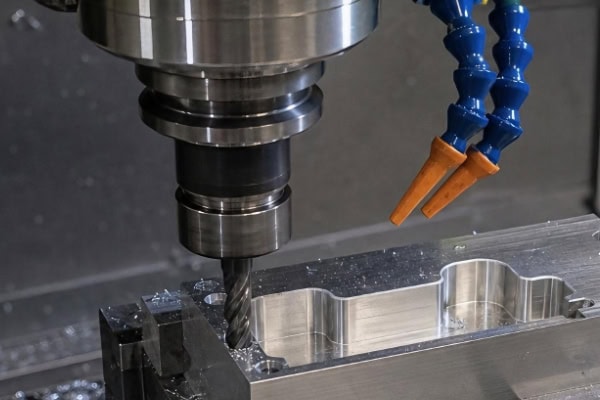
How to Reduce Deformation Through Machining Strategy
Simply reducing cutting speed is not enough; a more rational process plan is required to significantly improve deformation control.
Separate Roughing and Finishing
Machining directly to final dimensions in one step places continuous high cutting loads on thin-walled areas, so a staged approach is necessary.
- In roughing, remove most excess material quickly while avoiding final wall thickness formation.
- Semi-finishing helps balance material distribution and gradually stabilizes the structure.
- Finishing uses small depth of cut and stable parameters to ensure dimensional accuracy and surface quality.
By releasing material in stages, deformation caused by concentrated material removal can be effectively reduced.
Optimize Machining Sequence for Thin-Walled Areas
Machining sequence directly affects stress distribution and force conditions in the part. A well-planned sequence significantly improves stability.
- Prioritize machining of more rigid regions to provide support for subsequent thin-wall operations.
- Avoid continuously machining the same thin-walled area for long periods to reduce heat accumulation and localized stress concentration.
- Use alternating machining strategies for symmetrical structures to balance force distribution.
Proper toolpath planning helps maintain a relatively stable force state throughout the process.
Control Cutting Parameters and Tool Condition
The matching of tools and parameters directly affects machining stability, requiring a balance between efficiency and rigidity.
- Use sharp tools suitable for the material to reduce cutting resistance.
- Reasonably control radial depth of cut to avoid excessive lateral force on thin walls.
- Maintain stable feed rates to ensure smooth cutting and reduce vibration and friction fluctuations.
Through coordinated optimization of tools and parameters, machining deformation risk can be further reduced.
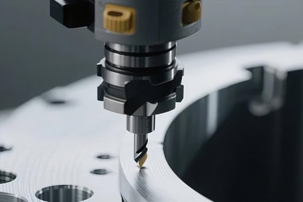
How Fixturing and Auxiliary Support Improve Stability
For low-rigidity thin-walled parts, fixture design is as important as cutting parameter optimization.
Increase Effective Support Area
Traditional point clamping can easily cause localized stress concentration, so support methods should be optimized based on structural characteristics.
- Use support structures that conform to the part profile to increase actual contact area.
- Add auxiliary supports in critical thin-wall regions to reduce free vibration during machining.
- For complex structures, vacuum fixturing or similar methods can be used to improve overall stability.
A more reasonable support design effectively reduces displacement caused by cutting forces.
Reduce Deformation Caused by Fixturing
Fixtures should not only secure the part but also avoid altering its original geometry. Clamping points should be arranged according to wall thickness and structural features, and clamping force should be controlled while ensuring machining safety. After machining, dimensional changes after fixture release should be verified through inspection. Only by considering both clamped and free states can true dimensional control of thin-walled parts be achieved.
Comprehensive Control Is Required to Suppress Deformation at the Source
Deformation in thin-walled parts is usually caused by multiple interacting factors, requiring a systematic process control approach.
Establish a Stable Process Flow
Every stage from raw material to final inspection affects machining results.
- Develop targeted machining strategies based on material properties.
- Determine tooling, fixturing, and machining sequence according to structural characteristics.
- Set inspection checkpoints at key stages to identify deformation trends early.
Systematic process control shifts the approach from “post-correction” to “process prevention.”
Continuously Optimize Processes Through Data
In mass production, relying solely on experience is insufficient to maintain long-term stability.
- Record dimensional variations under different material and parameter combinations.
- Analyze how toolpaths, tooling, and fixturing affect deformation behavior.
- Continuously optimize machining strategies based on inspection data.
Through data accumulation, a stable and reliable machining standard for thin-walled parts can gradually be established.
Conclusion
Dimensional stability of thin-walled structures depends on coordinated control across the entire machining chain rather than optimization of a single process. By controlling material stress in advance, designing appropriate fixturing systems, optimizing toolpaths, and fine-tuning cutting parameters, the conditions that lead to deformation can be progressively reduced during machining. Combined with staged machining strategies, the part can remain in a controlled state throughout material removal, thereby improving final accuracy. TiRapid can provide customized CNC milling process solutions based on specific structural features and precision requirements, helping customers achieve higher consistency and stability in mass production.
















