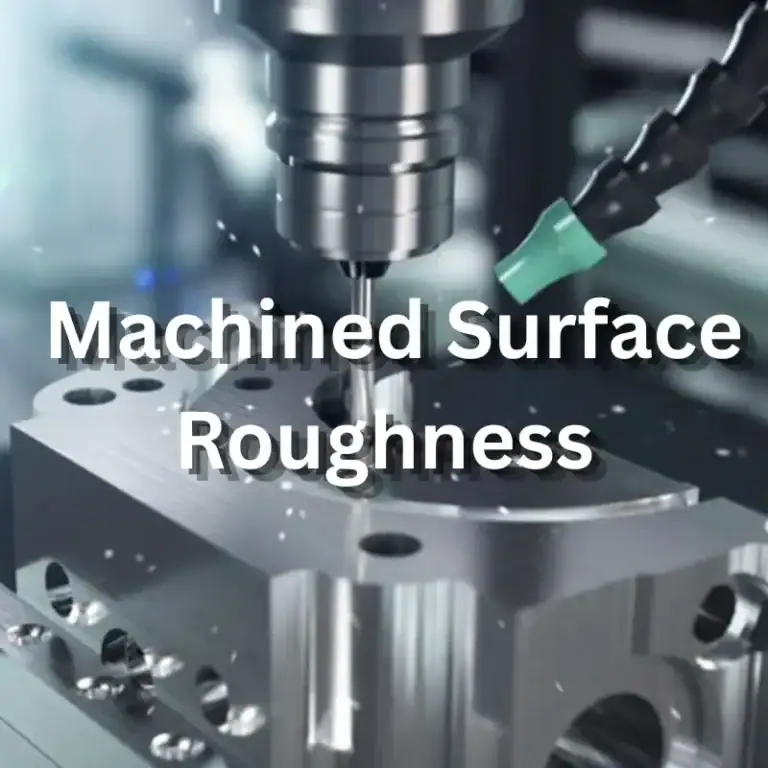
As industrial robots, collaborative robots, and automated equipment continue to advance, robot components require increasingly strict dimensional accuracy, fit tolerances, concentricity, and surface quality. Components such as motor connecting shafts, joint transmission shafts, reducer connectors, precision sleeves, and custom mounting parts often combine rotational features with flat surfaces, holes, threads, and complex contours. Traditional manufacturing may require multiple setups and different machines, increasing positioning errors and production time. Turn-mill machining integrates turning and milling operations on a single machine, allowing multiple features to be completed in one setup or with fewer setups. This provides an efficient manufacturing solution for high-precision robot parts.
Key Advantages of Turn-Mill Machining for High-Precision Robot Parts
Turn-mill machining is suitable for robot components that combine rotational features with complex milled structures. By selecting appropriate cutting tools, machining sequences, and positioning references, manufacturers can improve dimensional consistency, reduce errors caused by repeated repositioning, and increase production efficiency for both customized and batch-produced components.
Fewer Setups Improve Machining Accuracy
High-precision robot components often require external diameters, internal bores, end faces, keyways, and side holes. When these features are machined separately on a lathe and a milling machine, each setup may introduce positioning deviations. Turn-mill machining can complete more operations using a common reference, helping reduce positioning errors between processes.
This method is particularly suitable for motor shafts, robot joint shafts, and reducer interface components. For parts with strict concentricity, end-face perpendicularity, and hole-position requirements, a consistent setup helps improve geometric accuracy. The final process must still be determined according to drawing tolerances, machine capabilities, clamping methods, and inspection results.
Main Turn-Mill Machining Process
The quality of robot components depends not only on machine accuracy but also on process planning, tool selection, material condition, and inspection procedures. A well-planned sequence reduces unnecessary tool movements and repeated machining, making the manufacturing process more consistent.
Drawing review and process planning: Confirm dimensions, tolerances, material specifications, surface roughness requirements, and critical fitting locations. Identify turning, face milling, drilling, and threading features.
- Material preparation and workpiece clamping: Select suitable materials such as aluminum alloys, stainless steel, or alloy steel. Determine the blank dimensions, clamping positions, and machining references.
- Turning and milling: Machine reference features such as external diameters, end faces, or internal bores, then complete side contours, holes, grooves, and threads according to the planned sequence.
- Finishing and deburring: Finish critical dimensions and remove burrs around holes, grooves, and intersecting features to prevent interference during assembly.
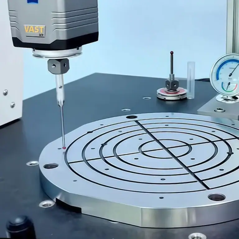
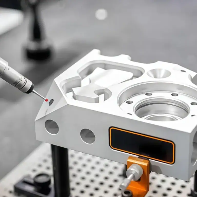
- Dimensional inspection and process adjustment: Use appropriate measuring tools, coordinate measuring machines, or dedicated gauges to inspect critical dimensions. Adjust tool offsets and cutting parameters according to inspection data.
Every stage, from process preparation to final inspection, must match the actual component geometry. For robot transmission parts with tight tolerances, manufacturers should also control thermal deformation, tool wear, and clamping distortion to ensure compliance with drawing requirements.
Improved Efficiency for Complex Parts and Custom Orders
Robot development and equipment upgrades often require non-standard components, such as connecting shafts with eccentric holes, joint parts with multi-directional interfaces, and transmission components combining cylindrical surfaces with complex flat features. Turn-mill machining integrates different cutting operations, reducing the time required to transfer workpieces between machines.
For small-batch custom orders, fewer process changes can reduce repeated setup and handling costs. For recurring production, validated programs, tool paths, and inspection standards help maintain consistency between batches. However, when a component has a simple structure and primarily requires turning, manufacturers should compare production volume, equipment costs, and delivery requirements before choosing turn-mill machining.
Machining Methods and Applications for Robot Components
Robot components have different structural designs and load conditions, so their machining strategies must be selected accordingly. Turn-mill machining is suitable for components that combine rotational features with holes, grooves, flat surfaces, and side features. Typical applications include robot joint transmission systems, servo motor connections, precision positioning components, and automated fixtures.
Machining Robot Transmission Shafts and Rotational Components
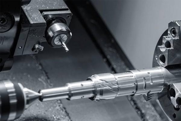
Robot transmission shafts, joint shafts, and connecting shafts commonly require precise control of external diameters, shoulders, concentricity, roundness, and bearing-fit surfaces. Turning is used to machine external diameters, end faces, stepped profiles, and axial bores. Milling can produce keyways, flats, side holes, and positioning features. For shafts with multiple machining requirements, turn-mill machining reduces changes in reference positions and helps control the relationship between features.
For components used in servo drives or robot joints, dimensional accuracy and surface condition at fitting locations affect assembly quality and operational stability. Cutting parameters should be selected according to material hardness, shaft diameter, length-to-diameter ratio, and loading conditions. Proper clamping and support are also important for slender shafts to prevent vibration, bending, and surface defects.
Multi-Hole Joint Connectors and Precision Interface Components
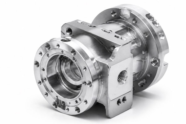
Robot joint connectors, flange interfaces, and sensor mounting brackets may contain center bores, bolt patterns, threaded holes, and lateral positioning surfaces. Turn-mill machining can produce the main rotational features before machining the hole patterns and mounting surfaces, helping maintain a consistent geometric relationship between the holes and the center axis.
These components are commonly used in joint modules, end effectors, precision fixtures, and inspection equipment. Before machining, manufacturers should confirm hole spacing, hole diameters, thread specifications, mounting-surface flatness, and assembly references. For precision hole patterns, finishing operations such as precision boring or reaming may be required. Coordinate measuring machines or dedicated gauges can then verify hole-position accuracy.
Machining References for Different Robot Components
Material selection and machining parameters depend on load capacity, motion speed, working environment, and surface treatment requirements. The following table provides a reference for common robot components. Actual parameters should be determined according to the material, drawing tolerances, and machine capabilities.
| Robot Component | Common Materials | Main Machining Operations | Key Quality Requirements |
| Joint transmission shaft | Alloy steel, stainless steel | External turning, facing, slot milling, drilling | Concentricity, roundness, shaft diameter tolerance |
| Motor connecting shaft | Aluminum alloy, alloy steel | Turning, flat milling, drilling, threading | Fit dimensions, end-face perpendicularity |
| Joint connector | Aluminum alloy, stainless steel | Turning, milling, drilling, finishing | Hole-position accuracy, flatness, assembly stability |
| Precision sleeve | Aluminum alloy, stainless steel | Internal and external turning, boring, facing | Concentricity, bore dimensions, surface roughness |
| End-effector interface | Aluminum alloy, suitable engineering metals | Turning, face milling, hole and groove machining | Positioning accuracy, interface dimensions, repeatable assembly |
Material selection should consider more than cutting performance. Stiffness, weight, wear resistance, and service life must also be evaluated. Aluminum alloys are suitable for lightweight components; stainless steel can be used where corrosion resistance is required; and alloy steel is often selected for transmission components that carry higher loads or require heat treatment.
Functional and Performance Control for High-Precision Robot Parts
Robot components often operate under repeated motion, mechanical loads, and assembly stresses over extended periods. Turn-mill machining must achieve more than dimensional compliance; it must also address geometric accuracy, surface quality, material properties, and batch consistency. By establishing inspection standards for critical dimensions and matching manufacturing processes to component functions, manufacturers can reduce assembly rework and the risk of operational problems.
Critical Dimension Inspection and Quality Control
High-precision machining requires a quality control process that covers first-article verification and batch inspection. For robot components with tight dimensional requirements, finished-part quality should not be judged solely by the machining program or the machine’s stated accuracy. Actual measurements must confirm that critical features comply with the engineering drawings.
- Critical dimension inspection: Use micrometers, bore gauges, calipers, or dedicated gauges to measure shaft diameters, internal bores, step dimensions, and groove widths. Select measuring instruments according to the drawing requirements.
- Geometric accuracy verification: Inspect concentricity, position, perpendicularity, and flatness using suitable measuring equipment and datum references. Coordinate measuring machines may be required for demanding tolerances.
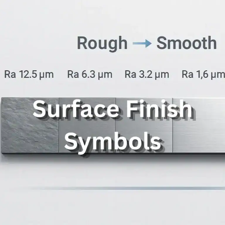
- Surface quality inspection: Check finished surfaces for visible tool marks, burrs, scratches, and other defects. When surface roughness limits are specified, use a surface roughness tester to verify compliance.
- Batch consistency management: Record first-article measurements, tool life, machining parameters, and sampling results. Identify dimensional changes caused by tool wear, machine drift, or material variation.
A complete quality control system helps manufacturers identify deviations earlier and prevent nonconforming components from reaching the assembly stage. For critical transmission parts, inspection records should be retained according to customer requirements to support traceability and process improvement.
Surface Quality, Structural Stability, and Long-Term Performance
The performance of robot components depends on material properties, machining accuracy, surface treatment, and assembly conditions. Transmission shafts and precision sleeves require stable fitting conditions. Joint interfaces need reliable positioning, while end-effector components must meet clamping, locating, or repeated-installation requirements. Excessive deviations in critical dimensions can cause abnormal assembly clearances, increased vibration, or reduced positioning accuracy.
Depending on the application, post-machining operations may include deburring, cleaning, anodizing, passivation, or appropriate heat treatment. Surface treatments can affect final dimensions, particularly for mating bores, shaft diameters, and positioning surfaces. These changes should be included in process planning. Components exposed to cyclic loading should also be evaluated for material strength, fatigue performance, structural transitions, and stress concentration in accordance with the design requirements.
High-precision robot parts turn-mill machining is suitable for manufacturing tasks that combine rotational machining with complex milled features. With appropriate process planning, stable workholding, suitable material selection, and traceable quality inspection, manufacturers can improve dimensional consistency and assembly reliability. This approach supports precision manufacturing for robot joints, transmission components, servo connections, and automated equipment. The final machining plan should be based on component drawings, production volume, performance specifications, and delivery requirements.