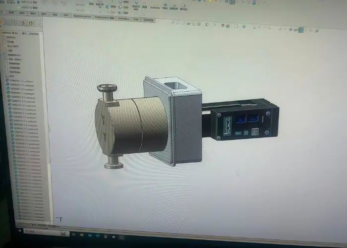
STEP files are one of the most widely used neutral CAD formats in engineering and manufacturing because they make it easier to exchange 3D models between different software systems. They are commonly used to transfer solid geometry, assemblies, and product data without forcing every team, supplier, or manufacturer to work in the same CAD platform.
In this guide, we will explain what a STEP file is, what information it can contain, how it compares with other 3D file formats, and why it is so important for CNC machining, 3D printing, product development, and engineering collaboration.
What Is a STEP File?
A STEP file is a neutral 3D CAD exchange format used to move product model data between different software systems. STEP stands for Standard for the Exchange of Product Model Data and is based on the ISO 10303 standard. Its main purpose is to let engineers, suppliers, and manufacturers share usable 3D design data without relying on the same native CAD program.
What makes STEP files important is their interoperability. Native CAD files are usually best for editing inside the original software, but they are less practical when different teams use different systems. STEP files are designed to preserve usable geometry and product structure in a way that supports cross-platform engineering collaboration.
In real manufacturing workflows, STEP files are widely used for CNC machining, 3D printing, design review, quoting, and supplier handoff. They help reduce software barriers and make it easier to transfer part models between customers, engineering teams, and production partners. That is why STEP remains one of the most widely used neutral CAD formats in engineering and manufacturing.
What Information Does a STEP File Contain?
A STEP file can contain much more than a simple visual 3D shape. In most engineering workflows, it is used to carry solid geometry, surface geometry, part structure, and assembly relationships in a neutral format that can be understood by many CAD systems. Depending on the STEP application protocol and the software used, it may also include additional product information that supports manufacturing, review, and downstream engineering work.
3D Solid and Surface Geometry
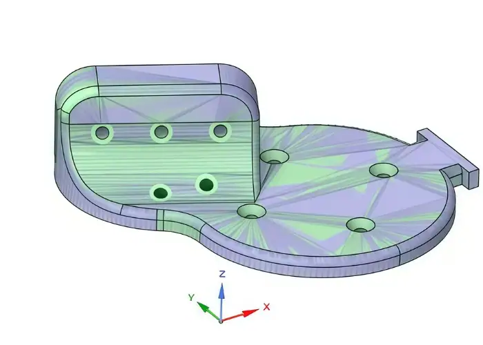
One of the most important things a STEP file contains is 3D geometry. This usually includes solid bodies and surface data that define the actual shape of a part or product. Unlike mesh formats that describe an object as triangles or polygons, STEP files are typically used to exchange CAD-grade geometric models that are more suitable for engineering, machining, and design modification workflows.
This is a major reason STEP files are widely used in CNC machining and product manufacturing. When a supplier receives a STEP file, they are usually working with clean geometric data that is much more useful for quoting, toolpath preparation, and dimensional review than a visual-only or mesh-based format. The file is intended to preserve the shape of the model in a way that remains meaningful across different software systems.
In practice, this means a STEP file is often trusted as a reliable handoff format for machined parts, prototypes, assemblies, and technical design reviews. If the source model is well built, the STEP file can preserve the core part geometry accurately enough for many downstream workflows. That makes it one of the most practical file types for transferring real engineering shapes instead of just approximate visual models.
Part and Assembly Structure
STEP files can also preserve part structure and assembly organization, not just individual shapes. This is important because many products are made of multiple components that must remain grouped and positioned correctly when transferred from one CAD system to another. A useful STEP file does not only show geometry. It can also help maintain how parts relate to each other inside an assembly.
For engineering teams and manufacturing suppliers, this assembly-level information can make collaboration much easier. Instead of receiving disconnected bodies or flattened geometry, the receiving side may be able to understand how the full product is organized. That is especially valuable in supplier handoff, design review, quoting, and production planning, where part relationships matter just as much as individual shapes.
This is one reason STEP files are commonly used for cross-platform product exchange. If the file keeps useful assembly structure, downstream teams can inspect how multiple components fit together without needing the native CAD software used to build the original model. In many practical workflows, this improves communication and reduces the risk of mistakes caused by lost part hierarchy or broken assembly context.
Metadata and Product Information
Depending on the STEP version and workflow, a STEP file may also contain metadata and product information beyond geometry alone. This can include attributes such as part names, layer or color information, product structure details, and in some cases richer model-based definition data such as PMI. The amount of non-geometric information supported depends heavily on the application protocol, software exporter, and importer being used.
This is where STEP protocols such as AP203, AP214, and AP242 become important. Earlier protocols focused more on core geometry and controlled design exchange, while later ones expanded support for richer product data. AP242, in particular, is known for broader support of model-based information and more modern digital engineering workflows.
In practical use, this means engineers should not assume every STEP file carries the same level of information. Some files may transfer only the shape well, while others may also preserve useful metadata for manufacturing, inspection, or collaboration. That is why it is always a good idea to verify what actually survived export and import, especially when the STEP file is being used for supplier communication or downstream production work.
Why Are STEP Files Important in Engineering and Manufacturing?
STEP files are important because they let 3D product data move between different CAD, CAM, and engineering systems more smoothly. In real projects, design teams, suppliers, manufacturers, and customers often use different software. A neutral format like STEP makes collaboration easier by reducing software dependency and improving cross-platform model sharing.
This is especially useful in CNC machining and supplier handoff. A machining supplier can usually open a STEP file, review the geometry, assess manufacturability, prepare a quotation, and begin process planning even without the customer’s native CAD system. That makes STEP one of the most practical formats for RFQs, prototype development, and production sourcing.
STEP files also help reduce communication risk. A 3D model gives manufacturers a clearer view of shape, surfaces, and assembly context than drawings alone. In many workflows, STEP files support design review, simulation, inspection planning, and 3D printing preparation. They are not just file types for storing geometry, but tools for transferring engineering intent into manufacturing.
STEP vs Other 3D File Formats
STEP files are often compared with other 3D file formats because engineers and manufacturers use different formats for different purposes. While STEP is one of the most common neutral CAD formats, it is not the only option. Formats such as STL, IGES, OBJ, and native CAD files all have their own roles. The right choice depends on whether the goal is design exchange, manufacturing handoff, 3D printing, visualization, or long-term engineering collaboration.
STEP vs STL
STEP and STL are both widely used in engineering, but they serve very different purposes. A STEP file is built for CAD data exchange and usually preserves solid or surface geometry in a form that engineering and manufacturing software can work with more effectively. An STL file, by contrast, represents a 3D model as a mesh made of triangles. It is mainly used for 3D printing and does not preserve the same level of product data or geometric intelligence.
This difference is important in manufacturing workflows. If a part is being sent for CNC machining, a STEP file is usually a better choice because machinists and CAM programmers can work from precise CAD geometry rather than a triangulated mesh. STL is often acceptable for additive manufacturing, visual prototypes, or concept models, but it is generally less suitable for precision machining, engineering revision control, or supplier handoff when accurate model interpretation matters.
In simple terms, STEP is better for engineering exchange and manufacturing preparation, while STL is better for mesh-based workflows such as 3D printing.
STEP vs IGES
STEP and IGES are both neutral formats, and both have been used for CAD exchange for many years. However, STEP is generally considered the more modern and more capable option. IGES was widely used in older CAD workflows, especially for transferring surface data, but it is often less reliable for handling full product model structure, assemblies, and richer engineering information.
In practice, STEP has replaced IGES in many modern manufacturing environments because it usually provides better support for solid models and more stable cross-platform exchange. IGES may still appear in legacy projects or in workflows involving older software, but for most current engineering and manufacturing handoff tasks, STEP is the more preferred format.
For a CNC machining supplier, receiving a STEP file is often easier and more useful than receiving an IGES file, especially when the project depends on solid geometry review, assembly understanding, or better translation consistency.
STEP vs OBJ
OBJ is mainly used for 3D graphics, rendering, and visual model exchange. It can store mesh-based geometry and may include texture or visual information, which makes it useful in animation, product visualization, and non-engineering 3D workflows. However, it is not primarily designed for precise CAD-based engineering exchange.
Compared with OBJ, STEP is much more suitable for product development and manufacturing. STEP is intended to transfer engineering geometry and product structure between CAD systems, while OBJ is better suited for visual representation. If a file is being used for quoting, machining, technical review, or downstream engineering work, STEP is usually the better choice.
So while both formats describe 3D objects, they are designed for very different environments. OBJ is mainly visual. STEP is mainly engineering.
STEP vs Native CAD Files
Native CAD files are the original file types created by specific CAD software, such as SolidWorks, CATIA, NX, Creo, or Fusion. These files may contain feature history, sketches, constraints, parameters, and other software-specific data that are useful for editing inside the original system. However, they are not always convenient for cross-platform sharing because the receiving party may not have the same software version or license.
STEP files solve that interoperability problem. They do not usually preserve full native feature history in the same way, but they are much easier to exchange across different CAD environments. This makes them especially useful for supplier communication, manufacturing handoff, and collaboration between teams using different software tools.
Native CAD files are usually better when design edits will continue in the same system. STEP files are usually better when the goal is to share geometry reliably with outside manufacturers, partners, or customers.
What Are AP203, AP214, and AP242?
AP203, AP214, and AP242 are different STEP application protocols. In simple terms, they are different standards within the STEP framework that define how product model data is organized and exchanged. These protocols affect what kind of information can be included in a STEP file and how well different software systems can interpret that information.
What Is AP203?
AP203 is one of the earlier and most widely known STEP protocols. It was mainly developed for configuration-controlled 3D design data exchange, especially in engineering environments where product structure and geometry needed to be transferred between systems. AP203 is often associated with basic solid model exchange and has been widely used in aerospace and other technical industries.
In many cases, AP203 can transfer core geometry successfully, but it may provide less support for some richer model information compared with newer protocols. It is still relevant in some workflows, especially where older CAD systems or legacy data standards remain in use, but it is no longer the most advanced option for broader product data exchange.
What Is AP214?
AP214 was developed to support a wider range of automotive and mechanical design exchange needs. Compared with AP203, it generally offers better support for color, layers, and some additional product-related information. Because of that, AP214 became popular in many mechanical engineering and automotive workflows where more than just basic geometry needed to be shared.
In practical terms, AP214 was often seen as a more capable option than AP203 for richer CAD exchange between different software platforms. Many engineering teams used it when they wanted improved data transfer without relying only on native CAD formats. Even today, AP214 may still be encountered in legacy manufacturing and supplier communication workflows.
What Is AP242?
AP242 is the more modern STEP application protocol and is widely regarded as the direction of current and future STEP-based CAD exchange. It was developed to combine and improve capabilities from earlier protocols such as AP203 and AP214. In addition to solid geometry and assembly data, AP242 is better suited for modern product manufacturing information, model-based definition workflows, and richer digital engineering communication.
For engineering and manufacturing teams, AP242 is especially important because it supports more advanced data exchange needs in a more unified way. Depending on software support, it may better handle PMI, semantic data, assembly structure, and long-term digital product definition workflows. As model-based manufacturing and digital thread strategies continue to grow, AP242 becomes increasingly relevant.
Which STEP Protocol Should You Use?
The best protocol depends on the CAD system, the downstream software, and the level of information that needs to be preserved. In many current workflows, AP242 is the preferred choice when supported because it is more modern and more complete. AP214 may still be common in existing engineering environments, especially in older mechanical design workflows. AP203 may still appear in legacy projects, but it is generally less preferred for new data exchange unless system requirements make it necessary.
For most practical supplier handoff situations, the most important point is not only the protocol name, but whether the receiving side can open the file correctly and get the needed geometry and product information. In real manufacturing communication, successful interpretation matters more than protocol theory alone.
How to Open a STEP File?
A STEP file can be opened in many CAD programs, CAM systems, model viewers, and engineering collaboration tools. Because STEP is a neutral and widely supported CAD exchange format, it is commonly used across product design, machining, simulation, inspection, and supplier communication workflows. In most cases, opening a STEP file is simple: the user imports or opens it through the software’s standard file menu.
Different software systems may handle the file in different ways. Some open STEP files as imported solid bodies that can be reused for downstream engineering work, while others treat them mainly as reference geometry. In manufacturing and supplier workflows, STEP files are often opened for geometry review, manufacturability checks, quoting, and process planning rather than for full feature-based editing.
If a STEP file does not open correctly, the problem is usually related to software compatibility, import settings, file corruption, or translation limits between systems. In those cases, engineers may need to try a different protocol version, re-export the file, or confirm that the receiving software supports the required geometry and product data. So while STEP files are widely compatible, successful opening still depends on both export quality and software capability.
How to Create and Export a STEP File?
A STEP file is usually created by exporting a part or assembly from native CAD software into a neutral exchange format. In most workflows, the designer builds the model in a CAD system and then uses a Save As or Export function to generate the STEP file. The result can then be shared with suppliers, customers, or teams using different software.
Although the export process looks simple, file quality depends on the source model, selected protocol, export settings, and software translation capability. A clean and fully defined CAD model usually exports more reliably than one with broken references, missing geometry, or hidden modeling problems. In practice, good STEP output begins with a well-prepared original model.
In engineering and manufacturing, STEP export is often the handoff step between design and downstream work. It is commonly used for CNC machining quotations, supplier review, 3D printing preparation, and assembly coordination. For that reason, exporting a STEP file should be treated as part of engineering communication, not just a final button click.
How to Convert a STEP File?
A STEP file can be converted into other 3D formats when a project requires a different software environment or downstream workflow. In practice, engineers may convert STEP into a native CAD format for further modeling, into STL for 3D printing, or into a visual format for rendering and presentation. The goal is usually to adapt the same model to a different use.
The conversion process depends on the target format and the software being used. In many cases, the STEP file is opened in a CAD system or translator and then exported into the new format. Some platforms convert the model into editable solid bodies, while others only import it as reference geometry. That difference affects how useful the converted file will be later.
Conversion should be handled carefully because not all data transfers equally well. Geometry may survive, while colors, metadata, assembly structure, or PMI may be reduced or lost. That is why engineers should always check the converted result before using it for manufacturing, quoting, design continuation, or technical review. A converted file is only useful if it still supports the next task correctly.
Common Uses of STEP Files
STEP files are widely used because they provide a practical way to exchange 3D product data across different engineering and manufacturing systems. Their main value is flexibility. A STEP model can move from design to manufacturing, from customer to supplier, or from one engineering team to another without forcing everyone to work in the same native CAD environment.
One of the most common uses of STEP files is CNC machining handoff. When a customer requests a quotation for a custom part, the STEP file often serves as the main 3D model for geometry review, manufacturability assessment, and process planning. It gives the supplier a clearer understanding of the part than drawings or pictures alone and helps support faster technical review.
STEP files are also common in product development, design review, 3D printing preparation, fixture design, and inspection planning. Teams often use STEP when they need to share accurate product geometry across departments or outside partners. Because the format is widely supported, it remains one of the most practical choices for cross-platform engineering collaboration and manufacturing communication.
Best Practices for Using STEP Files
Using STEP files well is not only about selecting the format. It also depends on how the file is prepared, checked, named, and shared. In engineering and manufacturing workflows, a clean STEP handoff can reduce delays, improve supplier communication, and lower the risk of translation problems. A poor handoff can create confusion even if the file opens successfully.
One best practice is to export from a clean and complete CAD model. Hidden geometry issues, broken references, or unnecessary complexity can lead to translation errors later. It is also important to match the export settings to the actual downstream use. Some workflows need only part geometry, while others may require assembly structure, color information, or richer product data.
Verification is equally important. Before sending a STEP file to a supplier or customer, it is wise to reopen it in a viewer or secondary software environment to confirm geometry, scale, and assembly behavior. Clear naming, revision control, and supporting documentation also improve handoff quality. In many B2B projects, the best results come when the STEP file is sent together with drawings, material notes, or manufacturing requirements.
FAQs
Can a STEP file replace a 2D drawing when sending a part to a supplier?
Not completely. A STEP file is excellent for sharing 3D geometry, part shape, and assembly structure across different CAD systems, which is why it is commonly used for supplier handoff and manufacturing review. However, many production requirements such as tolerances, materials, finishes, and inspection notes are still more clearly defined in drawings or supporting documents. In real manufacturing workflows, the strongest handoff usually combines a STEP file with technical documentation rather than relying on the model alone.
Why can the same STEP file look correct in one system but wrong in another?
Because STEP is a neutral exchange format, the file still depends on how each software platform imports and interprets the data. Geometry, assemblies, colors, and product information may not always translate in exactly the same way across different systems. This is one reason engineers often reopen exported STEP files in another viewer or CAD environment before sending them to suppliers or customers. A file that exports successfully is not always a file that will be interpreted perfectly everywhere.
When is it smarter to send a native CAD file instead of a STEP file?
A native CAD file is usually the better option when the receiving team needs to continue feature-based editing in the same software system. Native files may retain sketches, constraints, parameters, and design history that a STEP export typically does not preserve. STEP is generally the better choice for cross-platform sharing, supplier communication, CNC machining review, and broader engineering exchange, while native CAD works better for deeper edits inside the original CAD ecosystem.
If your goal is supplier handoff, which STEP protocol is usually the safest choice?
In many current workflows, AP242 is often the preferred option when both sides support it, because it was developed to combine and extend capabilities from earlier protocols such as AP203 and AP214. That said, the safest choice is still the one your supplier, customer, or downstream software can open correctly and use without translation issues. In practical engineering work, compatibility and successful interpretation matter more than choosing the most advanced protocol on paper.
Conclusion
STEP files remain one of the most practical formats for sharing 3D product data across engineering and manufacturing workflows. They help teams exchange geometry, support supplier communication, improve design handoff, and reduce software barriers between different CAD systems. Whether the goal is CNC machining, 3D printing, product development, or cross-platform collaboration, STEP files continue to play an important role in turning design data into usable manufacturing information.
At TiRapid, we support customers with precision CNC machining and custom manufacturing services for metal and plastic parts. If you need help reviewing STEP files for machining, prototyping, or production, our team can work with your 3D models and technical requirements to support a smoother manufacturing handoff.