
Simultaneous 5-axis machining is an advanced CNC milling process in which three linear axes and two rotary axes move together during cutting. This coordinated motion allows the tool to follow curved surfaces, maintain a controlled cutting angle, and reach multiple sides of a complex component without repeatedly repositioning the workpiece.
This guide explains how simultaneous 5-axis machining works, how it differs from 3-axis and 3+2 machining, why RTCP and machine kinematics matter, how CAM programming controls tool orientation, and what engineers should consider when evaluating accuracy, surface finish, tooling, materials, and part geometry.
What Is Simultaneous 5-Axis Machining?
Simultaneous 5-axis machining uses coordinated linear and rotary movement to control both the position and orientation of the cutting tool. Unlike indexed machining, the rotary axes do not remain fixed while material is removed. They continue moving as the tool travels along the programmed surface.
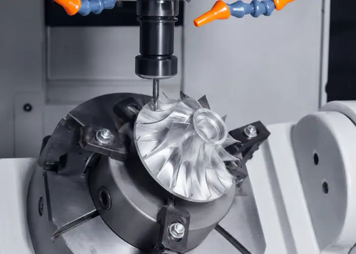
5-Axis Coordinated Cutting Motion
A conventional 3-axis machining center moves along the X, Y, and Z directions. A 5-axis machine adds two rotary movements, commonly identified as A, B, or C axes. These rotary axes may tilt or rotate the workpiece, the spindle head, or a combination of both.
During simultaneous machining, all required axes can change position at the same time. The tool therefore approaches each area at a programmed angle instead of remaining vertical to the machine table. This movement is particularly useful for curved surfaces, deep features, changing wall angles, and geometries with limited tool access.
The objective is not simply to move more machine axes. The process must maintain the correct relationship between the cutter, the workpiece, and the intended surface. Each movement must be coordinated accurately so that tool orientation changes do not create dimensional errors, gouging, or visible surface transitions.
Continuous Tool Orientation
Continuous tool orientation allows the cutter to remain at a suitable angle while following a complex surface. On an impeller blade, for example, the tool may tilt gradually as it moves from the hub toward the outer edge. This keeps the cutter aligned with the changing surface geometry.
Maintaining a suitable tool angle can improve cutting conditions. A ball end mill performs poorly near its center because cutting speed approaches zero at the tool tip. Tilting the cutter allows a more effective part of the cutting edge to contact the workpiece, supporting better chip formation and surface finish.
Continuous orientation also helps avoid nearby walls, fixtures, and part features. Instead of using an excessively long cutter to reach a difficult area vertically, the machine can tilt the tool toward the surface. This can reduce tool overhang, increase rigidity, and improve machining stability.
How Simultaneous 5-Axis Motion Works?
The machine controller must combine programmed tool positions with the mechanical structure of the machining center. It calculates how each linear and rotary axis should move so the cutter follows the intended path while maintaining the required tool vector and contact point.
Linear and Rotary Axis Coordination
The X, Y, and Z axes control the cutter’s location in space. The rotary axes control the angular relationship between the tool and workpiece. During simultaneous machining, a small rotary movement may require corresponding linear movement to prevent the cutter from shifting away from the programmed surface.
This relationship becomes more complex as the tool moves farther from a rotary pivot point. A minor angular change can produce a larger movement at the cutter tip when the tool or spindle assembly is long. Accurate kinematic data is therefore required to calculate the correct compensation.
The CNC controller processes these changes continuously. It receives toolpath data from the CAM program and converts it into machine-specific axis motion. Smooth coordination is essential because unstable rotary movement may create feed-rate variation, witness marks, vibration, or inconsistent cutter engagement.
Tool Position and Tool Vector Control
A simultaneous 5-axis toolpath contains more information than a conventional 3-axis path. The program must define where the cutter should be and which direction the tool axis should point. Together, these values determine the cutter location and orientation at each stage of machining.
Tool orientation can be controlled relative to the surface normal, a guide curve, a drive surface, or another programmed reference. The programmer may add lead, lag, or side-tilt angles to improve cutting conditions, maintain clearance, or keep the tool away from part features.
The selected tool vector affects both quality and machine motion. An aggressive orientation change may force a rotary axis to reverse rapidly or approach its travel limit. A smoother tool vector often produces more stable movement, more consistent feed, and a lower risk of surface marks.
Simultaneous 5-Axis vs 3+2 and 3-Axis Machining
Not every multi-sided component requires continuous rotary motion. Three-axis, 3+2, and simultaneous 5-axis machining each have practical advantages. The correct method depends on whether the cutter angle must change during the cut or only between separate machining operations.
| Comparison Factor | 3-Axis Machining | 3+2 Machining | Simultaneous 5-Axis Machining |
| Active motion | X, Y, and Z | Three cutting axes after rotary positioning | Three linear and two rotary axes together |
| Tool angle during cutting | Normally fixed | Fixed for each indexed operation | Changes continuously |
| Setup requirement | Multiple setups for different faces | Multiple faces in one clamping | Complex surfaces in one clamping |
| Programming difficulty | Relatively low | Moderate | High |
| Best geometry | Prismatic and accessible parts | Angled holes and multi-face features | Curved, twisted, and changing-angle surfaces |
| Collision risk | Lower | Moderate | Higher without proper simulation |
| Surface blending | May show setup transitions | Good between indexed features | Strong on continuous contours |
| Typical cost | Lower | Moderate | Higher |
When 3+2 Machining Is Sufficient?
In 3+2 machining, the rotary axes position the workpiece or spindle at a defined angle and then remain stationary during cutting. The machine effectively performs a 3-axis operation from a different orientation. This method is suitable for angled holes, pockets, faces, and features with fixed directions.
Because the rotary axes are locked during cutting, toolpaths are generally easier to program, simulate, and optimize. Machine movement is also more predictable. For parts with several planar features but no continuously changing surfaces, 3+2 machining can provide excellent accuracy with less programming complexity.
Using simultaneous motion unnecessarily may increase programming time and collision risk without improving the part. Engineers should choose 3+2 machining when indexed orientations provide adequate tool access, surface quality, and tolerance control. The most advanced machining method is not automatically the most efficient one.
When Simultaneous Motion Is Required?
Simultaneous 5-axis machining becomes valuable when the tool angle must change continuously along the cutting path. Typical examples include turbine blades, impellers, propellers, orthopedic components, freeform mold surfaces, port geometry, and parts with changing draft or undercut conditions.
These components cannot always be divided into simple indexed operations. Locking the rotary axes may create unreachable areas, poor cutter contact, excessive tool extension, or visible transitions between toolpaths. Continuous movement lets the cutter follow the geometry without stopping to reposition the workpiece.
The process is also useful when surface blending is critical. By maintaining uninterrupted cutter motion across adjacent areas, simultaneous machining can reduce setup-related mismatch and toolpath boundaries. This can decrease manual polishing and improve the consistency of functional contoured surfaces.
RTCP and Machine Kinematics
Rotary axis movement changes the location of the tool tip relative to the machine coordinate system. RTCP, TCP, or equivalent tool-center-point control functions compensate for this movement. They allow programmers to work with the intended cutting point instead of manually calculating every machine pivot movement.
How RTCP Maintains the Tool Center Point?
RTCP stands for Rotating Tool Center Point. When a rotary axis changes angle, the control adjusts the necessary linear axes so that the programmed tool tip remains at the intended location. Without this compensation, tilting the spindle or table could shift the cutter away from the workpiece surface.
The function uses machine kinematics, tool length, rotary pivot locations, and axis positions to calculate compensation. If the tool length changes, the controller incorporates the new value into its calculations. This makes accurate tool measurement and machine calibration essential for reliable results.
RTCP simplifies toolpath execution, but it does not correct every programming or setup mistake. Incorrect tool length data, inaccurate pivot calibration, fixture errors, or a poorly configured post-processor can still produce dimensional deviation. The control function must be supported by a verified machining system.
Kinematic Calibration and Tool-Length Accuracy
Machine kinematics describe the physical relationship between the linear axes, rotary axes, spindle, table, and pivot points. The controller needs accurate values for these relationships because every rotary movement affects the calculated location of the cutter tip.
Small calibration errors can become visible when the rotary axes move through large angles. A part may machine correctly at one orientation but show mismatch when approached from another direction. Regular rotary-axis calibration helps reduce these orientation-dependent errors and supports consistent multi-axis accuracy.
Tool length must also be measured correctly. A tool that is longer or shorter than the value stored in the control changes the effective cutter position during rotary movement. Precision work may require tool probing, thermal compensation, and verification cuts before machining critical finished surfaces.
CAM Programming and Toolpath Verification
Simultaneous 5-axis machining depends heavily on CAM software, machine simulation, and a properly configured post-processor. The programmer must manage tool orientation, rotary-axis behavior, collision clearance, feed control, surface engagement, and the physical travel limits of the machine.
Toolpath and Post-Processor Control
The CAM system calculates cutter positions based on the part model, selected tool, machining strategy, and tool-axis rules. It may generate swarf cutting, flow-line, multi-axis contouring, blade machining, or surface-normal toolpaths depending on the geometry and finishing requirements.
The post-processor converts this neutral toolpath into machine-specific CNC code. It must understand the machine configuration, rotary-axis directions, pivot distances, control functions, and axis limits. A post built for one 5-axis machine may not generate safe motion for another configuration.
Post-processor validation should include controlled test parts and machine simulation. Correct surface geometry in CAM does not guarantee correct axis movement at the machine. Rotary unwinding, angle selection, feed output, and RTCP commands must all match the actual machine and controller.
Collision Avoidance and Axis Limits
Collision checking must include more than the cutting edge. The CAM simulation should evaluate the tool holder, spindle, rotary table, fixture, clamps, stock, and finished part. Tilting the tool can improve access, but it can also move larger machine components closer to the workpiece.
Rotary axes have travel limits and may choose different angular solutions for the same tool orientation. A toolpath that crosses a limit may force the machine to rewind or rotate unexpectedly. These movements can interrupt cutting, create marks, or increase collision risk if they are not planned.
A stable program avoids unnecessary rotary movement. Tool vectors should be smoothed, fixtures should provide clearance, and the preferred machining orientation should remain within a safe axis range. Complete digital simulation is especially important before cutting expensive materials or high-value components.
Tooling, Workholding, and Material Behavior
The additional access provided by simultaneous 5-axis machining changes how engineers select cutters and fixtures. Better approach angles can shorten tool overhang, but the workpiece must still remain rigid while the table or spindle moves through multiple orientations.
Cutting Tool Selection and Reach
Shorter tools are generally more rigid than long-reach cutters. By tilting the tool or workpiece, a 5-axis machine can often reach deep surfaces without excessive extension. This reduces deflection and vibration while allowing more stable feeds, better dimensional control, and improved surface consistency.
Ball end mills are common for freeform finishing, but barrel cutters, tapered cutters, lollipop tools, and multi-axis side-cutting tools may also be used. The best cutter depends on surface curvature, corner geometry, access angle, material, and required finish.
Tool-holder clearance must be considered with the cutting edge. A holder that is too large may collide when the tool tilts toward a wall. Slim holders improve access but may reduce rigidity. Tool selection should balance reach, holder clearance, cutting pressure, and expected tool life.
Workholding and Material Stability
Five-axis fixtures should expose as much of the workpiece as possible while maintaining adequate support. The fixture must remain clear of the cutter and spindle through the full rotary motion. Low-profile clamps, dovetail fixtures, custom soft jaws, and sacrificial bases are commonly considered.
The machining sequence should preserve rigidity. Removing too much material early can leave thin blades, walls, or freeform sections that vibrate during finishing. Roughing, semi-finishing, and finishing operations should be arranged so the remaining stock supports the component until critical surfaces are complete.
Material behavior also influences strategy. Aluminum supports high cutting speeds but may distort when residual stress is released. Stainless steel can work-harden and generate heat, while titanium concentrates heat near the cutting edge. Each material requires appropriate engagement, coolant, tool coating, and finishing allowance.
Tolerances, Surface Finish, and Quality Control
Simultaneous 5-axis machining can reduce setup-related variation, but the final tolerance still depends on the complete manufacturing system. Machine calibration, tool condition, fixture rigidity, material stability, thermal behavior, programming, and inspection all influence the finished component.
Accuracy Across Multiple Surfaces
Machining several surfaces in one clamping reduces errors caused by removing and repositioning the part. Datum relationships remain connected to the original setup, which can improve the position of holes, contours, faces, and curved features relative to one another.
However, rotary-axis accuracy becomes more important. Linear positioning may be precise while rotary pivot error creates variation at different angles. The farther the cutting point is from the rotary center, the more a small angular or pivot deviation can influence the actual surface location.
Tolerances should be assigned according to function. Not every freeform surface needs the same dimensional control as a bearing seat, sealing feature, alignment hole, or assembly datum. Clear drawings help the manufacturer focus calibration, finishing, and inspection on the most critical relationships.
Surface Finish on Complex Contours
Surface finish depends on cutter contact, stepover, feed rate, tool orientation, machine motion, and material response. Simultaneous 5-axis machining can keep the cutter away from inefficient contact areas and maintain a more consistent effective cutting radius across a contoured surface.
Poorly controlled rotary motion can still leave marks. Rapid angle changes, axis reversal, feed reduction, or tool-vector instability may create visible bands and surface mismatch. Smooth orientation control and consistent cutter engagement are essential when machining polished molds, blades, or visible product surfaces.
Inspection may include CMM measurement, optical scanning, surface roughness testing, profile analysis, or comparison with the CAD model. Complex components often require inspection from multiple directions, so datum planning should connect the machining setup with the final measurement strategy.
Benefits and Limitations of Simultaneous Machining
The main value of simultaneous 5-axis machining comes from combining access, continuous tool orientation, and setup reduction. It can improve complex-part production, but it also adds programming, machine, tooling, and quality-control requirements that may not be justified for simpler components.
| Engineering Factor | Potential Benefit | Possible Limitation |
| Complex geometry | Reaches curved and changing-angle surfaces | Requires advanced CAM programming |
| Number of setups | Machines more features in one clamping | Demands open and stable workholding |
| Tool length | Allows shorter, more rigid cutters | Holder and spindle clearance remain critical |
| Surface finish | Maintains better cutter contact | Rotary motion can create marks if unstable |
| Accuracy | Reduces repositioning error | Depends on kinematic calibration |
| Cycle time | Combines operations and reduces handling | Simulation and programming take longer |
| Production cost | Can lower total cost on complex parts | Machine rate and engineering cost are higher |
| Process risk | Can complete high-value parts efficiently | Collision consequences may be severe |
Where Simultaneous Machining Adds Value?
The process adds the most value when the component has continuous curved surfaces, difficult access, multiple orientations, or critical relationships between features. In these cases, fewer setups and shorter cutters can reduce machining risk and improve dimensional consistency.
It may also reduce downstream work. A smoother continuous toolpath can decrease blending, hand polishing, and setup correction. For mold surfaces, aerodynamic components, and medical geometries, reducing manual finishing helps preserve the intended CAD form and dimensional accuracy.
High-mix and low-volume production can also benefit when one flexible fixture and verified program replace several dedicated setups. The machine may have a higher hourly rate, but total manufacturing cost can be lower when setup labor, inspection, rework, and secondary finishing are considered.
When Another Process Is More Practical?
Simple prismatic parts do not automatically benefit from simultaneous machining. If the component consists mainly of flat faces, straight pockets, and accessible holes, a 3-axis or 3+2 process may produce the part faster with simpler programming and lower machine cost.
Simultaneous 5-axis machining is also not always the best roughing method. Heavy stock removal may be more efficient on a rigid 3-axis or horizontal machining center using larger cutters and deeper cuts. The part can then move to a 5-axis process for semi-finishing and complex final features.
The decision should be based on total process risk rather than machine capability alone. Engineers should compare programming time, cycle time, setup count, fixture cost, inspection effort, surface requirements, and expected quantity before selecting the machining route.
Design Considerations for Five-Axis CNC Parts
A part does not need to look highly complex to benefit from 5-axis machining, but its geometry must justify continuous tool movement. Early design review helps determine whether the required surfaces are machinable, inspectable, and accessible without creating unnecessary cost.
Tool Access and Feature Geometry
Deep cavities, narrow channels, undercuts, and closely spaced walls should be reviewed for cutter and holder clearance. A surface may be reachable by the tool tip but blocked by the holder or spindle body when the machine tilts to the required angle.
Internal corner radii should match practical cutter sizes. Simultaneous motion improves access, but it does not create perfectly sharp internal corners with a rotating cutter. Small radii require smaller tools, which may increase machining time, deflection risk, and tool wear.
Designers should also consider the required tool angle. If a feature can only be reached near a machine’s rotary limit, production may become less stable. A small geometry change, larger clearance radius, or modified wall angle can improve tool access without changing the component’s function.
Datums, Tolerances, and Inspection
Functional datums should be located on stable and measurable surfaces. The machining supplier needs a clear relationship between the freeform geometry and critical holes, interfaces, mounting faces, or sealing features. Poor datum definition makes both programming and inspection more difficult.
Tight tolerances should be concentrated on features that affect assembly or performance. Applying the same tolerance to every contoured surface can add programming, finishing, and inspection cost without improving the final product. Surface profile callouts are often more useful than excessive point dimensions.
Inspection access should be reviewed during design. A feature that is difficult to reach with a cutting tool may also be difficult to measure with a conventional probe. Optical scanning, custom fixtures, or specialized gauges may be required for deep or highly curved geometry.
Applications of Simultaneous 5-Axis Machining
Simultaneous machining is used where surface complexity, tool access, and feature relationships make conventional setups inefficient. It is most valuable when the part must maintain precise geometry across several changing orientations or continuous three-dimensional surfaces.
Aerospace and Energy Components
Aerospace parts such as impellers, blisks, turbine blades, airfoils, and structural components often contain twisted surfaces and thin sections. Simultaneous motion allows the cutter to follow blade geometry while maintaining clearance from adjacent surfaces and supporting controlled tool engagement.
These parts are frequently machined from aluminum, titanium, stainless steel, or high-temperature alloys. Material value and machining difficulty make collision prevention, tool-life management, and process verification especially important. Stable semi-finishing and finishing strategies help protect the component after major stock removal.
Energy and fluid-handling components may also include impellers, pump rotors, ports, and flow passages. Surface continuity affects fluid behavior and efficiency, so controlled toolpaths and consistent finishes can be functionally important rather than only cosmetic.
Medical, Mold, and Precision Tooling Parts
Medical components may include orthopedic implants, surgical instruments, prosthetic structures, and custom anatomical parts. Their organic forms, controlled surfaces, and changing tool angles make simultaneous 5-axis machining useful for producing complex geometry from biocompatible metals and engineering plastics.
Mold and die components often contain deep cavities, varying draft, sculpted surfaces, and difficult corner access. Five-axis machining can shorten cutters, improve surface contact, and reduce the number of mold insert setups. This may also decrease polishing on complex cavity and core surfaces.
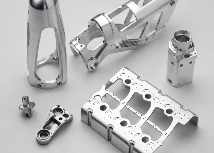
Precision tooling, robotic components, and automation parts can benefit when several angled features must remain accurately related. For specialized applications, component design and manufacturing requirements can vary significantly depending on the equipment and operating environment. One-setup machining helps control hole position, mounting interfaces, sensor features, and contoured working surfaces without accumulating error through repeated re-clamping.
FAQs
Is simultaneous 5-axis machining always more accurate than 3+2 machining?
Not always. Simultaneous machining can reduce setup error and improve continuous surface blending, but its accuracy depends on rotary-axis calibration, RTCP settings, tool measurement, programming, and machine condition. For fixed-angle planar features, a stable 3+2 operation may be simpler and equally accurate.
What parts truly require simultaneous 5-axis motion?
Parts with continuously changing surface angles, twisted blades, impellers, freeform contours, difficult undercuts, or complex tool-clearance requirements are strong candidates. Parts with only angled holes, flat faces, or fixed-direction pockets can often be produced effectively with 3+2 machining.
How does RTCP affect five-axis machining accuracy?
RTCP compensates for the movement of the tool tip when rotary axes change position. It uses machine kinematics and tool-length data to coordinate the linear axes. Incorrect calibration or tool data can still create errors, so RTCP must be supported by verified machine and setup information.
What is the main failure risk in simultaneous machining?
One of the main risks is an undetected collision involving the tool, holder, spindle, fixture, table, or workpiece. Other risks include rotary-axis reversal, tool-vector instability, excessive feed variation, poor calibration, and surface gouging. Complete simulation and controlled program verification are essential.
Conclusion
Simultaneous 5-axis machining provides continuous control of tool position and orientation, making it suitable for complex surfaces, difficult access, and parts that require accurate relationships across multiple directions. Its value depends on geometry, machine kinematics, RTCP, programming quality, tooling, workholding, material behavior, and inspection planning.
At TiRapid, we provide precision CNC machining services for custom metal and plastic parts, helping customers produce complex five-axis components with controlled toolpaths, dimensional accuracy, surface quality, and reliable performance for demanding engineering applications.
















