
Reaming is a precision hole-finishing process that uses a reamer to refine the size, roundness, straightness, and surface finish of a pre-drilled or bored hole. It removes only a small amount of material from the hole wall, making it suitable for dowel pin holes, bushings, shafts, bearing seats, sealing holes, and close-fit assembly features that require tighter control than drilling alone can provide.
This guide explains how reaming works, how it differs from drilling and boring, what reamer types are commonly used, how to choose the right tool, and which process parameters affect hole accuracy.
What Is Reaming?
Reaming is a finishing operation used to slightly enlarge and improve an existing hole after drilling, boring, or casting. Instead of creating a hole from solid material, a reamer follows the existing hole path and removes a thin, controlled layer to improve diameter accuracy, roundness, and surface condition.
In precision machining, reaming is commonly used when a drilled hole is not accurate enough for final assembly. Standard drilling may leave tool marks, size variation, poor roundness, or slight positional error, while reaming can bring the hole closer to a controlled fit.
A well-controlled reaming process can commonly achieve tolerances around ±0.005 mm in precision work and surface finishes around Ra 0.2–0.8 µm, depending on material, tool quality, machine rigidity, coolant, and hole preparation. These values make reaming useful for parts that require smooth sliding, press fits, accurate alignment, or sealing performance.
What Is The Function Of Reaming?
The function of reaming is to improve a pre-machined hole so it meets final size, fit, roundness, and surface finish requirements. It is not mainly used for heavy material removal, but for controlled final finishing.
Improves Dimensional Accuracy
Reaming improves dimensional accuracy by removing a small, predictable amount of stock from the hole wall. In high-precision setups, reamed holes can often reach tolerances around ±0.005 mm or tighter when the machine, fixture, reamer, and pre-hole condition are properly controlled.
This makes reaming suitable for H7 fits, dowel pin holes, locating holes, bearing bores, and close-fit mechanical assemblies. Compared with drilling, reaming provides a more controlled final diameter because the reamer has multiple cutting edges and a guided cutting geometry.
The pre-hole must still be accurate enough for the reamer to follow. If the drilled or bored hole is severely misaligned, tapered, or out of round, reaming may improve surface and size but cannot fully correct the hole position.
Enhances Roundness And Concentricity
Reaming enhances roundness and concentricity by using a guided, multi-flute cutting action. The reamer stabilizes inside the existing hole and removes small amounts of material evenly from the hole wall.
This is important for rotating parts, sliding fits, alignment sleeves, shaft supports, and components where poor roundness can cause vibration, uneven wear, leakage, or assembly resistance.
However, reaming is a follower process. It generally follows the existing hole path rather than creating a completely new axis. For major hole-position correction, boring is usually more suitable before final reaming.
Optimizes Surface Finish
Reaming optimizes surface finish by combining light cutting with a smoothing effect along the hole wall. Depending on material and cutting conditions, reamed holes can commonly reach Ra 0.2–0.8 µm.
A fine finish is important for sealing surfaces, sliding bearings, bushings, shafts, hydraulic holes, pneumatic components, and medical parts. A rough drilled hole may increase friction, wear, leakage, or assembly force.
Surface finish depends on tool sharpness, flute design, cutting speed, feed rate, stock allowance, lubrication, and chip evacuation. A dull reamer or poor coolant flow can quickly turn a finishing process into a source of scratches, chatter, or oversize holes.
Ensures Consistency In Production
Reaming ensures consistency in production because the tool geometry controls the final hole size more predictably than drilling alone. Once the pre-hole, tool, holder, coolant, and feed are stable, reaming can produce repeatable results across batches.
This repeatability is useful for automotive, aerospace, medical, pump, bearing, and fixture components. These industries often require the same hole quality across multiple parts, not just one successful sample.
In mass production, reamer wear should be monitored because gradual edge wear can change hole size and surface finish. Tool-life control, plug gauge inspection, and periodic surface roughness checks help maintain batch consistency.
How Does Reaming Work?
Reaming works by removing a thin layer of material from an existing hole using a multi-edge cutting tool called a reamer. The tool follows the pre-drilled or bored hole and refines its diameter, geometry, and surface finish.
Minimal Material Removal
Reaming removes only a small amount of material, usually about 0.1–0.5 mm in diameter depending on hole size, material, and tool type. This low material-removal amount helps reduce cutting force and maintain dimensional control.
For many precision holes, a typical stock allowance may fall between 0.15 mm and 0.50 mm in diameter. Smaller holes usually need less allowance, while larger holes may require more material to ensure clean cutting.
Leaving too much stock increases torque, heat, tool wear, and the chance of chatter. Leaving too little stock can cause rubbing, poor finish, and inconsistent hole size.
Guided Cutting Action
Reaming uses guided cutting action because the tool follows the existing hole. The reamer does not normally correct major hole location errors, instead, it improves the hole that is already there.
This is why pre-drilling or pre-boring quality is critical. The existing hole should have good straightness, reasonable roundness, and controlled runout before reaming begins.
For tight-tolerance work, the pre-hole should be aligned with the spindle as accurately as possible. A misaligned pre-hole can lead to taper, bell-mouth, lobing, or uneven tool wear.
Multi-Flute Engagement
Reamers usually have multiple flutes, often 4 to 8 cutting edges, depending on diameter and tool design. These edges engage the hole wall at the same time, spreading cutting forces around the circumference.
This distributed cutting action helps improve roundness and surface consistency. It also reduces vibration compared with single-point finishing methods when the setup is stable.
Flute geometry affects chip evacuation and hole quality. Straight flutes are simple and stable, while spiral flutes help control chip direction in through-holes or blind holes.
Cutting And Burnishing Effect
Reaming improves the hole by both cutting and lightly smoothing the surface. The cutting edges remove stock, while the lands and tool geometry can produce a burnishing-like effect along the hole wall.
This helps create a smoother surface than drilling. It also makes reaming suitable for functional holes that require controlled friction, consistent fit, or sealing performance.
The smoothing effect should not be confused with polishing. Reaming still depends on sharp cutting edges and proper chip formation. If the tool rubs instead of cutting, surface finish and tool life will suffer.
What Is The Reaming Process?
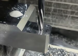
The reaming process includes workpiece clamping, pre-drilling or boring, tool selection, reamer alignment, controlled cutting, chip removal, lubrication, and inspection. Each step affects final hole quality.
Workpiece Clamping
Workpiece clamping keeps the component stable during reaming. Even small vibration can cause chatter, tapered holes, poor roundness, or visible tool marks.
For tight-tolerance holes, the fixture should hold the part rigidly without bending thin walls or damaging functional surfaces. Total indicated runout should be controlled as much as possible, especially when targeting tolerances around ±0.005 mm.
Soft jaws, hydraulic clamps, precision vises, custom fixtures, tailstocks, or steady rests may be used depending on part geometry. Stable workholding is especially important for long parts, thin-walled components, and high-value precision parts.
Pre-Drilling Or Boring
Pre-drilling or boring creates the hole that the reamer will finish. The pre-hole is usually machined slightly smaller than the final required diameter, leaving a controlled allowance for reaming.
A common allowance range is about 0.15–0.50 mm in diameter. For example, a Ø10 mm precision hole may leave approximately 0.15–0.25 mm for reaming, depending on material and tool recommendation.
The pre-hole should also have acceptable straightness, roundness, and alignment. If the pre-hole is badly misaligned, reaming will generally follow that error rather than completely correcting it.
Tool Selection
Tool selection determines whether the reamer can meet the required hole tolerance, surface finish, tool life, and production volume. Reamer material, flute geometry, coating, diameter, and holder type must match the application.
HSS reamers may be suitable for prototypes, low-volume work, and softer materials. Carbide reamers provide better rigidity, wear resistance, and consistency in production or harder materials.
For abrasive materials, composites, or high-volume runs, coated carbide or PCD reamers may provide longer tool life. The best tool should be selected according to material hardness, hole depth, tolerance, chip behavior, and batch size.
Reamer Setup And Alignment
Reamer setup and alignment are critical because reaming follows the existing hole path. Even small spindle misalignment or tool runout can cause taper, oversize holes, poor roundness, or chatter.
Precision collets, shrink-fit holders, hydraulic holders, or floating holders may be used depending on machine condition and tolerance requirements. Precision toolholders can help keep runout below 0.005 mm in demanding applications.
Floating holders are useful when there is minor spindle-to-hole misalignment. They allow limited radial compensation and can reduce binding, especially in reaming operations where the tool must follow an existing hole.
Reaming Operation
The reaming operation should use lower cutting speeds than drilling and a steady, controlled feed. Reaming usually works best with consistent feed because hesitation can leave marks on the hole wall.
For carbide reamers, typical cutting speeds may range from 40–80 m/min depending on material. For HSS reamers, speeds are often lower, commonly around 10–20 m/min for many general materials.
Feed rates commonly range from 0.05–0.20 mm/rev, though exact values depend on tool diameter, material, flute design, and hole type. Excessive speed can increase wear, while too low a feed may cause rubbing and chatter.
Chip Removal And Lubrication
Chip removal and lubrication are essential for stable reaming because chips trapped in the hole can scratch the surface, damage the tool, or change the final diameter. This is especially important in blind holes and deep holes.
For holes deeper than 2×D or 3×D, through-tool coolant, high-pressure coolant, cutting oil, or peck reaming may be needed. In some deep-hole applications, coolant pressure above 20–30 bar can improve chip evacuation.
Lubrication reduces heat and friction. It also improves tool life, surface finish, and dimensional consistency. Poor lubrication may cause built-up edge, tool chipping, surface scoring, and rapid tool wear.
Inspection
Inspection confirms whether the reamed hole meets the required size, surface finish, and functional fit. Common inspection tools include plug gauges, bore gauges, air gauges, micrometers, CMMs, and surface roughness testers.
For production holes, go/no-go plug gauges are often used for fast fit verification. For high-precision parts, bore measurement and surface roughness inspection may be required.
Inspection should match the drawing requirement. A hole used for a loose fastener may need only basic checking, while aerospace, medical, hydraulic, or bearing-related holes may require documented dimensional and surface verification.
What Are The Main Types Of Reamers?
The main types of reamers include hand reamers, machine reamers, straight-flute reamers, helical-flute reamers, floating reamers, adjustable reamers, carbide reamers, and shell reamers. Each type is designed for different hole conditions, materials, and production needs.
Choosing the wrong reamer can cause poor finish, oversize holes, chatter, chip packing, or short tool life. Tool selection should consider hole depth, hole type, tolerance, material, machine rigidity, and production volume.
The table below summarizes common reamer types and their typical uses.
| Reamer Type | Application Scenario | Suitable Materials | Key Advantages |
| Hand Reamer | Manual finishing, toolmaking, repair, prototyping | General-purpose materials | Low cost and flexible for low-volume use |
| Straight-Flute Machine Reamer | Rigid setups and short-chip materials | Cast iron, brass, bronze | Simple geometry and stable sizing |
| Helical-Flute Reamer | Through-holes and deep-hole reaming | Steel, aluminum, ductile metals | Better chip evacuation and reduced chatter |
| Floating Reamer | Minor spindle or hole misalignment | Most machinable metals | Self-aligning support and improved consistency |
| Adjustable Reamer | Custom diameter finishing and repair work | General metals | Adjustable size range and reusable design |
| Carbide Reamer | Long runs and hard materials | Hardened steel, stainless steel, titanium | Long tool life, rigidity, and wear resistance |
| PCD Reamer | Abrasive materials and high-volume production | Aluminum alloys, composites, non-ferrous materials | High wear resistance and stable surface finish |
| Shell Reamer | Large bore finishing and modular systems | Large metal parts | Replaceable cutting head and cost efficiency |
How To Choose The Right Reamer?
The right reamer is chosen according to material, hole diameter, tolerance, stock allowance, hole type, chip evacuation direction, toolholder, and production volume. A reamer should match both the hole geometry and the machining environment.
Material And Hole Diameter
Material and hole diameter directly affect reamer material, tool rigidity, and cutting parameters. Softer metals such as aluminum, brass, and mild steel can often be reamed with HSS or carbide tools depending on volume.
Medium-hard steels and stainless steels usually require better heat resistance and wear control. Cobalt HSS, coated HSS, or solid carbide reamers may be selected depending on tolerance and batch size.
Hard alloys, titanium, Inconel, composites, and abrasive materials often require carbide, coated carbide, or PCD tools. For micro holes below Ø1 mm, fine-grain carbide and specialized geometry may be required to maintain tool stiffness and dimensional control.
Stock Removal And Tool Life
Stock removal strongly affects tool life, surface finish, and hole accuracy. The recommended stock allowance should be large enough to create a clean chip but small enough to avoid heavy cutting load.
A typical reaming allowance is about 0.15–0.50 mm in diameter. For aluminum, 0.25–0.35 mm may work well in many cases. For steels, 0.30–0.50 mm is often used. For titanium and heat-resistant alloys, a smaller controlled allowance may help reduce tool stress.
Too much stock can cause chatter, deflection, heat, and premature tool wear. Too little stock can cause rubbing instead of cutting, which leads to poor surface finish and faster edge failure.
Hole Type And Flute Direction
Hole type determines which flute direction is most suitable. Through-holes usually benefit from spiral or helical flutes that help move chips forward and out of the hole.
Blind holes require more careful chip control because chips cannot exit through the bottom. Straight-flute or reverse-helix reamers may be used to pull chips away from the blind end and reduce chip packing.
For deep blind holes, peck reaming, high-pressure coolant, or through-tool coolant may be needed. Chip buildup at the bottom of a blind hole can scratch the surface or break the tool.
Holder Type And Runout Control
Holder type affects reamer alignment, runout, and final hole quality. Precision collets, hydraulic holders, shrink-fit holders, and floating holders are commonly used depending on the machine and tolerance requirement.
Precision holders provide high concentricity and are useful for stable CNC machines. In demanding reaming operations, tool runout should be minimized because radial error directly affects roundness and hole size.
Floating holders are useful when minor misalignment exists between the spindle and the pre-hole. They compensate for small axial or radial errors and reduce tool binding during the finishing cut.
What Are Typical Reaming Applications?
Typical reaming applications include aerospace actuator housings, automotive suspension parts, medical implants, pump housings, bearing seats, hydraulic valve bodies, jigs, fixtures, and precision alignment holes. The process is used whenever hole quality directly affects assembly, motion, sealing, or positioning.
Reaming is often selected when drilling is not accurate enough, but honing or grinding would be too slow or expensive. It provides a practical balance between precision, speed, and cost.
The tolerance requirement depends on the application. General cnc machining holes may use looser tolerances, while aerospace or medical parts may require much tighter control.
| Industry | Typical Components | Reaming Purpose | Typical Tolerance Level |
| Aerospace | Turbine casings, actuator housings, structural fittings | Precise alignment and critical assembly fits | ±0.005 mm or tighter |
| Automotive | Suspension arms, pistons, gearbox parts | Press fits, shaft alignment, and repeatable assembly | ±0.01 mm to ±0.005 mm |
| Medical Devices | Orthopedic implants, surgical instruments | Smooth holes and precision biocompatible assemblies | ±0.003 mm to ±0.005 mm |
| Pumps And Bearings | Pump housings, bearing seats, shaft supports | Shaft alignment and reduced wear | Around ±0.01 mm |
| Hydraulic Systems | Valve bodies, manifolds, sealing holes | Smooth flow and sealing reliability | Application-dependent |
| General Machining | Jigs, fixtures, dies, precision holes | Repeatable hole quality and alignment | Around ±0.01 mm or per drawing |
What Are The Advantages Of Reaming?
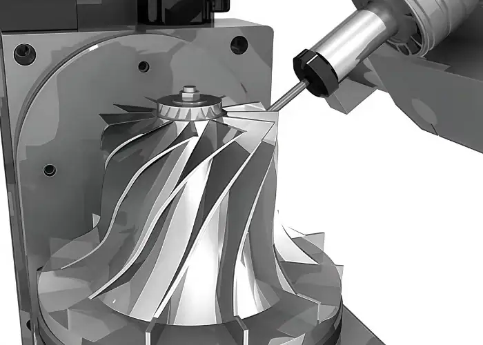
The advantages of reaming include high dimensional accuracy, smooth surface finish, good repeatability, short cycle time, and efficient production of precision holes. It is often faster and more economical than honing or grinding for many industrial hole-finishing tasks.
High Dimensional Accuracy
Reaming can achieve high dimensional accuracy because the tool removes a small and controlled amount of material. In precision applications, tolerances around ±0.005 mm are possible with suitable machines, tools, and inspection control.
This makes the process valuable for pins, bushings, bearing seats, shaft holes, and assembly features that require repeatable fit.
Accuracy depends on the full setup. Poor drilling, excessive tool runout, unstable clamping, or worn cutting edges can prevent the process from reaching the expected tolerance.
Excellent Surface Finish
Reaming can produce smooth hole surfaces, commonly around Ra 0.2–0.8 µm depending on conditions. A smooth finish reduces friction, improves sealing, and supports better sliding or rotating contact.
This is useful for hydraulic components, medical instruments, bearing bores, automotive parts, and precision alignment holes.
Surface finish is affected by tool sharpness, speed, feed, coolant, chip evacuation, and material behavior. When these factors are controlled, reaming can often eliminate the need for additional polishing.
Efficient Production Cycle
Reaming is efficient because it removes only a small amount of material after drilling or boring. Compared with boring or honing, it can be faster for many production holes.
In stable batch production, the process can support short cycle times and consistent results. This makes it suitable for automotive, aerospace, general machining, and fixture manufacturing.
However, cycle time should not be reduced by using excessive speed or poor lubrication. Over-aggressive parameters may shorten tool life and reduce hole quality.
Strong Repeatability
Reaming provides strong repeatability because the reamer’s geometry helps control hole size across multiple parts. Once the process is stable, the same toolpath can produce consistent holes over a production run.
Repeatability is important for assembly reliability. If a dowel pin hole or bearing seat varies too much between parts, assembly force and part function may change.
Tool wear should still be tracked. As the reamer edge wears, hole size and surface finish can drift, so inspection frequency should match the tolerance risk.
What Are The Limitations Of Reaming?
The limitations of reaming include sensitivity to pre-hole quality, limited ability to correct location errors, chip evacuation problems in blind holes, tool wear in abrasive materials, and risk of chatter or oversize holes. It is a finishing process, not a heavy correction process.
Limited Correction Ability
Reaming has limited correction ability because it follows the existing hole path. It can improve size and finish, but it does not reliably correct major hole-position error.
If a hole is significantly off-location, boring or another correction process may be needed first. Reaming should be used after the hole is already close to the required geometry.
This is why good drilling and boring practice matters. The final reamed hole quality depends heavily on the accuracy of the previous operation.
Tool Wear In Difficult Materials
Tool wear can become a problem when reaming abrasive or heat-resistant materials such as titanium, Inconel, composites, fiberglass, and some hardened steels. As the cutting edge wears, the surface finish and hole size may degrade.
HSS reamers may lose sharpness quickly in difficult materials. Carbide, coated carbide, or PCD tools are often better choices for production or abrasive applications.
Coolant and cutting parameters also affect wear. Insufficient lubrication or excessive speed can shorten tool life and cause heat-related defects.
Chip Evacuation In Blind Holes
Chip evacuation is difficult in blind holes because chips cannot exit through the bottom. If chips collect at the blind end, they can scratch the hole surface, damage the reamer, or cause tool breakage.
Blind-hole reaming may require reverse-helix tools, peck cycles, through-tool coolant, cutting oil, or compressed air assistance. The correct method depends on material, hole depth, and tolerance.
For holes deeper than 1.5×D to 3×D, chip control becomes increasingly important. Poor evacuation can quickly turn a precision finishing operation into a scrap risk.
Misalignment Sensitivity
Reaming is sensitive to misalignment between the spindle, tool, and pre-hole. Even small radial error can cause lobing, taper, bell-mouth, or oversize holes.
Floating holders can help compensate for minor misalignment. Precision collets or shrink-fit holders can reduce runout in rigid, accurate setups.
The best approach is to control alignment from the start. Proper drilling, rigid fixturing, spindle inspection, and toolholder selection all help stabilize the reaming result.
How To Optimize The Reaming Process?
The reaming process is optimized by controlling pre-hole allowance, cutting speed, feed rate, tool runout, coolant, chip evacuation, tool wear, and inspection frequency. Optimization should improve repeatability rather than only reduce cycle time.
Speed And Feed Recommendations
Speed and feed should be selected according to reamer material, workpiece material, hole diameter, and required finish. Reaming is usually performed at lower speed than drilling but with a steady feed.
For carbide reamers, typical cutting speeds may range from 40–80 m/min, with feeds around 0.05–0.15 mm/rev in many precision applications. For HSS reamers, cutting speeds may range from 10–20 m/min, with feeds around 0.03–0.10 mm/rev.
These values are starting points. Tool supplier recommendations should be followed for exact applications, especially for titanium, stainless steel, hardened steel, composites, or high-volume production.
Lubrication And Coolant
Lubrication and coolant reduce friction, heat, tool wear, and chip damage during reaming. They are essential for maintaining hole size and surface finish.
Through-tool coolant or high-pressure coolant is recommended for deep holes and difficult materials. Coolant pressures above 20–30 bar may improve chip evacuation in deep or blind-hole conditions.
Cutting oil may improve finish in some steels and stainless steels, while emulsions may improve cooling and chip flushing. The coolant type should match the material and tool coating.
Recommended Reaming Allowances
Recommended reaming allowance depends on hole diameter, material, and tool rigidity. Too much allowance increases cutting force, while too little causes rubbing.
| Hole Diameter Range | Recommended Stock To Leave For Reaming | Notes |
| Ø6–10 mm | 0.15–0.25 mm | Suitable for most materials with HSS or carbide tools |
| Ø10–20 mm | 0.20–0.35 mm | Good balance between chip formation and size control |
| Ø20–50 mm | 0.30–0.50 mm | Requires stable setup and sufficient tool rigidity |
| Deep Holes Above 3×D | Application-specific | Coolant pressure and chip evacuation become critical |
| Tight-Tolerance Holes | Follow tool supplier data | Allowance must be consistent along the full depth |
Avoiding Common Reaming Errors
Common reaming errors include excessive feed, dull tools, unstable clamping, poor lubrication, incorrect allowance, and tool misalignment. Each error can directly affect hole size, roundness, and surface finish.
Excessive feed can cause deflection, chatter, and poor circularity. A dull reamer can create heat, burn marks, taper, and rough surfaces. Poor clamping can produce vibration and inconsistent diameters.
Insufficient coolant can cause chip jamming, built-up edge, surface scratches, and tool chipping. In deep or blind holes, coolant and chip evacuation should be treated as part of the process design, not an afterthought.
Reaming Vs Drilling Vs Boring
Reaming, drilling, and boring are different hole-machining operations with different purposes. Drilling creates the initial hole, boring enlarges or corrects hole geometry, and reaming finishes the hole to improve size and surface quality.
| Process | Main Purpose | Typical Strength | Main Limitation |
| Drilling | Creates the initial hole | Fast material penetration | Lower accuracy and rougher finish |
| Boring | Enlarges and corrects hole geometry | Corrects alignment and size | Slower than drilling and reaming |
| Reaming | Finishes hole size and surface | High accuracy and smooth finish | Follows existing hole path |
| Honing | Improves surface and geometry further | Very fine finish and roundness | Slower and higher cost |
FAQs
Why Use A Reamer Instead Of A Drill?
A reamer is used instead of a drill when the hole needs tighter tolerance, better roundness, and smoother surface finish. Drilling may commonly hold around ±0.1 mm with a rougher surface, while precision reaming can reach around ±0.005 mm and Ra 0.2–0.8 µm under controlled conditions. This makes reaming suitable for press-fit holes, dowel pins, bearing seats, and alignment sleeves.
What Is The Difference Between Boring And Reaming?
Boring is used to enlarge and correct a hole’s position, straightness, and geometry, while reaming is used to finish a prepared hole to final size and surface quality. Boring is more flexible for correcting misalignment, but it is usually slower. Reaming is faster and more repeatable for finishing holes that are already close to the required diameter and axis.
What Is The Formula For Reaming Feed And RPM?
The feed rate for reaming is calculated as feed per revolution multiplied by spindle speed. The common formula is: Feed Rate = Feed Per Rev × RPM. Spindle speed can be calculated as RPM = (1000 × Vc) / (π × D), where Vc is cutting speed in m/min and D is tool diameter in mm. Typical feeds may range from 0.03–0.15 mm/rev depending on tool and material.
What Is CNC Reaming?
CNC reaming is a programmed hole-finishing operation performed on a CNC milling machine, turning center, or machining center. The machine controls spindle speed, feed rate, tool position, and depth to finish pre-drilled or bored holes. It is commonly used for precision holes in aerospace, automotive, medical, hydraulic, and industrial components where size consistency and surface finish are important.
Conclusion
Reaming is a practical and reliable finishing process for producing accurate, round, and smooth holes after drilling or boring. Its main value comes from controlled material removal, stable tool geometry, fine surface finish, and repeatable hole size. Successful reaming still depends on correct pre-hole allowance, rigid clamping, proper reamer selection, alignment control, coolant delivery, chip evacuation, and inspection.
At TiRapid, we provide precision CNC machining and manufacturing services for custom metal and plastic components. Our capabilities support drilling, boring, reaming, milling, turning, dimensional inspection, DFM review, and surface finishing for prototypes and low-volume production requiring accurate holes, controlled fits, reliable assembly quality, and consistent manufacturing performance.
















