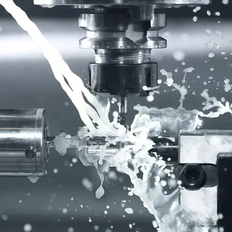
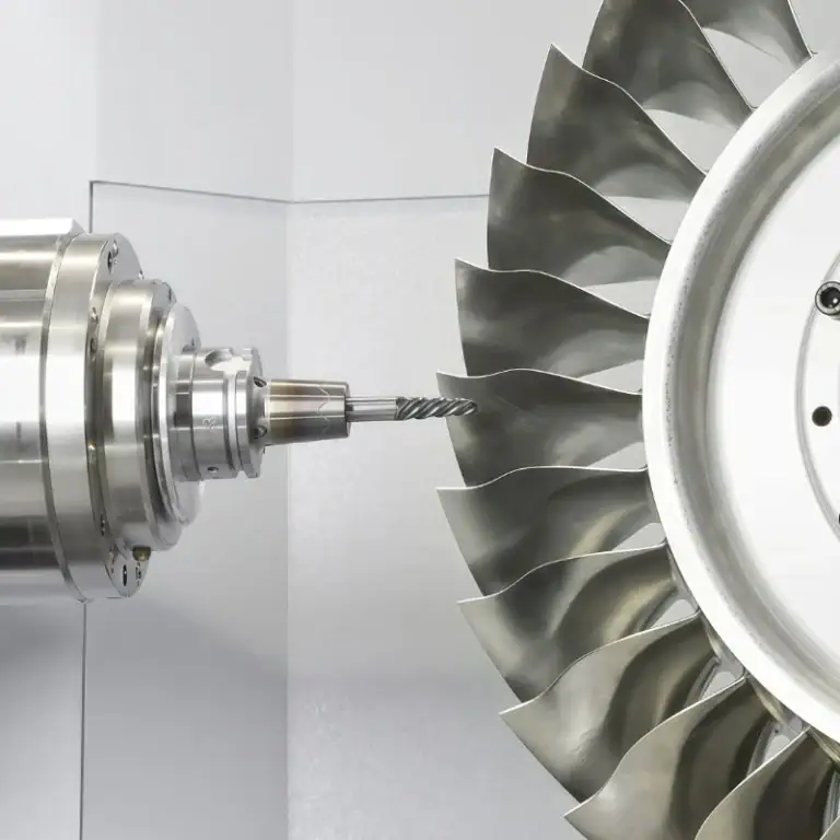
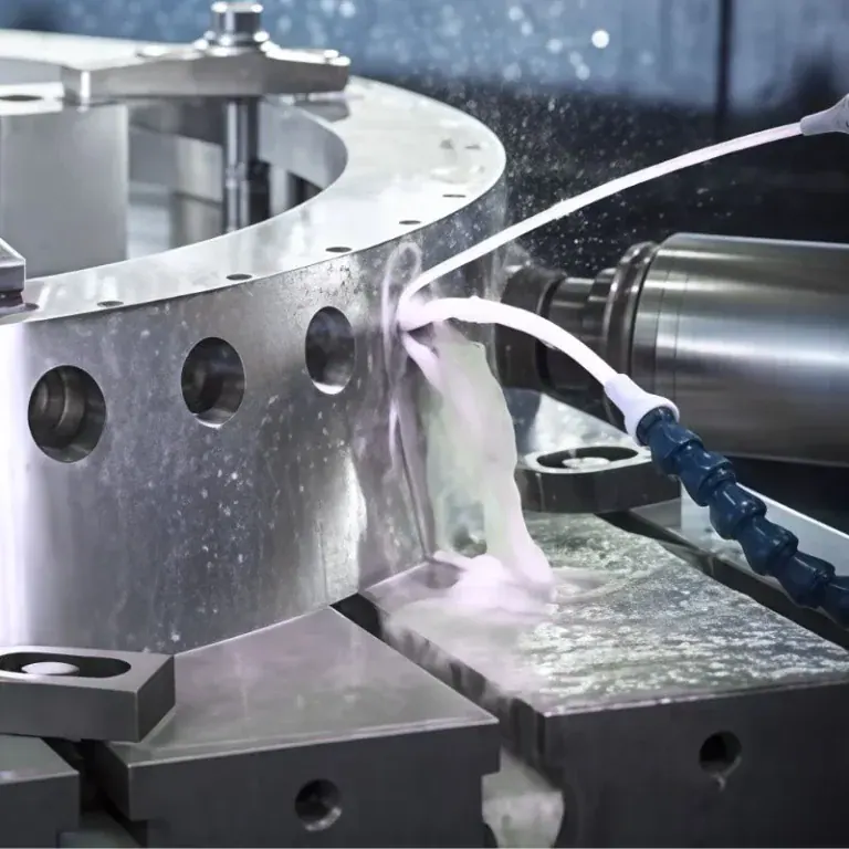
In metal part design, fillets are seemingly simple but highly important structural features. Whether a component is made from aluminum alloy, stainless steel, or carbon steel, corner geometry can affect tool movement, material stress distribution, and final product quality during CNC milling, turning, and other metal machining processes. Proper fillet design not only improves structural performance but also reduces machining difficulties, lowers production costs, and extends component service life. Therefore, fillets should be an important consideration when developing metal machining solutions.
What Are Fillets in Metal Part Design?
Basic Concept of a Fillet
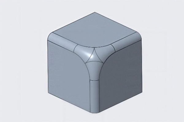
A fillet is a rounded transition between two intersecting surfaces. It replaces a sharp corner or right angle with a smooth curve of a specific radius. In mechanical components, fillets are commonly used on external edges, internal grooves, cavities, stepped connections, and transitions between different cross-sections.
Compared with sharp corners, fillets improve component geometry, reduce localized stress concentration, and allow cutting tools to follow machining paths more smoothly.
Differences Between Internal and External Fillets
Internal fillets are commonly found in grooves, cavities, and connecting areas between holes and slots. Their radii directly affect CNC milling tool selection. If an internal fillet is too small, manufacturers may need smaller-diameter cutting tools, increasing machining time and tool wear.
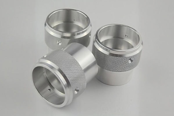
External fillets are mainly used on component edges and protruding structures. They help eliminate sharp edges, improve handling safety, and create smoother transitions between surfaces. Their dimensions should be determined according to functional requirements, assembly conditions, and machining methods.
How Does Proper Fillet Design Reduce Metal Machining Costs?
Reducing Tool Changes and Machining Time
During CNC milling, cutting tool diameter is often limited by the internal corner radius of a component. Extremely small internal fillets may require smaller cutting tools, which generally have lower rigidity and material removal efficiency than larger tools.
If the internal fillet radius can be increased without affecting component functionality, manufacturers may use larger milling cutters. This improves material removal efficiency, reduces tool changes, and shortens overall machining cycles.
Reducing Tool Wear and Breakage Risks
Small-radius fillets often require smaller cutting tools. When machining depths are considerable or the material has high hardness, these tools are more likely to experience vibration, excessive wear, or even breakage.
Appropriate fillet dimensions help improve cutting conditions and reduce tool loading. This can minimize tool consumption and reduce machine downtime during production.
Improving Consistency in Mass Production
For metal components manufactured in large quantities, overly complicated corner structures can increase machining path complexity and process control difficulties.
Proper fillet design simplifies tool movement and eliminates unnecessary finishing operations. As a result, manufacturers can maintain more consistent dimensions and surface quality across different production batches.
How Do Fillets Affect Structural Strength and Component Service Life?
Reducing Stress Concentration
When a metal component contains sharp internal corners, external loads tend to concentrate around these areas, creating localized stress concentration. In components exposed to repeated bending, tensile forces, or vibration, sharp corners may become starting points for fatigue cracks.
Adding an appropriate fillet radius creates a smoother transition for load transfer and reduces local stress peaks. This improves the component’s resistance to fatigue failure.
Reducing the Risk of Cracks and Structural Failure
During long-term operation, metal components may experience impact, vibration, and cyclic loading. Sharp corners can create weak areas where small cracks develop and gradually propagate, eventually causing component failure.
Proper fillet transitions improve local geometry and reduce the risk of crack initiation. This is particularly important for mechanical connectors, support structures, transmission components, and load-bearing parts.
Improving Surface Quality and Assembly Performance
Fillets can also help reduce burrs and sharp edges, minimizing the amount of additional deburring and edge-finishing work required.
During assembly, appropriately designed fillets can facilitate component positioning and reduce edge scraping or localized impact. However, fillets should not be enlarged without considering functional requirements. For components requiring precise contact or positioning, designers must ensure that fillets do not interfere with mating surfaces, locating features, or assembly clearances.
How to Select the Right Fillet Radius for Metal Parts
Determine Dimensions Based on CNC Cutting Tools
Designers should consider commonly available milling cutter diameters and machining equipment capabilities when specifying internal fillets.
For grooves without special functional requirements, larger internal radii are generally preferable because they avoid difficult machining operations involving extremely small-radius tools.
Adjust Fillet Dimensions According to Material and Loading Conditions
Different metal materials have different strength, hardness, and machinability characteristics. Aluminum alloys generally offer good machinability, while stainless steel requires greater attention to cutting resistance and work hardening.
For components exposed to heavy loads or repeated cyclic stress, fillet dimensions should be determined through structural analysis and, when necessary, finite element analysis rather than relying solely on machining convenience.
Balance Manufacturing Costs and Functional Requirements
Larger fillets are not always better. Excessively large radii may affect component geometry, installation space, and the fit of adjacent structures.
During the design stage, engineers should consider functional requirements, material properties, cutting tool dimensions, dimensional tolerances, and subsequent assembly requirements to achieve a practical balance between manufacturability and performance.
How Does TIRAPID Improve Component Quality Through Optimized Metal Machining Solutions?
For CNC metal machining projects, an effective manufacturing solution must do more than meet drawing dimensions. It should also evaluate whether the component structure is suitable for efficient production. TIRAPID focuses on metal machining solutions and can help evaluate machining processes according to component geometry, material types, and manufacturing requirements.
During project development, factors such as fillet radius, internal cavity geometry, wall thickness, and machining tolerances can all influence the final manufacturing results. Evaluating these factors early in the design and machining stages helps reduce unnecessary operations, improve production efficiency, and deliver metal components that meet application requirements.
For businesses requiring custom-machined components, communicating with an experienced manufacturing supplier at an early stage helps identify potential design issues before production begins. This can prevent additional machining expenses caused by poor structural design.
Conclusion
Although fillets are relatively small geometric features in metal components, they can significantly influence CNC machining efficiency, tooling costs, structural strength, and product service life.
Proper fillet design helps simplify machining operations, reduce stress concentration, and improve long-term component reliability.
During metal part development, integrating manufacturing considerations into structural design and selecting suitable fillet radii according to actual application requirements are essential steps toward achieving high-quality, cost-effective metal machining.