Injection molding and plastic extrusion both heat plastic materials and shape them into repeatable products. However, they produce very different results. Injection molding creates individual three-dimensional parts inside a closed mold, while extrusion continuously produces long profiles with a consistent cross-section.
This guide explains the injection molding vs extrusion process, including how each method works, their tooling and production costs, design requirements, suitable materials, common applications, and selection criteria. Understanding these differences can help you choose a practical process before investing in tooling or preparing a part for production.
What Are Injection Molding And Plastic Extrusion?
Injection molding and extrusion are two major plastic manufacturing processes. Both commonly use plastic pellets, a heated barrel, and a rotating screw, but their forming methods are different. Injection molding fills a closed cavity during repeated cycles, while extrusion pushes material continuously through an open die.
How Injection Molding Works
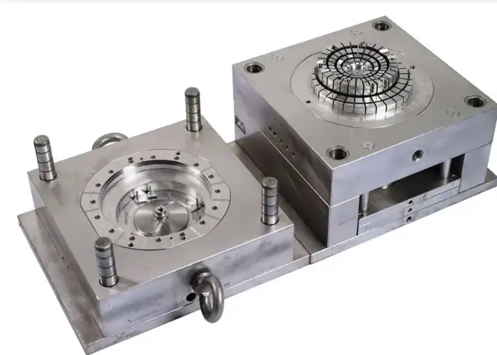
The injection molding process begins when plastic pellets enter a heated barrel through a hopper. A rotating screw moves the material forward while heat and shear soften it into a controlled melt. The screw then moves forward and injects the plastic into a closed mold under pressure.
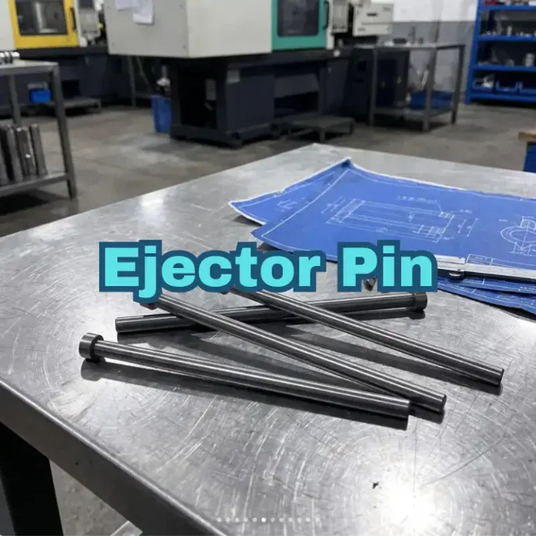
The molten plastic fills the mold cavity and forms the required geometry. Holding pressure helps compensate for material shrinkage as the part begins to cool. Once the material becomes stable enough, the mold opens and ejector pins, plates, or other mechanisms remove the finished part.
The mold then closes, and the cycle begins again. Cores, cavities, inserts, slides, lifters, gates, cooling channels, and surface textures can be incorporated into the tooling. This makes injection molding suitable for repeatable housings, clips, covers, brackets, connectors, and other detailed three-dimensional parts.
How Plastic Extrusion Works
Plastic extrusion also starts with pellets entering a heated barrel. A rotating screw transports, compresses, melts, and mixes the material. Instead of injecting the melt into a closed cavity, the extruder continuously forces it through a shaped opening called an extrusion die.
The material leaving the die has the required cross-sectional shape. It then passes through cooling, sizing, calibration, or pulling equipment so the profile can stabilize. The continuous product may be cut into specified lengths, wound onto rolls, or prepared for secondary processing.
Extrusion can produce simple rods and tubes as well as hollow, semi-hollow, multi-channel, or detailed custom profiles. The cross-section may be complex, but it normally remains consistent along the product’s length. Typical outputs include pipes, seals, rails, sheets, films, channels, and cable insulation.
Injection Molding vs Extrusion: Key Differences
The main injection molding vs extrusion difference is the type of geometry produced. Injection molding creates separate parts whose shape can change in every direction. Extrusion creates a continuous product whose length can vary but whose cross-section remains substantially unchanged.
| Comparison | Injection Molding | Plastic Extrusion |
| Production method | Repeated molding cycles | Continuous production |
| Typical output | Individual parts | Continuous profiles |
| Main tooling | Closed mold with cores and cavities | Open extrusion die |
| Suitable geometry | Complex three-dimensional parts | Constant cross-section products |
| Local features | Can be integrated into the mold | Usually require secondary operations |
| Surface detail | Textures, logos, and molded details | Mainly controlled by the die surface |
| Typical strength | Complex part integration | Efficient long-profile production |
| Common products | Housings, clips, covers, connectors | Tubes, seals, rails, sheets, channels |
Part Geometry And Product Form
Injection molding is suitable when a part needs a complete three-dimensional form. The mold can create ribs, bosses, snap fits, openings, textured surfaces, mounting features, local wall changes, and other details within the boundaries of practical mold construction.
Extrusion is suitable when the same shape must continue along a product’s length. A profile may include internal chambers, grooves, fins, lips, or cable channels, but the die cannot directly create a hole that appears only at one location or a pocket that stops halfway along the part.
These local features can be added after extrusion through cutting, drilling, punching, welding, forming, or CNC machining. Therefore, engineers should separate the repeated cross-sectional geometry from the localized features when deciding which process is more efficient.
Tooling And Production Method
An injection mold normally contains two or more mold halves, a cavity, a core, a feed system, vents, cooling channels, and an ejection system. More demanding parts may also require slides, lifters, unscrewing mechanisms, inserts, or multiple cavities.
An extrusion die does not form the complete length of the product. It controls the cross-section as plastic flows continuously through it. The complete production system may also need calibrators, cooling tanks, pullers, cutters, rollers, or winding equipment.
Because the tool structures perform different functions, their costs should not be compared without considering the entire production line. Injection tooling is often more complex, while extrusion may require substantial downstream equipment to control profile size, straightness, cooling, and handling.
Accuracy, Surface Finish, And Repeatability
Injection molding can reproduce detailed mold surfaces, logos, textures, parting lines, and functional features across large production quantities. Dimensional consistency depends on mold quality, material shrinkage, processing conditions, cooling balance, machine control, and part design.
Extrusion can provide stable cross-sectional dimensions and continuous surface quality, but the profile remains unsupported after leaving the die. Die swell, cooling rate, pulling speed, material distribution, and gravity can affect width, wall thickness, straightness, twist, and flatness.
Neither process automatically guarantees tight tolerances. Critical dimensions should be identified according to function. Injection-molded parts may require process optimization, while extruded products may need calibration, straightening, cutting, or secondary machining to meet assembly requirements.
Materials And Material Flow
Both processes commonly use thermoplastics, including grades of ABS, PP, PE, PC, PA, PVC, POM, PMMA, and TPE. However, material families contain different grades developed for specific molding or extrusion conditions.
Injection molding generally benefits from material that can flow through runners, gates, thin walls, and detailed cavities before cooling. Extrusion requires stable output as the melt leaves the die, so melt strength, die swell, cooling behavior, and dimensional stability are important.
A material that is available for both processes may still use different formulations, molecular weights, additives, or melt-flow properties. Engineers should select the exact processing grade rather than assuming that every grade within one polymer family works equally well for injection molding and extrusion.
Injection Molding vs Extrusion Cost
Cost depends on more than the price of the mold or extrusion die. A useful comparison includes tooling, material, setup, cycle time, production quantity, secondary processing, inspection, scrap risk, packaging, and design changes.
Initial Tooling And Setup Cost
Injection molds can be expensive because they must control filling, cooling, venting, separation, and ejection. Cost increases with part size, cavity count, surface finish, mold material, tight tolerances, side actions, threads, inserts, and complicated undercuts.
An extrusion die is often structurally simpler because it primarily controls one cross-section. However, hollow profiles, multi-material products, thin walls, unbalanced shapes, or demanding dimensions can still require advanced die engineering, calibration tooling, and repeated die corrections.
For prototypes or changing designs, early tooling investment can create risk. CNC machining, 3D printing, vacuum casting, or standard extruded profiles may be more practical until geometry and material requirements are stable.
Cycle Time And Production Volume
Injection molding produces one or more finished parts during each cycle. Higher-cavity molds can increase output, but they also raise tooling complexity and require balanced filling and cooling. As production quantity grows, the initial mold cost is distributed across more parts.
Extrusion runs continuously, making it efficient for pipes, seals, films, sheets, and long profiles. Output is often evaluated by length or material throughput rather than by the number of molding cycles.
Production volume alone does not determine the better process. A million complex housings still require injection molding, while a much smaller quantity of a long constant-section tube may still require extrusion. Geometry must be evaluated before unit cost.
Secondary Processing And Total Manufacturing Cost
Injection molding can integrate clips, bosses, ribs, openings, textures, and assembly features into one molded component. This may reduce machining and assembly, although gate removal, insert loading, printing, coating, or part assembly may still be necessary.
Extruded profiles are normally cut to length and may require holes, end features, slots, windows, threads, notches, formed bends, welded joints, or machined interfaces. These operations can make an inexpensive profile more costly as a finished component.
The correct comparison is therefore the total cost of a usable part. A higher-priced mold may reduce downstream operations, while a simpler extrusion die may be economical only when the product needs limited local modification.
Design Requirements For Each Process
Injection molding and plastic extrusion follow different design rules. A design that works well for one process cannot always be transferred directly to the other. Early design-for-manufacturing review helps prevent unstable filling, distortion, unnecessary tooling features, and excessive secondary work.
Injection Molding Design Rules
Consistent wall thickness helps plastic fill and cool more evenly. Sudden thick sections may cool slowly and increase the risk of sink marks, voids, internal stress, or warpage. Ribs and bosses can add stiffness and support fasteners without making the complete wall excessively thick.
Draft angles help molded parts release from the tool. Rounded corners improve flow and reduce stress concentration, while carefully designed ribs, bosses, and gussets support strength. Undercuts may require slides, lifters, collapsible cores, or design changes.
Gate position, parting lines, ejector locations, weld lines, venting, and cosmetic surfaces should also be considered. These details connect part design to mold design and can directly affect appearance, strength, cycle stability, and tooling cost.
Plastic Extrusion Design Rules
An extruded product must maintain a continuous cross-section. Changes to the product should normally occur through cut length or secondary operations rather than through the extrusion die itself.
Balanced wall thickness and symmetrical material distribution help the melt flow more evenly. Large differences between thick and thin sections may cause uneven cooling, distortion, unstable pulling, or dimensional variation. Rounded corners also support material flow and reduce difficult die conditions.
Hollow chambers, fins, channels, and flexible lips are possible, but each feature affects pressure, die design, cooling, and calibration. The supplier should review the profile as a complete flow system rather than evaluating each dimension independently.
Tolerances, Shrinkage, And Dimensional Control
Plastic dimensions change as material cools. The amount and direction of shrinkage depend on the resin, fillers, flow direction, wall thickness, processing conditions, and part geometry.
Injection molding dimensions are influenced by cavity size, packing pressure, cooling balance, gate position, and material orientation. Extrusion dimensions are influenced by die shape, die swell, drawdown, calibrator size, cooling, line speed, and profile support.
Applying tight tolerances to every dimension increases manufacturing difficulty without always improving performance. Functional interfaces, sealing areas, assembly features, and alignment dimensions should receive priority, while noncritical surfaces can use practical process tolerances.
Materials, Parts, And Applications
Many thermoplastics can be processed by both methods, but the most suitable choice depends on product shape, mechanical performance, chemical exposure, appearance, regulatory requirements, and the selected manufacturing grade.
Common Materials For Injection Molding And Extrusion
Injection molding commonly uses ABS for housings, PP for flexible or chemical-resistant parts, PC for impact-resistant components, PA for mechanical parts, and POM for low-friction features. Filled materials can improve stiffness, strength, wear resistance, or dimensional stability.
Extrusion frequently uses PE and PP for tubes, films, and sheets; PVC for pipes and construction profiles; TPE for flexible seals; and PC, PMMA, ABS, or engineering plastics for transparent, protective, or structural profiles.
The material name alone is not sufficient for production. Moisture control, drying, melt temperature, cooling, additives, colorants, reinforcement, and recycled content can all affect processing and final part quality.
Parts Best Suited For Injection Molding
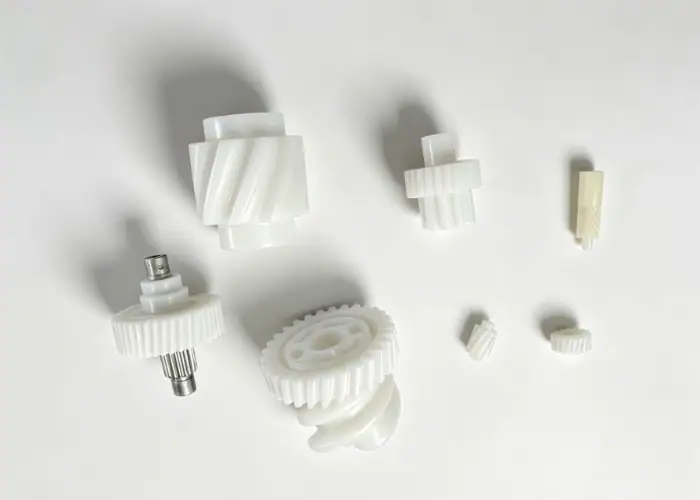
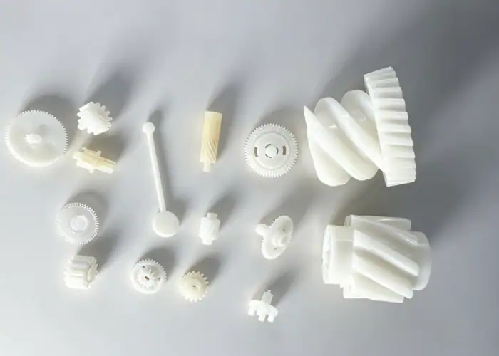
Injection molding is ideal for individual parts with complex geometry and integrated functions. Examples include electronic housings, appliance components, medical device bodies, automotive interior parts, clips, connectors, gears, covers, brackets, and consumer product enclosures.
The process is especially valuable when one molded part can replace several machined or assembled pieces. Snap fits, locating features, fastener bosses, cable guides, labels, and cosmetic textures can often be integrated into the design.
Injection molding is generally most economical after the design is stable and the expected quantity can justify tooling. Prototypes and bridge production may use machined plastic, 3D printing, vacuum casting, or rapid tooling before full production molds are released.
Products Best Suited For Plastic Extrusion
Plastic extrusion is suitable for products that maintain one cross-section over a continuous length. Common examples include pipes, flexible tubes, medical tubing, weatherstripping, window profiles, edge trims, guide rails, cable channels, sheets, films, and protective sleeves.
The process can also create multi-chamber profiles, co-extruded seals, rigid-soft combinations, or profiles containing functional grooves and mounting channels. The design must still remain continuous along the extrusion direction.
After extrusion, products can be supplied in long lengths, cut into blanks, wound into coils, or converted into assemblies. Cutting, punching, printing, welding, bending, or machining can add the final product-specific features.
Automotive, Medical, Electronics, And Consumer Applications
Automotive products use injection molding for clips, housings, control components, interior trim, connectors, and structural polymer parts. Extrusion is commonly used for seals, protective channels, tubing, edge trim, and continuous interior or exterior profiles.
Medical applications include molded device housings, handles, connectors, and disposable components, as well as extruded tubing, catheter elements, seals, and fluid-transfer products. Material traceability and process validation are especially important for regulated uses.
Electronics and consumer products use molded enclosures, buttons, supports, clips, and appliance parts. Extruded products include cable protection, lighting profiles, display rails, seals, and continuous housings that are later cut and machined.
How To Choose Between Injection Molding And Extrusion
The selection should begin with geometry, not price. Determine whether the product is an individual three-dimensional component or a continuous profile. Then compare tooling, quantity, material, tolerances, secondary operations, assembly, and expected design changes.
Choose Injection Molding For Complex 3D Parts
Choose injection molding when the complete part shape changes in multiple directions and includes localized functional features. It is suitable for parts requiring bosses, ribs, clips, openings, textures, curved surfaces, or controlled assembly details.
It is also a strong choice when high quantities of consistent individual parts are required. A properly designed mold can repeat complex geometry while reducing manual machining and assembly.
Before releasing the mold, verify wall thickness, draft, parting lines, gates, ejection, undercuts, shrinkage, and critical dimensions. Tool changes become more expensive after manufacturing begins.
Choose Extrusion For Continuous Profiles
Choose extrusion when the product has a constant cross-section and must be supplied as a long profile, tube, strip, film, sheet, seal, or rail. Different final lengths can often be produced from the same continuous profile.
Extrusion can be efficient when ribs, channels, cavities, sealing lips, or mounting tracks can be incorporated into the cross-section. This may reduce material use and eliminate separate components.
Review every localized feature separately. Holes, windows, threads, pockets, end details, and changing cross-sections will require secondary operations or another manufacturing process.
Compare Tooling, Volume, Tolerance, And Secondary Operations
For injection molding, review mold construction, cavity count, cycle time, material shrinkage, expected mold life, and whether the design will remain stable. For extrusion, review die complexity, calibration, line speed, cut length, straightness, and post-extrusion operations.
Production quantity affects cost, but it should not override geometric suitability. The least expensive tooling does not always create the least expensive finished part.
A practical quotation should include material, tooling, setup, processing, secondary machining, inspection, finishing, assembly, packaging, and design-change risk. This gives engineers and buyers a more reliable basis for process selection.
Common Process Selection Mistakes
Most selection errors occur when a project focuses on one cost or one manufacturing benefit without evaluating the complete part. The process must support the geometry, quality requirements, and planned production strategy at the same time.
Choosing A Process Based Only On Tooling Price
A lower tooling quote can appear attractive, but it may shift cost into cutting, machining, welding, inspection, or assembly. An extrusion die may be less expensive than an injection mold while producing a profile that still needs many secondary operations.
A more expensive injection mold may integrate those features directly and reduce unit labor. Conversely, injection tooling may be unnecessary when the product is simply a continuous rail or tube.
The best comparison uses the total cost per finished and accepted part across the expected production volume.
Ignoring Part Geometry And Secondary Processing
Trying to extrude a part with many local changes can result in an inefficient chain of cutting and machining operations. Trying to injection mold a long constant-section product may require an unnecessarily large mold and machine.
The design should be divided into repeated geometry and localized geometry. Continuous repeated geometry favors extrusion, while integrated three-dimensional details favor injection molding.
A hybrid route may also work. A profile can be extruded first and then machined, formed, welded, or assembled into the final product.
Applying Unnecessary Tight Tolerances
Plastic processes involve thermal expansion, shrinkage, material flow, and cooling variation. Applying metal-like tolerances to every dimension can increase tooling complexity, process development, inspection, and rejection risk.
Identify the dimensions that control fit, sealing, alignment, movement, or safety. Other dimensions can use realistic molding or extrusion tolerances.
A functional tolerance plan improves manufacturability and gives the supplier a clearer quality target without adding cost to noncritical features.
FAQs
How Are Injection Molds Made?
Injection molds are designed in CAD, then manufactured from steel or aluminum using CNC machining, EDM, grinding, and polishing. The mold is assembled, tested, and adjusted before production.
What Is Extrusion Blow Molding?
Extrusion blow molding forms hollow plastic products by extruding a hot plastic tube into a mold and inflating it with air. It is commonly used for bottles, tanks, and containers.
Is Injection Molding Better Than 3D Printing?
Injection molding is better for high-volume production and consistent parts, while 3D printing is usually better for prototypes, low quantities, and fast design changes.
Conclusion
Injection molding vs extrusion selection begins with product geometry. Injection molding is better for individual three-dimensional parts with integrated features, while extrusion is designed for continuous products with a consistent cross-section. Tooling, material, quantity, tolerance, surface requirements, and secondary operations must then be evaluated together. The lowest tooling price does not always produce the lowest total manufacturing cost.
At TiRapid, we provide plastic prototype and low-volume manufacturing support through CNC plastic machining, 3D printing, vacuum casting, precision assembly, and manufacturing evaluation. Our team can help validate part geometry, materials, tolerances, and functional requirements before you commit to injection tooling, extrusion tooling, or a combined production route.