3 axis CNC milling is a subtractive manufacturing process that moves a cutting tool along the X, Y, and Z linear axes to produce flat surfaces, holes, slots, pockets, contours, and accessible three-dimensional features. It remains one of the most widely used CNC processes because it combines reliable accuracy, straightforward programming, flexible material options, and controlled production costs.
This guide explains how 3 axis CNC milling works, what machines and materials it supports, which parts it can manufacture, and where its geometric limits begin.
What Is 3 Axis CNC Milling?
3 axis CNC milling is a machining process in which the cutting tool moves along three perpendicular linear directions while the workpiece remains fixed in a controlled position. The process is best suited to parts whose main features can be reached from above or after a limited number of manual repositioning operations.
The X, Y, and Z Axes Explained
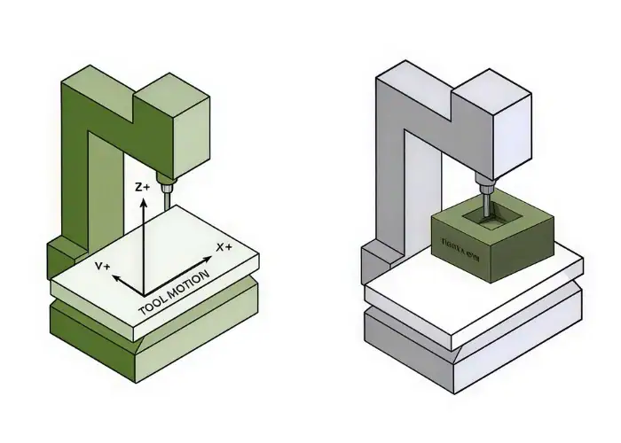
The X, Y, and Z axes control the cutter’s horizontal position, front-to-back position, and vertical cutting depth. The X-axis generally moves left to right, the Y-axis moves forward and backward, and the Z-axis moves the cutter toward or away from the workpiece.
These three movements define the cutter’s position within the machine envelope. By coordinating the axes, the machine can follow straight lines, circular paths, pockets, profiles, and three-dimensional surfaces while maintaining programmed feeds and depths.
A CNC 3 axis system controls position but does not automatically change the cutter’s angle of approach. The cutter normally remains vertical, which makes top-down features efficient but limits access to hidden, angled, or wraparound geometry.
How Does 3 Axis CNC Differ From Manual Machining?
3 axis CNC milling differs from manual machining because computer instructions control tool movement, spindle speed, feed rate, depth, and operation sequence. Manual milling depends more heavily on an operator moving the machine axes and making adjustments during production.
CNC control improves repeatability because the same verified program can manufacture multiple components using consistent coordinates and cutting parameters. The operator still controls setup, tooling, offsets, inspection, and process stability, but does not manually guide every cutting movement.
Manual milling remains useful for repairs, adjustments, simple one-off work, and shop-floor modifications. CNC machining is generally more suitable when a part requires repeatable dimensions, documented programs, complex toolpaths, or multiple production quantities.
How Does 3 Axis CNC Milling Work?
3 axis CNC milling works by converting a CAD model and engineering drawing into programmed toolpaths that guide the cutter through a controlled sequence of material-removal operations. The complete process includes design review, CAM programming, workholding, machining, inspection, and any required secondary finishing.
CAD Design and CAM Programming
CAD design and CAM programming define what the part should look like and how the machine will cut it. The CAD model contains the geometry, while the drawing defines material, datums, tolerances, threads, surface finish, and other manufacturing requirements.
The CAM programmer selects cutting tools and creates roughing, semi-finishing, drilling, tapping, contouring, and finishing operations. Toolpaths must account for material behavior, cutter diameter, cutting depth, tool reach, chip evacuation, and workholding clearance.
The completed CAM program is converted into machine-readable CNC code through a suitable post-processor. Before cutting begins, the programmer or operator should verify tool numbers, offsets, spindle commands, work coordinates, and safe approach movements.
Workpiece Setup and Tool Selection
Workpiece setup and tool selection establish the rigidity, accessibility, and cutting conditions required to machine the component. The raw stock is normally held in a vise, soft jaws, fixture plate, vacuum fixture, clamp system, or custom nest.
The fixture must prevent movement without distorting thin walls or marking functional surfaces. It must also provide enough access for the toolholder, spindle, probe, and cutting tool throughout the programmed operations.
Tool selection depends on the material and feature geometry. Face mills, flat end mills, ball-end mills, drills, thread mills, taps, chamfer tools, and boring tools may all be used within one part program.
Cutting Tool Movement and Material Removal
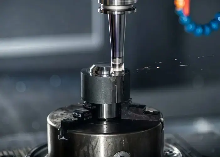
Material removal occurs when the rotating cutter follows programmed X, Y, and Z movements while removing controlled amounts of stock. Roughing operations remove most of the material, while finishing operations establish final dimensions and surface quality.
Tool engagement should remain stable to control cutting force, heat, vibration, and tool wear. Excessive depth, poor chip evacuation, long tool overhang, or abrupt engagement can produce chatter, deflection, dimensional error, and damaged cutting edges.
The machining sequence should also control part movement. Large pockets, thin walls, and uneven stock removal can release internal material stress, so roughing and finishing may need to be separated by rest periods, part flipping, or intermediate inspection.
Inspection and Finishing
Inspection and finishing confirm that the machined component meets its dimensional, geometric, and surface requirements. Measurement may be performed during setup, between machining stages, or after the component has been removed from the fixture.
Common inspection equipment includes calipers, micrometers, height gauges, bore gauges, thread gauges, surface roughness testers, optical systems, and coordinate measuring machines. The selected method should reproduce the drawing’s datum system and measure the functional relationships that matter.
After inspection, the part may require deburring, polishing, bead blasting, anodizing, plating, powder coating, heat treatment, or another secondary process. Coating thickness and finishing allowances should be considered before final machining.
What Machines Are Used for 3 Axis CNC Milling?
The machines used for 3 axis CNC milling include vertical machining centers, horizontal machining centers, gantry mills, and CNC routers. Each machine uses three controlled linear axes, but its rigidity, spindle arrangement, working envelope, and suitable materials can differ significantly.
Vertical 3 Axis CNC Milling Machines
Vertical 3 axis CNC milling machines position the spindle vertically above the workpiece. They are widely used for plates, brackets, housings, fixtures, molds, prototypes, and other parts that contain accessible top-down features.
Vertical machines provide good visibility during setup and work effectively with standard vises, soft jaws, fixture plates, and probes. Their common configuration also makes programming, maintenance, tooling, and operator training relatively accessible.
They are generally the first choice for small and medium-sized prismatic parts. The practical part size depends on axis travel, table capacity, tool length, fixture height, and spindle clearance.
Horizontal 3 Axis CNC Milling Machines
Horizontal 3 axis CNC milling machines position the spindle parallel to the machine table. They are useful for heavier cutting, improved chip evacuation, and parts whose main features are better approached from the side.
Horizontal configurations can offer high structural rigidity and may support pallet systems for repeat production. However, workholding and setup planning can be more complex than on a typical vertical machine.
A standard horizontal machine still has limited approach directions unless it includes additional rotary capability. The machine orientation alone does not convert a three-axis system into a four-axis or five-axis process.
Gantry Milling Machines
Gantry milling machines use a bridge-style structure to machine large plates, molds, tooling components, structural parts, and machine bases. Their main advantage is a large working area supported by a rigid frame.
These machines can process components that are too long, wide, or heavy for a conventional machining center. Typical applications include large mold plates, equipment bases, aerospace structures, and industrial tooling.
Accuracy across a large travel range depends on machine construction, thermal stability, foundation condition, calibration, and workpiece support. A large machine envelope does not remove the need for stable fixturing and inspection.
Industrial CNC Mills vs. CNC Routers
Industrial CNC mills are more suitable for rigid, high-precision metal cutting, while CNC routers are generally optimized for large sheets and softer materials. Routers commonly process wood, foam, plastics, composites, and thinner non-ferrous materials.
A machining center normally has greater structural mass, stronger spindle torque, more controlled axis motion, and better resistance to cutting force. These characteristics make it more suitable for steels, titanium, deep pockets, tight GD&T, and demanding surface requirements.
A router may still be the economical choice for large panels, plastic sheets, composite plates, and low-force cutting. Machine selection should be based on material, tolerance, geometry, cutting load, and surface expectations rather than axis count alone.
What Can 3 Axis CNC Milling Do?
3 axis CNC milling can produce flat faces, profiles, holes, threads, pockets, slots, steps, cavities, and accessible three-dimensional contours. Its strongest capability is efficient machining of features that can be reached from one fixed cutter orientation.
Face Milling and Contouring
Face milling and contouring create flat surfaces, external profiles, shoulders, steps, and controlled part boundaries. These operations are common on mounting plates, machine bases, brackets, enclosures, and tooling components.
Face milling can establish a stable datum surface before other features are machined. Contouring then defines external geometry using an end mill that follows the programmed boundary.
Accuracy depends on machine alignment, tool runout, cutter condition, workholding, and the number of finishing passes. Large flat surfaces may require planned tool overlap and controlled thermal conditions to maintain flatness.
Drilling, Boring, and Tapping
Drilling, boring, and tapping produce holes, precision bores, threads, counterbores, countersinks, and fastening features. A three-axis mill can locate these features accurately when their axes are parallel to the machine’s Z direction.
Drilling creates the initial hole, while boring or circular interpolation can improve size, roundness, and position. Tapping or thread milling then produces the required internal thread.
Angled or side-facing holes usually require a new setup, an angle fixture, or a multi-axis machine. The hole may be simple, but its direction relative to the primary datum determines the manufacturing complexity.
Slots, Pockets, Steps, and Cavities
Slots, pockets, steps, and open cavities are among the most suitable features for 3 axis CNC milling. They can be rough machined efficiently using standard end mills and then finished with controlled wall and floor passes.
Open geometry provides direct access for the cutter and allows better chip removal. Closed or deep pockets become more difficult because the tool must extend farther from the holder and evacuate chips through a limited opening.
Internal corner radii are determined by cutter size. A rotating end mill cannot produce a perfectly sharp internal vertical corner, so designs should use practical fillets or relief features.
Simple 2.5D and 3D Contours
3 axis CNC milling can produce both 2.5D features and accessible 3D contoured surfaces. Ball-end mills and coordinated axis movement can machine molds, curved pockets, sculpted surfaces, and smooth transitions from a fixed direction.
The process can create complex-looking surfaces as long as the cutter has direct line-of-sight access. Geometric complexity alone does not always require five-axis machining.
The limitation appears when the same contoured surface wraps around multiple faces or contains undercuts. The cutter may follow the surface accurately from above but cannot tilt to reach behind an obstruction.
What Materials Can Be Machined With 3 Axis CNC Milling?
3 axis CNC milling can machine most common metals, engineering plastics, composites, and specialty machinable materials when the machine, tooling, workholding, coolant, and dust controls are suitable. Axis count defines movement, while actual material capability depends on the complete machining system.
| Material Group | Typical Materials | Main Machining Considerations |
| Aluminum | 6061, 6082, 7075, 2024 | Burr control, thin-wall distortion, high cutting speeds |
| Steel | 1018, 4140, 4340, tool steel | Cutting force, heat, tool wear, heat-treatment condition |
| Stainless Steel | 303, 304, 316, 17-4PH | Work hardening, heat concentration, stable engagement |
| Copper and Brass | C101, C110, C360 | Adhesion, burr formation, chip control, surface marking |
| Engineering Plastics | POM, PEEK, nylon, PC, PTFE | Heat, clamping deformation, moisture, dimensional recovery |
| Composites | FR4, G10, CFRP, GFRP | Abrasion, dust extraction, delamination, edge quality |
Aluminum is commonly selected because it machines efficiently and supports lightweight structural, electronic, automotive, and prototype components. Steel and stainless steel require more rigid cutting conditions but are suitable for tooling, industrial, medical, and load-bearing parts.
Engineering plastics require sharp tools and controlled heat because excessive temperature or clamping force can change the final dimensions. Materials such as nylon may also require moisture and measurement conditions to be considered.
Material grade should be chosen according to strength, corrosion resistance, temperature, wear, electrical performance, finishing, and cost. Selecting a material only because it machines easily can produce a component that does not meet its service requirements.
What Parts Can Be Made With 3 Axis CNC Milling?
3 axis CNC milling can manufacture simple-to-moderate prismatic parts whose critical features are accessible from one or several straightforward setups. Common examples include housings, plates, brackets, tooling, fixtures, molds, manifolds, covers, and prototypes.
| Part Type | Typical Machined Features | Why 3 Axis Works |
| Housings and Enclosures | Pockets, connector openings, mounting holes | Most features are accessible from the top and bottom |
| Brackets and Plates | Profiles, slots, holes, counterbores | Flat stock and simple datums support efficient fixturing |
| Jigs and Fixtures | Locating holes, pockets, datum surfaces | Repeatability and practical tolerances are important |
| Mold Bases and Inserts | Cavities, cooling holes, mounting features | Open cavities can be reached with standard tools |
| Manifolds | Ports, bores, sealing faces | Suitable when holes follow simple setup directions |
| Prototypes | Mixed standard features | Fast programming supports design iteration |
| Low-Volume Parts | Repeatable pockets and profiles | Setup cost can be distributed without dedicated tooling |
The process is particularly effective for flat or box-shaped components. A housing with one deep pocket, several vertical holes, external profiles, and a machined bottom face may require only two primary setups.
Three-axis equipment can also support more complex parts through custom fixtures and repeated repositioning. However, each extra setup should be justified because it adds handling, probing, alignment, inspection, and potential error.
What Are the Main Benefits of 3 Axis CNC Milling?
The main benefits of 3 axis CNC milling are process simplicity, broad availability, lower programming effort, reliable repeatability, and economical production of accessible geometry. These advantages make it valuable for prototypes, replacement parts, tooling, and production components.
Proven Reliability and Process Simplicity
3 axis CNC milling is reliable because the machine controls only three linear movements and uses established programming, tooling, and setup methods. Fewer motion systems generally make the process easier to understand, operate, maintain, and troubleshoot.
The straightforward structure also supports predictable production. Operators can verify axis motion, tool offsets, work coordinates, and fixtures without managing simultaneous rotary movement.
Reliability still depends on machine condition and process control. Worn guides, spindle runout, poor toolholding, incorrect offsets, or unstable fixturing can affect quality on any CNC machine.
Lower Machine and Production Costs
3 axis CNC milling usually has lower operating and programming costs than multi-axis machining for simple parts. Machines, fixtures, software requirements, training, maintenance, and hourly rates are generally less demanding.
Standard vises, fixture plates, parallels, clamps, and common cutting tools can support a wide range of jobs. This reduces the need for specialized rotary workholding or advanced collision simulation.
The cost advantage can disappear when a complex part requires many manual setups. Buyers should compare total programming, handling, inspection, fixture, and machine time rather than assuming three axes are always cheaper.
Faster Programming and Setup
3 axis CNC milling supports faster programming because the CAM system mainly controls linear cutter position rather than both position and changing tool orientation. Toolpath verification and machine prove-out are therefore usually more straightforward.
Physical setup is also efficient for parts that fit standard vises or fixture plates. A clear primary datum and accessible geometry can reduce probing, alignment, and custom workholding.
This advantage is valuable for rapid prototypes and design revisions. When the geometry changes, the program and fixture can often be updated without rebuilding a complex multi-axis strategy.
Good Accuracy and Repeatability
3 axis CNC milling provides good accuracy and repeatability when the machine, fixture, tooling, material, and inspection process are properly controlled. Features machined in one setup maintain a consistent relationship to the same coordinate system.
Repeatability supports production quantities because a verified program can be reused with controlled tool offsets and workholding. In-process probing and tool measurement can further reduce setup variation.
The machine does not guarantee a particular tolerance by axis count alone. Required accuracy must be evaluated according to part size, material stability, feature relationships, wall thickness, surface finish, and measurement capability.
Wide Availability and Manufacturing Support
3 axis CNC milling is widely available because it is a standard process in general machine shops, prototype suppliers, toolrooms, and production facilities. Skilled operators, programmers, cutters, holders, replacement parts, and training resources are broadly accessible.
This availability can improve scheduling flexibility and supplier options. It also makes it easier to transfer mature programs between compatible equipment when process controls are documented.
Supplier availability should not replace technical qualification. Buyers still need to assess machine condition, material experience, inspection resources, quality systems, and the supplier’s understanding of the drawing.
What Are the Limitations of 3 Axis CNC Milling?
The main limitations of 3 axis CNC milling are fixed tool orientation, restricted access to hidden features, multiple setups for multi-sided parts, and reduced efficiency on complex geometry. These limits affect cost, accuracy, lead time, and manufacturability.
Limited Access to Side and Angled Features
3 axis CNC milling has limited access to side and angled features because the tool normally approaches the workpiece from one fixed direction. A side hole or angled surface may be impossible to reach in the primary setup.
The component can be repositioned in a vise, angle plate, custom fixture, or soft jaws to expose the feature. This makes many parts technically machinable, but the added operation increases setup effort.
When several angled features point in unrelated directions, four-axis or five-axis machining may provide a more stable and economical process.
Multiple Setups for Multi-Sided Parts
Multi-sided parts require multiple setups when their features cannot all be reached from one orientation. Each setup may involve part removal, cleaning, repositioning, clamping, probing, and offset verification.
Critical features machined in different setups depend on the accuracy of the fixture and datum transfer. Small location changes can accumulate and affect position, perpendicularity, concentricity, or alignment.
Well-designed soft jaws, locating pins, machined datums, and probing routines can reduce this risk. However, they do not remove the handling time associated with repeated setups.
Restrictions on Undercuts and Hidden Geometry
Undercuts and hidden internal geometry are difficult or impossible to machine when surrounding material blocks the cutter’s approach. A tool cannot pass through a solid wall simply because the machine can coordinate three axes.
Special undercut tools, lollipop cutters, T-slot cutters, or custom fixturing may solve selected features. These tools still require a physical access path and enough clearance for the holder.
Fully enclosed channels, reverse-facing surfaces, and deep hidden features may require EDM, part splitting, additive manufacturing, or a design change rather than conventional three-axis milling.
Deep Cavities and Long Tool Overhang
Deep cavities are difficult because the cutter must extend farther from the toolholder to reach the bottom. Greater overhang reduces rigidity and increases the risk of vibration, deflection, poor finish, and tool breakage.
Narrow cavity openings also restrict chip evacuation and coolant access. Recut chips can damage the surface and increase heat around the cutting edge.
Increasing the cavity width, reducing depth, using larger internal radii, or dividing the geometry into stepped regions can improve machinability. A five-axis approach may also allow a shorter tool, but only when the surrounding geometry permits tilting.
Reduced Efficiency for Complex Geometry
3 axis CNC milling becomes less efficient when a part requires many setups, angle fixtures, small tools, or difficult datum transfers. Lower hourly machine cost does not guarantee lower total part cost.
Complex parts may spend more time being repositioned and inspected than being cut. Each transition also increases work-in-process and the chance of rework.
The best process is therefore the simplest machine configuration that completes the full manufacturing route reliably. For some parts that is three axes, for others, additional axes reduce total effort.
Design Guidelines for 3 Axis CNC Milling
Good 3 axis CNC milling design keeps important features accessible, uses practical radii and cavity depths, provides stable wall thickness, and creates clear surfaces for workholding. These choices reduce tool reach, setups, vibration, inspection difficulty, and production cost.
Keep Features Accessible From One Direction
Features should be accessible from one primary direction whenever possible. Top-facing holes, pockets, slots, and profiles allow the manufacturer to complete more work without changing fixtures.
Related functional features should also be grouped around common datums. This allows holes, bores, sealing surfaces, and mounting interfaces to be machined and inspected within the same coordinate system.
When multiple directions are necessary, designers should minimize their number and avoid unrelated compound angles. A small orientation change may create an entire additional setup.
Use Practical Internal Corner Radii
Internal corners should use practical radii because cylindrical milling cutters cannot produce perfectly sharp internal vertical corners. The radius should allow a stable tool to machine the feature without full cutter engagement.
Very small radii require small-diameter tools. Small tools are less rigid, remove less material per pass, and may require longer cycle times.
Increasing a nonfunctional radius can improve tool life, surface finish, and production speed. Relief cuts may be used when a square mating component must fit into an internal corner.
Avoid Deep and Narrow Cavities
Deep and narrow cavities should be avoided because they require long tools, limited cutting depths, and difficult chip evacuation. These conditions increase chatter, heat, deflection, and tool wear.
A cavity can often be improved by increasing the opening width, reducing depth, adding larger corner radii, or creating stepped levels. These changes allow stronger tools and more stable cutting engagement.
Depth should be based on function rather than appearance. Removing additional material from an invisible region may increase machining cost without improving the part.
Maintain Suitable Wall Thickness
Wall thickness should be sufficient to resist cutting force, clamping pressure, and material stress. Thin or tall walls may bend during machining and move after the fixture is released.
The practical thickness depends on material, wall height, length, tolerance, and finish. A plastic wall may react differently from aluminum, stainless steel, or titanium at the same nominal thickness.
Temporary support, balanced roughing, light finishing passes, and controlled clamping can reduce distortion. Design changes are usually more reliable than trying to compensate for an extremely flexible wall through machining alone.
Design for Stable Workholding
Stable workholding requires accessible clamping surfaces, clear locating datums, and enough stock to support the part during roughing and finishing. The fixture should hold the component without blocking critical features.
Sacrificial tabs, removable bases, stock extensions, soft-jaw profiles, or fixture holes can support difficult components. These temporary features can be removed during the final operation.
Workholding should be discussed before the design is frozen. A part that has no rigid gripping area may require expensive custom fixtures or unnecessary additional setups.
Where Is 3 Axis CNC Milling Used?
3 axis CNC milling is used across automotive, industrial equipment, medical, aerospace, automation, electronics, robotics, consumer products, tooling, and energy applications. It is most valuable for plates, housings, brackets, bases, fixtures, and other accessible prismatic parts.
| Industry | Common 3 Axis Milled Parts | Main Manufacturing Value |
| Automotive | Brackets, covers, flanges, tooling plates | Repeatable dimensions and economical production |
| Industrial Equipment | Bases, wear plates, manifolds, fixture parts | Rigidity, standard geometry, material flexibility |
| Medical | Device housings, trays, handles, brackets | Controlled dimensions and clean surface finishing |
| Aerospace | Fittings, panels, brackets, tooling | Accurate accessible features and lightweight materials |
| Automation | Sensor mounts, nests, gripper plates | Fast customization and repeatable assembly interfaces |
| Electronics | Aluminum housings, heat sinks, test fixtures | Precise pockets, openings, and thermal surfaces |
| Robotics | Motor mounts, adapter plates, fixture components | Accurate hole patterns and structural alignment |
| Consumer Products | Enclosures, covers, prototypes | Fast iteration and cosmetic finishing options |
| Tool and Die | Mold bases, inserts, jigs, fixtures | Stable datums and repeatable machining |
| Energy and Oil & Gas | Valve plates, supports, sealing components | Strong materials and controlled functional surfaces |
Industry alone does not determine the axis requirement. An aerospace bracket with open pockets may suit a three-axis machine, while a consumer product containing compound curves and hidden features may require five-axis machining.
The decision should begin with geometry, access, tolerance, setup count, material, quantity, and inspection. Industry labels are secondary to the actual manufacturing requirements.
3 Axis vs. 4 Axis vs. 5 Axis CNC Milling
The difference between 3 axis, 4 axis, and 5 axis CNC milling is the number of controlled directions used to position the cutter and orient the workpiece. Additional axes improve access and reduce repositioning, but increase equipment, programming, simulation, and process requirements.
| Process | Controlled Movement | Best Fit | Main Limitation |
| 3 Axis Milling | X, Y, and Z | Plates, pockets, brackets, housings, open contours | Fixed cutter orientation |
| 4 Axis Milling | X, Y, Z plus one rotary axis | Cylindrical parts, radial holes, indexed side features | Rotation follows one primary axis |
| 5 Axis Milling | X, Y, Z plus two rotary axes | Multi-face, angled, deep, and freeform geometry | Higher programming and machine cost |
A practical 4 axis vs 3 axis CNC comparison begins with rotation. Four-axis machining can automatically index or continuously rotate a part around one direction, making it useful for radial features, cylindrical components, and several sides arranged around a common centerline.
Five-axis machining adds another rotary movement, allowing the cutter or workpiece to tilt in two directions. It becomes valuable for compound angles, multiple critical faces, deep access, impellers, complex molds, and freeform surfaces.
For readers searching for CNC axis explained, the correct choice is not automatically the machine with the most axes. The correct choice is the least complex process that can meet geometry, tolerance, lead-time, and production requirements without excessive setups.
What Affects 3 Axis CNC Milling Cost and Lead Time?
3 axis CNC milling cost and lead time are affected by geometry, material, setup count, tooling, tolerances, surface finish, inspection, secondary processing, production quantity, and delivery requirements. Machine time is only one part of the total manufacturing cost.

Part Geometry and Number of Setups
Part geometry affects cost because every new orientation may require additional fixtures, probing, alignment, cutting operations, and inspection. A simple-looking part can become expensive when features are spread across several sides.
Accessible pockets and hole patterns are usually economical. Hidden features, deep cavities, angled holes, thin walls, and multiple precision faces increase preparation and process risk.
Reducing the number of setups is often more valuable than shortening one toolpath. A design review should examine the complete manufacturing route rather than only the programmed cutting cycle.
Material and Tooling Requirements
Material affects cost through stock price, cutting speed, cutter wear, heat control, coolant requirements, and machining risk. Aluminum generally supports faster removal than hardened steel, titanium, or nickel alloys.
Tooling cost increases when the part requires long-reach cutters, small end mills, special threads, custom form tools, or frequent tool replacement.
Stock form also matters. Oversized material increases roughing time and waste, while near-net stock may cost more to purchase or require larger minimum quantities.
Tolerances and Surface Finish
Tight tolerances increase cost because they require stable tooling, controlled temperature, additional finishing passes, probing, measurement, and documented inspection.
Fine surface finishes require smaller stepovers, sharper tools, slower finishing operations, or manual polishing. Cosmetic surfaces may also require controlled toolpath direction and careful handling.
Functional requirements should be applied only where needed. General tolerances and standard machined finishes are normally sufficient for noncritical regions.
Production Volume and Secondary Operations
Production quantity affects how setup, programming, fixture, and inspection costs are distributed. Prototypes carry more fixed engineering cost per part, while repeat quantities can benefit from proven programs and reusable workholding.
Higher quantities may justify dedicated fixtures, multi-part setups, automated probing, and tool-life management. These investments can reduce cycle variation and handling.
Anodizing, plating, heat treatment, polishing, passivation, and special inspection add separate lead-time stages. Drawings should define these processes early so manufacturing and finishing allowances can be planned together.
When Should You Choose 3 Axis CNC Milling?
You should choose 3 axis CNC milling when the part contains accessible geometry, moderate complexity, practical tolerances, and a production route that does not require excessive repositioning. It is especially suitable when cost control and fast programming are important.
Parts With Simple or Top-Down Geometry
Parts with flat surfaces, vertical walls, open pockets, slots, top-facing holes, and straightforward contours are strong candidates for three-axis milling.
These features allow standard tools and workholding to be used without complicated approach angles. The result is predictable programming, stable cutting, and efficient inspection.
A part does not need to be visually simple. It can contain detailed pocket patterns and contoured surfaces, provided the cutter can reach them from a fixed direction.
Rapid Prototypes and Small-Batch Production
Rapid prototypes and small batches benefit from three-axis milling because programming, setup, and design revisions can be completed quickly.
The process can manufacture functional parts directly from production-grade metal or plastic without dedicated molds. This supports fit, assembly, mechanical, thermal, and user testing.
Early designs should avoid unnecessary tolerances and cosmetic controls. Prototype cost should focus on validating the features that affect function.
Cost-Sensitive General Engineering Parts
Cost-sensitive general engineering parts are suitable when they can be produced with standard tools, fixtures, materials, and inspection methods.
Brackets, plates, covers, machine components, replacement parts, and fixture elements often fall into this category.
Three-axis machining is not automatically economical when the design contains many side operations. The cost advantage depends on the complete setup route.
When Should You Use More Axes?
You should use more axes when a part contains compound angles, multi-face critical relationships, extensive side features, difficult undercuts, wrapped geometry, or deep areas that require excessive tool overhang.
Four-axis machining can reduce handling when features are distributed around a cylindrical or indexed direction. Five-axis machining can reduce setups when features require two independent angular directions.
Additional axes should provide measurable value through access, shorter tools, fewer fixtures, improved alignment, or shorter overall lead time.
FAQs
How Accurate Is 3 Axis CNC Milling?
3 axis CNC milling can produce precise and repeatable parts, but achievable accuracy depends on machine condition, material, part size, feature geometry, fixture rigidity, tool runout, temperature, and inspection. Features completed in one setup generally maintain better positional relationships than features transferred across multiple setups.
Can 3 Axis CNC Milling Machine Complex Parts?
3 axis CNC milling can machine complex pockets, contours, molds, and three-dimensional surfaces when the cutter has direct access from a fixed orientation. It becomes less suitable when features are hidden, undercut, distributed across many faces, or positioned at unrelated compound angles.
What Are The 3 Axis CNC Machined Parts?
3 axis CNC machined parts are usually components with features accessible from the X, Y, and Z directions. Common examples include aluminum housings, brackets, mounting plates, covers, heat sinks, mold inserts, jigs, fixtures, manifolds, and prototype parts. These parts often include flat surfaces, holes, slots, pockets, steps, threads, and 2.5D contours. 3-axis machining is ideal when most features can be completed from 1–2 setups with standard tools and stable workholding.
What Is The Difference Between 3 Axis And 5-Axis Milling?
The difference between 3 axis and 5-axis milling is tool access and motion control. 3-axis milling uses X, Y, and Z linear movement, so the cutter mainly approaches the part from one fixed direction. 5-axis milling adds 2 rotary axes, allowing the tool or workpiece to tilt for multi-angle machining. 3-axis is cost-effective for simple parts, while 5-axis can reduce 3–5 setups into 1 setup for complex surfaces, deep cavities, angled holes, and precision multi-face parts.
What Is The Difference Between 3 Axis And 4 Axis Milling?
The difference between 3 axis and 4 axis milling is that 4-axis milling adds 1 rotary axis to the standard X, Y, and Z movements. 3-axis milling is best for flat faces, vertical holes, pockets, slots, and open contours. 4-axis milling can rotate the workpiece, making it better for cylindrical parts, radial holes, curved profiles, and multi-side features. Compared with 3-axis machining, 4-axis machining can reduce manual repositioning, improve consistency, and shorten setup time for parts with features around one direction.
Conclusion
3 axis CNC milling provides a reliable and economical way to manufacture plates, brackets, housings, fixtures, prototypes, and other parts with accessible geometry. Its main strengths are straightforward programming, standard workholding, broad material compatibility, repeatable accuracy, and efficient production. Its limitations appear when a design contains hidden features, compound angles, deep cavities, or critical surfaces spread across several orientations.
At TiRapid, we provide precision CNC machining and manufacturing services for custom metal and plastic parts. Our team supports prototypes and low-volume production with material review, DFM feedback, 3-axis and multi-axis milling, dimensional inspection, surface finishing, and process selection based on your part geometry, tolerance, budget, quantity, and lead-time requirements.