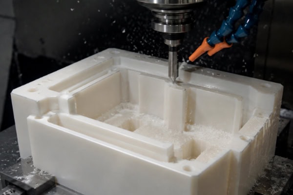
Deep-cavity machining is one of the more demanding operations in plastic CNC machining. Unlike shallow slots or surface-level work, deep cavities involve substantial tool overhang and confined chip-evacuation space. If chips are not cleared in time, they are repeatedly recut by the tool, leading to surface scoring, elevated cutting temperatures, and, in severe cases, tool breakage or scrapped workpieces. Because plastics generally have poor thermal conductivity, heat does not dissipate readily through the workpiece itself, making the temperature rise caused by poor chip evacuation a more pronounced concern than in metal machining.
Root Causes of Chip-Evacuation Difficulty in Deep Cavities
Structural Limitations Due to Tool Overhang
In deep-cavity machining, the tool holder diameter is typically smaller than the cavity width, requiring the tool to extend a considerable distance to reach the bottom. The greater the overhang, the lower the tool rigidity, and the more pronounced vibration and runout become during cutting. At the same time, long-overhang tools offer limited flute space; near the cavity floor in particular, the upward escape path for chips is narrow and lengthy. Because plastic chips tend to be relatively bulky and soft, they are especially prone to packing in these confined spaces.
The Nature of Plastic Chips
Different plastics produce distinctly different chip forms, and the difficulty of chip evacuation varies accordingly. Nylon-type materials tend to generate long, stringy chips that readily wrap around the tool and cause blockages. PC and acrylic produce chips that are more brittle but also generate fine dust, which can mix with coolant to form a pasty buildup at the bottom of the cavity. POM chips are comparatively well-behaved in form, but they too will clog if the evacuation path is insufficient. Different chip types call for different evacuation approaches.
How Tool Selection Affects Chip Evacuation
Number of Flutes
In deep-cavity machining, single-flute or two-flute end mills generally deliver better chip evacuation than multi-flute tools. A single-flute tool has the largest flute space, giving chips ample room to travel upward through the helical channel. Two-flute tools offer a balance between cutting efficiency and evacuation capacity. Tools with three or more flutes may theoretically allow higher feed rates, but in deep-cavity conditions the reduced flute space makes chip packing more likely.
The following guidelines can be used when selecting flute count:
- When the cavity depth-to-width ratio exceeds 3:1, a single-flute end mill is the preferred choice
- For depth ratios between 2:1 and 3:1, a two-flute end mill is generally suitable
- For shallow cavities with a depth ratio below 2:1, multi-flute tools rarely present chip-evacuation issues
Tool Geometry
Beyond flute count, the helix angle, flute profile, and cutting-edge design also influence chip evacuation. A larger helix angle (in the range of 35 to 45 degrees) helps propel chips upward along the tool, offering an advantage over low-helix tools in deep-cavity work. However, an excessively large helix angle also increases the axial component of cutting force, which may introduce additional deflection in long-overhang tools with limited rigidity; a balanced choice should be made based on the specific depth and tool diameter. The surface finish of the flute also warrants attention—the smoother the flute wall, the less likely chips are to adhere. Some purpose-built tools for plastic machining feature mirror-polished flutes, which are particularly effective in challenging applications such as deep-cavity nylon machining, where material sticking is a known problem.
Optimizing the Cutting Approach
Layered Machining to Control Chip Volume
In deep-cavity machining, attempting to reach full depth in a single pass is not recommended. Taking the cavity in successive layers keeps the chip volume per pass manageable and reduces the burden on evacuation. The depth of cut per layer should be determined based on material hardness, tool diameter, and cavity depth. For acrylic and PC, the depth per pass is typically limited to 10 to 20 percent of tool diameter. POM can generally handle 25 to 30 percent. Nylon calls for a more conservative approach to prevent stringy chips from clogging the flute.
Helical or Ramped Entry
Plunging straight down carries significant risk in deep-cavity work: cutting pressure concentrates at the tool tip, and chips can only escape upward through the narrow gap along the tool sidewall. Entering on a helical or ramped path allows the tool to generate lateral cutting action as it descends, making it easier for chips to be carried out through the helical motion. A helix angle of 3 to 5 degrees is typical, with a pitch of 50 to 80 percent of tool diameter.
Adding Retract Moves to Clear Chips
Building periodic retract movements into the deep-cavity program gives the tool a brief window to leave the cutting zone, allowing spindle rotation to fling off any chips adhering to the tool while also giving compressed air or coolant a chance to clear the cavity floor. Retract frequency should be based on how quickly chips accumulate: the deeper the cavity and the more prone the material is to stringy chip formation, the more frequent the retracts should be. Some CAM packages support automatically inserting retract moves based on depth or toolpath distance.
Auxiliary Chip-Evacuation Methods
Effective Use of Compressed Air
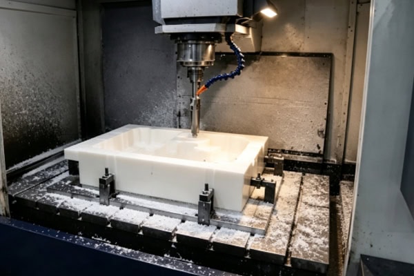
Compressed air is the most commonly used auxiliary method for chip evacuation in deep-cavity plastic machining. The air stream should be aimed at the cutting zone, not simply directed at the workpiece surface. For deep cavities, extended nozzles or articulating air lines can be used to deliver the airflow directly to the tool tip, blowing chips out from the source. Air pressure is generally set between 0.4 and 0.6 MPa. Excessive pressure may scatter lightweight chips uncontrollably, while insufficient pressure will lack the force needed to clear them. It is worth noting that compressed air provides a secondary benefit in deep-cavity machining: cooling. As the air flows between the tool and the cavity wall, it carries away a portion of the heat. While less efficient than liquid cooling, this is usually sufficient for most plastic materials and avoids the complications of liquid residue.
Combining with Minimum-Quantity Lubrication
For plastics that are particularly prone to sticking to the tool—such as ABS and certain grades of nylon—adding a small amount of oil mist to the compressed air stream can help. A thin film of lubricant on the tool surface reduces chip adhesion and helps chips slide through the flute. However, the oil mist volume must be carefully controlled: too much lubricant can cause chips and oil to mix into a sludge-like buildup at the cavity floor, worsening the evacuation problem. The flow rate is generally adjusted until the chips show a slight surface dampness without clumping together.
Toolpath Planning and Program Optimization
Choosing the Cutting Direction
The cutting direction in deep-cavity machining affects the natural escape path of the chips. Where possible, plan the cutting sequence from the cavity center outward, or from deep to shallow, so that chips always have a tendency to move toward open space. Avoid toolpaths that converge from the perimeter toward the center, as these continuously drive chips deeper into the cavity.
Adjusting the Milling Mode
In deep-cavity sidewall machining, climb milling generally produces chip forms that are more favorable for evacuation—the chips are more intact and their direction is more predictable—whereas conventional milling tends to produce finer, more fragmented chips that accumulate more readily at the cavity bottom. Climb milling does, however, place higher demands on tool rigidity and machine accuracy. Where tool overhang is large and rigidity is a concern, a mix of climb and conventional milling can be used to balance evacuation needs against machining stability.
Separating Roughing and Finishing Operations
Roughing and finishing passes for deep cavities should be planned separately. The roughing stage focuses on efficient material removal, using larger stepovers and deeper cuts, supported by frequent retracts for chip clearing. The finishing stage prioritizes surface quality and dimensional accuracy, with narrower stepovers and reduced depths of cut; at this point the chip-evacuation load is already far lower than during roughing. Allow sufficient clearing time between the two stages to ensure no residual chips remain at the cavity bottom before finishing begins.
Frequently Asked Questions
Can chip-evacuation problems in deep-cavity machining be solved simply by changing the tool?
Changing the tool is one approach. Selecting a suitable tool—particularly in terms of flute count and flute design—can make a noticeable difference to chip evacuation. However, if the cutting approach, toolpath design, and auxiliary evacuation methods are not adjusted accordingly, changing the tool alone will rarely resolve deep-cavity chip problems entirely. The most common mistake is switching to a single-flute tool without altering the entry method or cutting parameters, which yields only limited improvement.
Why does the same program produce good chip evacuation on some plastic sheets but clogging on others within the same batch?
If cutting parameters and tooling are identical but evacuation performance is inconsistent, several factors should be checked: batch-to-batch material variation (different batches of the same grade of plastic sheet may differ in hardness, internal stress, and surface condition); the degree of tool wear (a tool that has already begun to wear is more likely to produce altered chip forms and clogging than a fresh tool); stability of the compressed air supply; and changes in workshop temperature and humidity (nylon-type materials are particularly sensitive to moisture levels).
In conclusion
There is no one-size-fits-all solution to chip-evacuation problems in deep-cavity plastic machining. The approach must be tailored to the specific plastic material, the cavity geometry, and the actual machining conditions. Getting the flute count right is the foundation; the cutting strategy and toolpath design determine the upper limit of evacuation efficiency; and auxiliary methods such as compressed air ensure stability throughout the process. For deep-cavity parts going into production, it is worth investing time at the trial stage to fully validate the chip-evacuation strategy. Once chip control is lost during deep-cavity machining, surface scoring and dimensional deviations are often irreversible, and the cost of rework and material scrap far outweighs the effort spent on process development.