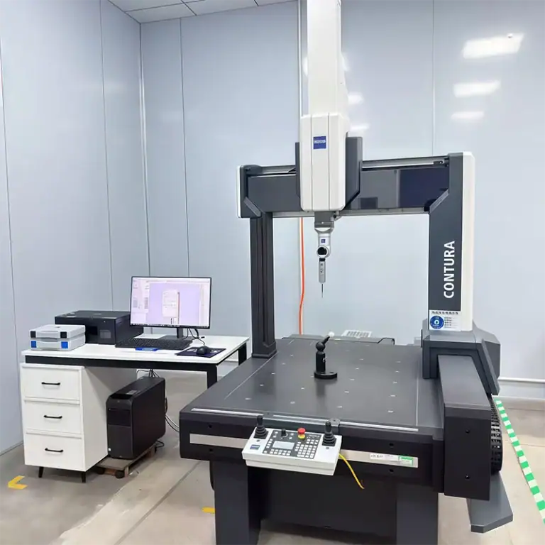
Once a part has been machined, the real headache is often not whether it can be produced, but whether it looks fine yet fails during assembly. This is especially common with precision components. Some dimensional deviations are impossible to see with the naked eye, but they can cause problems such as poor fit, excessive clearance, or even installation failure. Inspection after precision machining is used to identify these hidden issues before the parts move into assembly. Dimensions, geometric tolerances, surface roughness, and appearance all require suitable inspection methods. Different components call for different measuring tools, and relying on a single caliper from start to finish is rarely enough.
What Should Be Checked First When a Precision Machined Part Arrives?
After a precision component reaches the inspection stage, it is not a good idea to start measuring dimensions immediately. Machining may leave behind chips, oil, burrs, or residual heat, all of which can affect measurement results. In actual production, the part is usually prepared and stabilized before measurements are taken according to the drawing requirements. It may seem like an extra step, but it can prevent repeated measurements and inaccurate judgments later.
Check the Part for Obvious Defects
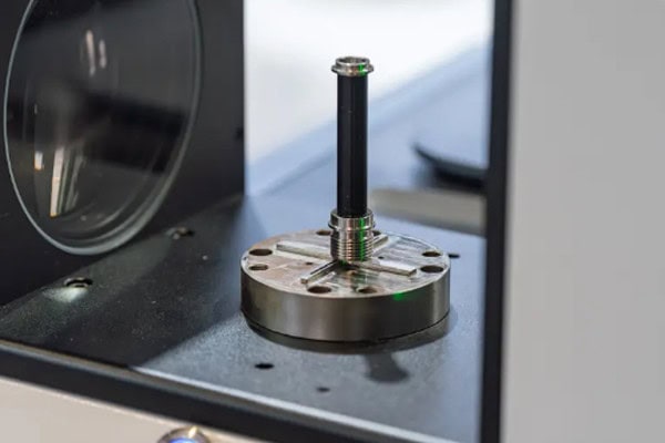
Visual inspection is a basic step, but it is useful before dimensional measurement. Dents, burrs, cracks, chipped edges, and obvious machining marks can often be identified quickly. If the part already has visible defects, there is little value in immediately carrying out detailed dimensional inspection.
During this initial check, look for:
- Obvious burrs or chipped edges around the part.
- Scratches, dents, or unusual marks on machined surfaces.
- Visible defects around holes, grooves, or thin-wall areas.
- Any obvious deformation of the overall part shape.
This inspection is mainly used to identify visible problems. It does not mean the part has passed final inspection. Many precision issues are hidden in dimensions and positional relationships and require professional measuring equipment.
Clean the Part Before Measuring
Oil film and small machining chips can create additional gaps between the measuring tool and the workpiece. When measuring a hole, even a small piece of residue can affect the reading. Particles on a flat surface can also interfere with flatness measurements.
Before measurement, the part is normally prepared by:
- Removing oil and remaining machining chips from the surface.
- Checking whether burrs are present around the measurement area.
- Cleaning the contact surfaces of the measuring tool and workpiece.
Once the part is clean, it becomes much more suitable for precision measurement. This step is particularly important when the specified tolerance is very tight.
Pay Attention to Part and Environmental Temperature
Metal dimensions can change slightly with temperature. This may not matter much for conventional components, but it becomes more important when working with tight tolerances.
A part that has just come off the machine may still be warmer than the inspection environment. Measuring it immediately can produce results that differ slightly from those obtained after the part has cooled and stabilized. Allowing the part and inspection environment to reach a relatively stable temperature can improve measurement reliability.
How Should Different Dimensions Be Measured?
Precision machined parts contain much more than simple length and diameter dimensions. Outside diameters, internal holes, depths, steps, and groove widths all require suitable measuring methods. A common mistake is assuming that a coordinate measuring machine should be used for everything simply because it can measure many features. That is not always the most efficient approach. Simple dimensions can often be checked faster with appropriate hand tools, while more complicated features can be inspected with advanced measurement equipment.
Outside Diameter and Thickness: Micrometers Are Often Suitable
For shafts, cylindrical features, and thickness measurements, micrometers are commonly used on the shop floor. They provide finer measurement capability than standard calipers and are suitable for components with tighter dimensional requirements.
During measurement, the tool needs to be properly aligned with the workpiece, and excessive measuring force should be avoided. Thin-wall parts are particularly sensitive because excessive pressure can slightly change the part shape and affect the measurement result.
Internal Holes: Diameter Is Not the Only Concern
Hole machining is extremely common in precision components, but checking an internal hole is not simply a matter of confirming its diameter. Roundness, depth, axis position, and the relationship between multiple holes can all affect assembly.
Common inspection items include:
- Whether the hole diameter falls within the specified tolerance.
- Whether the hole depth meets the drawing requirement.
- Whether the roundness is within the permitted range.
- Whether the positional relationship between multiple holes is accurate.
Basic hole diameters can be measured with internal measuring tools. For complex structures or holes with strict positional requirements, coordinate measuring machines and other precision equipment are often more appropriate.
Length, Steps, and Groove Widths: Choose the Tool Based on the Feature
Different structures call for different measuring methods. Simple lengths can be checked with calipers, stepped dimensions may require a height gauge, and fine groove widths may need specialized measuring tools.
There is no need to assume that the most advanced instrument is automatically the best choice. The practical approach is to match the inspection tool to the actual feature, maintaining measurement reliability while keeping inspection efficient.
Which Precision Problems Cannot Be Seen with the Naked Eye?
Many problems with precision components do not appear directly on the surface. A part may look clean and well machined, and its individual dimensions may seem acceptable, yet assembly can still reveal uneven gaps, misaligned axes, or incorrect positioning. These issues fall into the category of geometric accuracy and require specialized inspection methods. For high-precision machining, these measurements can directly affect the final assembly result.
How Is Flatness Inspected?
Flatness describes how closely a surface conforms to a flat plane. Mounting plates, bases, and precision support components often have flatness requirements. Even slight warping can cause local gaps or poor contact after assembly.
Common inspection methods include:
- Using a height gauge together with a precision surface plate.
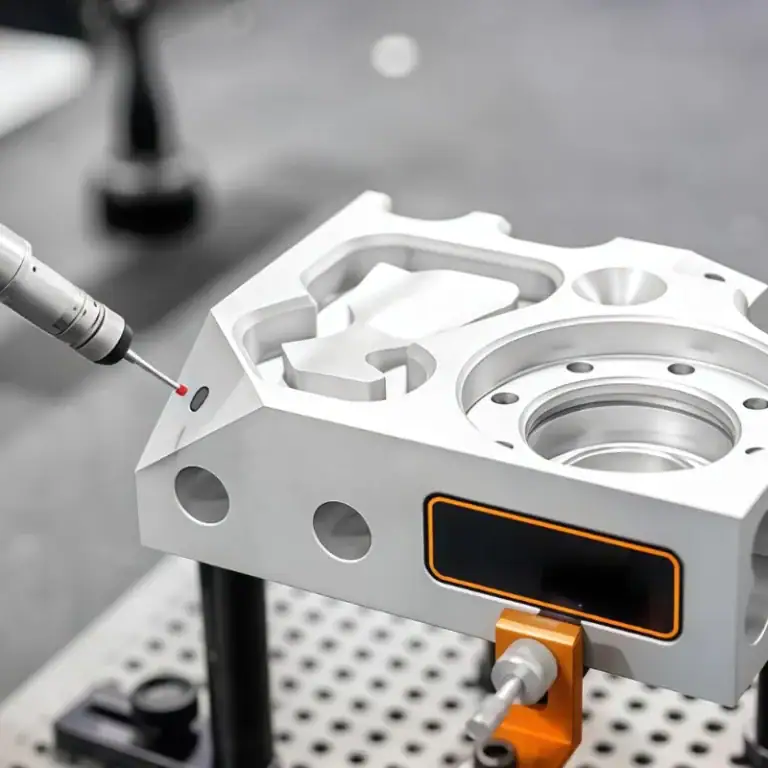
- Using a coordinate measuring machine to collect multiple measurement points.
- Performing dedicated flatness evaluation for parts with demanding accuracy requirements.
A well-planned measurement pattern makes it easier to identify local deformation instead of checking only a few points and assuming the entire surface is acceptable.
Coaxiality and Position Accuracy Can Be Difficult to Detect
Shafts, sleeves, and components with multiple holes can be particularly sensitive to the relationship between different axes. Checking every individual dimension and finding them within tolerance does not necessarily guarantee successful assembly because the positional relationship between features also matters.
This type of inspection often requires coordinate measuring equipment to measure multiple features within the same reference system. The measured results can then be compared with the drawing requirements, making hidden geometric deviations much easier to identify.
Surface Roughness Also Requires Dedicated Inspection
A surface that feels smooth does not necessarily meet the required roughness specification. Different machining processes leave different surface textures, while sealing surfaces, sliding surfaces, and mating surfaces often have specific roughness requirements.
A surface roughness tester can directly measure the relevant parameters. For precision machined parts, this provides a more reliable way to confirm surface condition instead of relying only on visual inspection.
How Should the Final Inspection Process Be Organized?
Reliable inspection is not simply about randomly measuring a few dimensions after production. If a drawing contains more than a dozen critical features but only two or three are checked, the inspection data may not accurately represent the actual condition of the part. This becomes even more important in batch production, where dimensions may gradually shift as tools wear or machine conditions change. One accepted part does not automatically mean every subsequent part will be identical.
List the Critical Dimensions on the Drawing
Before inspection begins, identify the key dimensions, tolerances, and special requirements on the drawing and assign appropriate measuring tools to them. Not every dimension has the same importance, so every feature does not need to be inspected in exactly the same way.
Priority can be given to:
- Dimensions that directly affect assembly.
- Critical features with tight tolerances.
- Hole positions, flatness, and positional accuracy.
- Surface roughness requirements.
Once inspection requirements are clearly organized, inspectors can follow a consistent process and review the results more easily.
Batch Parts Should Not Be Checked Only at the End
During batch precision machining, tool wear, thermal stability, and changes in machining conditions can gradually shift dimensions. If only the first and last parts are inspected, variations occurring in the middle of production may be missed.A more reliable approach is to arrange suitable sampling and critical-dimension checks during production. If measurements begin approaching the tolerance limit, the machining condition can be checked before the deviation spreads to a larger number of parts.
Keep Inspection Records
Inspection records are not simply extra paperwork. They make it easier to trace problems later. If a batch of parts encounters assembly issues, complete measurement records can help determine whether the cause is dimensional accuracy, material changes, or another production factor.For precision components produced over a long period, keeping measurement results can also reveal recurring dimensional trends. Over time, this information becomes useful for improving machining stability and production control.
Inspection of precision machined parts is much more than simply “measuring the dimensions.” Appearance, cleanliness, temperature, basic dimensions, hole positions, geometric tolerances, and surface roughness can all affect the final result. Small-batch parts can use flexible inspection methods, while batch production requires greater attention to in-process sampling and data records. Matching the right measuring tools to simple dimensions, using coordinate measuring machines for complex features, and maintaining complete inspection records can make the manufacturing process more transparent and help identify problems earlier. Tirapid specializes in precision machining services, providing CNC milling, precision turning, and custom machining support for industrial components.