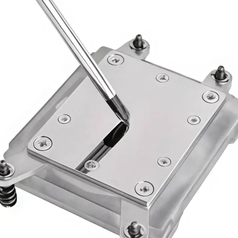
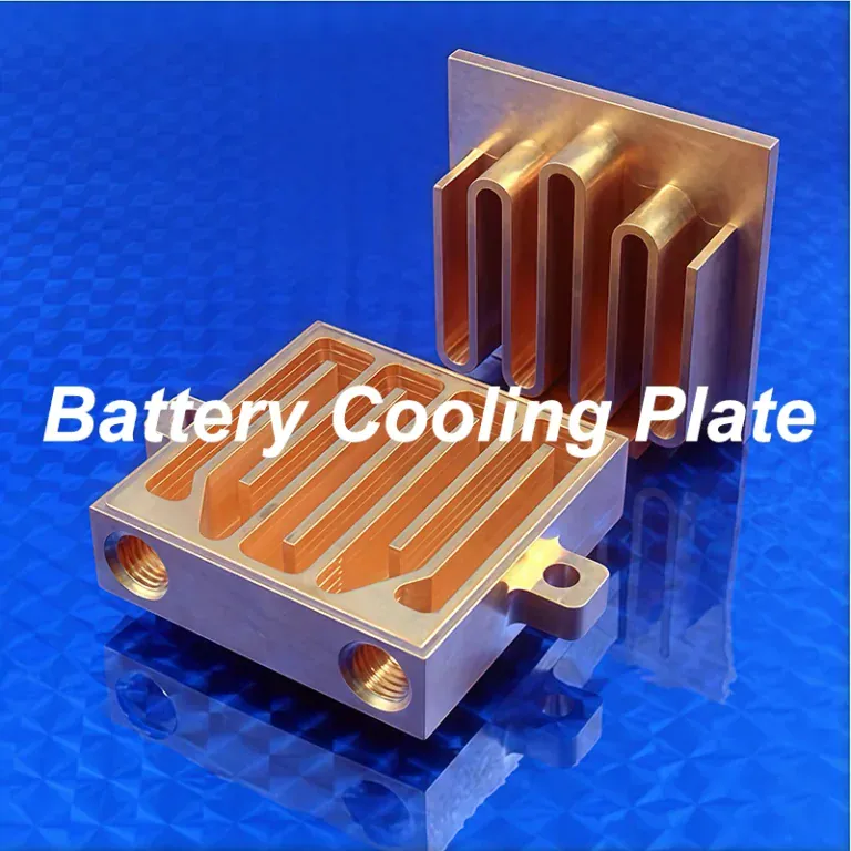
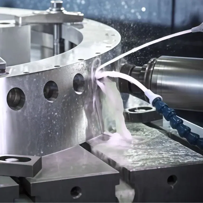
A water cooling block is a precision cooling component that transfers heat from a CPU, GPU, or other electronic device into circulating liquid. It typically uses a copper or aluminum base, internal microfins, and sealed coolant passages to remove heat from concentrated electronic sources. The block works as part of a complete liquid cooling system rather than operating as a standalone cooler.
This guide explains the main types of water cooling blocks, how they work, and the materials used in their construction. It also covers internal components, thermal performance, CNC machining methods, sealing requirements, quality inspection, and practical selection considerations.
What Is A Water Cooling Block?
A water cooling block is a liquid-cooled heat transfer component that absorbs heat from electronic hardware and transfers it into flowing coolant. It is commonly installed on CPUs, GPUs, and other high-power components to maintain suitable operating temperatures.
Unlike a traditional air heatsink, which transfers heat directly into surrounding air, a water block moves heat into a liquid circuit. The coolant then carries that energy to a radiator or another heat exchanger, where it is released into the surrounding environment.
The terms water block, cooling block, and water cooling block generally describe the same type of component in PC cooling applications. However, a water block is only one part of a complete cooling assembly. Its effectiveness depends on material conductivity, thermal contact, coolant flow, and the capacity of the connected cooling loop.
Water blocks are especially useful when electronic components generate high heat loads in limited spaces. Their compact construction allows heat to be collected close to the source, while the radiator and fans can be positioned elsewhere in the computer or equipment enclosure.
How Does A Water Cooling Block Work?
A water cooling block works by conducting heat from an electronic component into a metal base and transferring that heat into circulating coolant through internal channels. The warmed coolant then flows to a radiator, releases heat, and returns to the block.
This process combines solid conduction, liquid convection, and continuous circulation. The block collects heat, while the surrounding cooling system transports and rejects it.
Heat Transfer From The Component To The Coolant
Heat moves from the CPU or GPU into the water block through a metal contact surface. Thermal paste or another suitable interface material fills microscopic surface gaps, reducing the contact resistance between the heat source and the cooling base.
Inside the block, narrow channels and microfins increase the surface area exposed to the flowing coolant. Heat passes through the metal and into the liquid by convection. Channel geometry and material conductivity influence how effectively this transfer occurs.
For example, a processor producing 250 W creates a continuous cooling requirement when operating at that power level. The water block must transfer this heat into the liquid without allowing the processor temperature to exceed its operating limit. Actual performance also depends on coolant temperature and contact quality.
How A Complete Water Cooling System Works
A complete water cooling system includes a water block, pump, radiator, tubing, fittings, and coolant. A custom loop commonly includes a reservoir, while an all-in-one cooling assembly may integrate several functions into a sealed unit.
The pump moves coolant through the block and the radiator. After absorbing heat from the electronic component, the liquid passes through the radiator, where airflow removes energy before the coolant returns to the block.
The main system components perform different functions:
| Component | Main Function |
| Water Block | Transfers heat from electronics to coolant |
| Pump | Circulates liquid through the loop |
| Radiator | Transfers heat from coolant to air |
| Fans | Move air through the radiator |
| Reservoir | Provides fluid storage and helps with filling and air management |
| Tubing And Fittings | Connect the cooling components |
| Coolant | Carries thermal energy through the system |
A computer water cooling system must balance flow resistance, pump capacity, radiator performance, and heat generation. Even an efficient water block cannot maintain suitable temperatures if the radiator is undersized or coolant circulation is insufficient.
What Are The Main Types Of Water Cooling Blocks?
The main types of water cooling blocks are CPU blocks, GPU blocks, monoblocks, and specialized blocks for RAM or voltage regulation modules. They can also be classified as universal or device-specific designs, depending on their mounting compatibility.
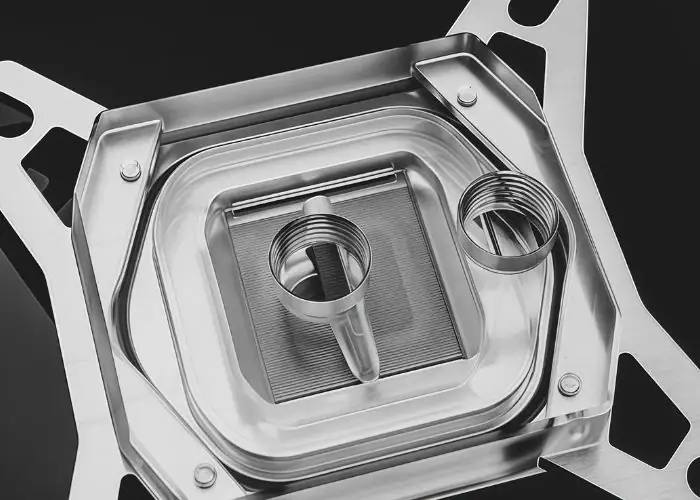
Each type is designed around the geometry and thermal requirements of the component being cooled. The differences affect contact surfaces, mounting layouts, internal channels, and manufacturing complexity.
CPU Water Blocks
CPU water blocks transfer heat from a computer processor into circulating coolant. Their base normally contacts the processor’s integrated heat spreader, using thermal paste to reduce gaps between the two surfaces.
Most CPU blocks use a copper or nickel-plated copper base with internal microfins. The cooling structure concentrates heat removal near the processor’s main thermal region. Mounting hardware controls the contact pressure and maintains the required alignment.
Compatibility depends on the processor socket and mounting arrangement. A custom water cooling PC design must account for mounting-hole spacing, bracket geometry, component clearance, and the available space around the processor.
GPU Water Blocks
GPU water blocks remove heat from graphics processors and, in some designs, other components on the graphics card. They are particularly important in GPU liquid cooling systems where graphics cards operate under sustained computational loads.
A full-coverage GPU block typically contacts the graphics processor, video memory, and selected voltage regulation components. It uses thermal paste and pads of specified thicknesses to establish the required thermal interfaces.
These blocks often have complex contours, multiple contact heights, and precisely positioned mounting holes. Their manufacturing requires accurate CNC machining because even graphics cards using the same GPU chip may have different circuit-board layouts.
Monoblocks, RAM, And VRM Water Blocks
Monoblocks combine multiple cooling interfaces within one assembly. Depending on the design, they may cool a CPU and nearby motherboard voltage regulation components, reducing the number of separate water blocks required.
RAM water blocks and dedicated VRM blocks provide liquid cooling for other electronic components. They are generally used in specialized systems where high thermal loads, packaging constraints, or particular performance requirements justify additional cooling hardware.
These designs can require stepped contact surfaces, complex mounting arrangements, and internal flow passages serving several heat sources. Engineers must consider the height of each component and the appropriate thermal interface thickness.
Universal Vs. Device-Specific Water Blocks
Universal water blocks are designed to fit multiple devices within a defined compatibility range. They usually focus on a particular heat source and may require separate cooling for adjacent components.
Device-specific blocks are designed around a particular processor socket, graphics-card circuit board, or electronic assembly. This allows more complete contact coverage but limits interchangeability when the hardware changes.
| Water Block Type | Main Cooling Target | Compatibility | Manufacturing Complexity |
| CPU Block | Processor | Socket-dependent | Moderate |
| Full-Cover GPU Block | GPU, memory, selected VRMs | Specific circuit board | High |
| Universal GPU Block | GPU chip | Wider, but still limited | Moderate |
| Monoblock | Multiple components | Specific motherboard or assembly | High |
| RAM / VRM Block | Memory or power circuitry | Module-dependent | Low to moderate |
For custom manufacturing projects, compatibility should be confirmed using actual component drawings rather than relying only on product names.
What Are The Key Components Of A Water Cooling Block?
A water cooling block consists of a conductive base plate, internal cooling channels, a top cover, coolant ports, seals, and mounting hardware. Each component contributes to heat transfer, mechanical stability, or fluid containment.
The block’s construction must balance thermal performance with assembly accuracy and leakage resistance. Even when the external shape is simple, internal features can be difficult to manufacture consistently.
Base Plates And Microfin Channels
The base plate collects heat from the electronic component and distributes it toward the coolant passages. Copper is commonly used because of its high thermal conductivity, while aluminum can provide a lighter and more economical alternative.
Microfins create narrow passages that increase the available heat-transfer surface. Their height, thickness, spacing, and orientation influence thermal performance and coolant resistance.
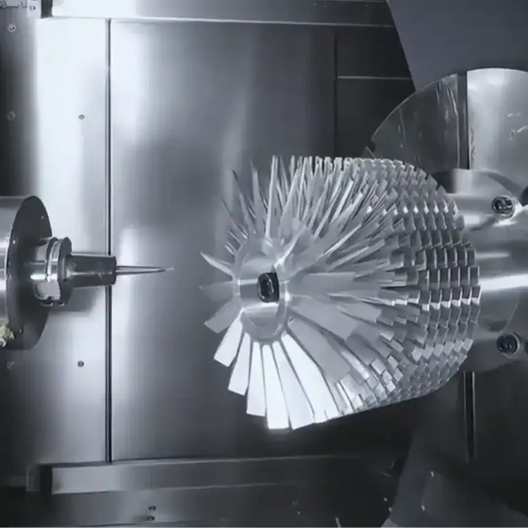
Manufacturing these features requires suitable cutting tools and process control. Thin fins may bend or develop burrs during CNC milling. Excessive variation in channel geometry can also affect local flow distribution.
Top Covers, Ports, And Seals
The top cover closes the coolant passages and supports the inlet and outlet connections. It can be manufactured from metal, acetal, acrylic, or other compatible materials, depending on the design.
Coolant ports connect the block to tubing or fittings. Their threads and sealing interfaces must match the specified connection standard, while internal passages should avoid unnecessary restrictions.
O-rings or other compatible seals prevent fluid from escaping between the cover and base. Groove depth, surface finish, and fastener loading must be controlled to achieve suitable compression without damaging the sealing components.
Mounting Hardware And Thermal Interfaces
Mounting brackets, screws, standoffs, and springs secure the block to the electronic assembly. They determine how pressure is distributed across the thermal contact surface.
Thermal paste or pads compensate for small surface irregularities and differences in component height. The correct material and thickness depend on the device, contact pressure, and thermal requirements.
Poor mounting can reduce cooling performance even when the internal water channels are well designed. Excessive force may damage the processor package or circuit board, while insufficient force can leave gaps and increase thermal resistance.
What Materials Are Used For Water Cooling Blocks?
Water cooling blocks commonly use copper, nickel-plated copper, or aluminum for the heat-transfer base. Acrylic, acetal, and metals are used for covers, while elastomeric seals prevent coolant leakage. Material selection affects thermal performance, corrosion resistance, cost, and CNC machinability.
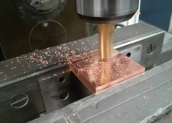
Copper and aluminum are the main heat-transfer materials, but they must be evaluated together with the coolant and other wetted components. Cover materials are selected for structural, sealing, and appearance requirements.
Copper And Nickel-Plated Copper
Copper is widely used for water block bases because its thermal conductivity is relatively high. Common high-conductivity copper grades can approach approximately 390 W/(m·K) at room temperature, depending on purity and condition.
Nickel plating provides a protective surface and a consistent appearance on suitable copper components. However, the plating is not a replacement for proper coolant chemistry or material compatibility. Coating thickness and coverage must also be considered during manufacturing.
Copper CNC machining requires attention to burr formation, tool adhesion, and surface finish. Closely spaced fins and narrow channels can be challenging because the metal’s ductility may produce unwanted edge deformation during cutting.
Aluminum Water Cooling Blocks
Aluminum water cooling blocks offer lower weight, relatively low material cost, and good machining efficiency. An aluminum base can be attractive for custom electronic equipment where weight and manufacturing economy are priorities.
For comparison, 6061 aluminum has a typical room-temperature thermal conductivity of approximately 167 W/(m·K). Although this is lower than copper, an aluminum water cooling block can still perform effectively when its geometry and coolant flow are properly designed.
Aluminum components should not be combined casually with exposed copper or brass in the same liquid loop. Mixed wetted metals can create galvanic corrosion risks when the coolant is sufficiently conductive. A compatible, protected system must be designed and validated before use.
Cover Materials And Galvanic Corrosion Risks
Water block covers are commonly made from acrylic, acetal, aluminum, copper, or brass. Acrylic provides visibility into internal passages, while acetal offers good toughness and useful chemical resistance for compatible coolant conditions.
Acrylic can crack under excessive fastening loads and may be damaged by certain cleaners. Acetal is generally more resistant to cracking, but its threads can still be damaged by overtightening.
The selection of cover materials must also consider which surfaces contact the coolant. Dissimilar metals, coating defects, and unsuitable coolant chemistry can contribute to corrosion or deposits that obstruct narrow channels.
| Material | Typical Application | Main Advantage | Important Limitation |
| Copper | Heat-transfer base | High thermal conductivity | Weight, cost, machining burrs |
| Nickel-Plated Copper | Heat-transfer base | Protective finish and appearance | Coating quality and compatibility |
| Aluminum | Base or housing | Lightweight and machinable | Mixed-metal corrosion risk |
| Acrylic | Transparent top cover | Visible internal channels | Brittle under excessive stress |
| Acetal (POM) | Top cover or housing | Toughness and machinability | Thread damage if overtightened |
What Affects Water Cooling Block Performance?
Water cooling block performance depends on microfin geometry, coolant flow, pressure drop, material conductivity, surface flatness, and mounting pressure. These factors determine how effectively heat moves from the electronic device into the circulating liquid.
The best design balances heat transfer with flow resistance and manufacturing practicality. A more complicated channel pattern does not automatically provide better overall cooling.
Microfin Geometry And Heat Transfer Efficiency
Microfin geometry determines how much metal surface contacts the coolant and how fluid moves across the heated region. Fin thickness, channel width, depth, and spacing all influence heat transfer.
Narrower passages can increase the heat-transfer surface area within a compact base. However, they may also increase pressure drop and make the block more sensitive to contamination or restricted flow.
Engineers must balance thermal benefit against manufacturing limits. Very thin fins can deform during machining, while very narrow channels may require specialized cutters and more demanding inspection methods.
Coolant Flow Rate And Pressure Drop
Coolant flow rate affects the amount of heat transported through the water block. The relationship between flow and temperature rise can be estimated using the coolant’s mass flow rate and specific heat capacity.
For example, at a steady 250 W heat load and 1 L/min of water flow, the theoretical coolant temperature rise is approximately 3.6°C. This does not represent the temperature difference between the processor and the coolant.
Pressure drop increases as coolant encounters narrow channels, sharp turns, and other restrictions. The pc water cooling pump must provide sufficient flow at the resistance of the complete loop. Higher flow may improve thermal performance, but additional pumping effort can have diminishing benefits.
Surface Flatness, Contact Pressure, And Thermal Resistance
Surface flatness affects how well a water block contacts the heat-generating component. An uneven base can create local gaps and increase resistance to heat transfer.
Thermal interface material reduces the effect of microscopic irregularities, but excessive thickness can increase resistance. Mounting pressure must be distributed consistently without damaging the processor or circuit board.
A simple thermal resistance relationship is ΔT = Q × Rθ, where Q is heat load and Rθ is thermal resistance. At 200 W and 0.10 K/W, the corresponding temperature difference is 20°C. The reference temperatures must be defined before comparing blocks.
How Are Water Cooling Blocks CNC Machined?
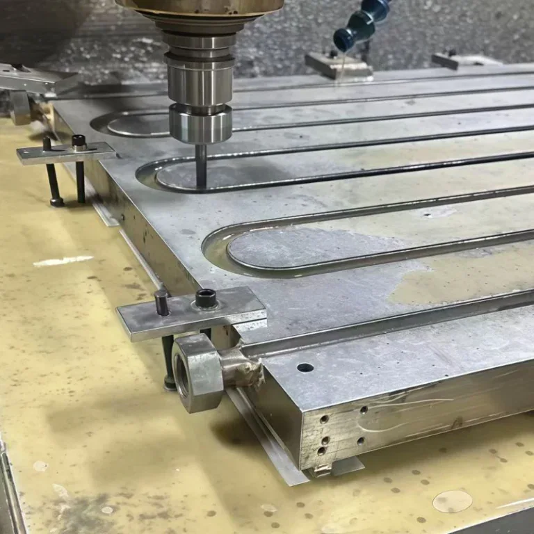
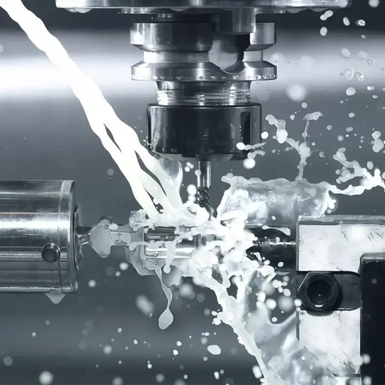
Water cooling blocks are CNC machined by milling conductive base plates, forming internal channels, drilling connection ports, and machining sealing and mounting features. Precision finishing, deburring, cleaning, and dimensional inspection help ensure that the parts fit correctly and support reliable cooling.
CNC machining is especially valuable for custom water blocks that require unusual dimensions, complex internal flow paths, or precise interfaces. The machining process must balance cooling performance, production cost, and component reliability.
CNC Milling Of Base Plates And Microchannels
CNC milling is used to create the water block base, coolant passages, microfins, and distribution cavities. The toolpath must follow the intended channel geometry while preserving enough material for strength and heat conduction.
Copper bases can require sharp cutting tools and suitable machining conditions to reduce burr formation. Aluminum permits efficient material removal, but thin channel walls can still deform when cutting forces become excessive.
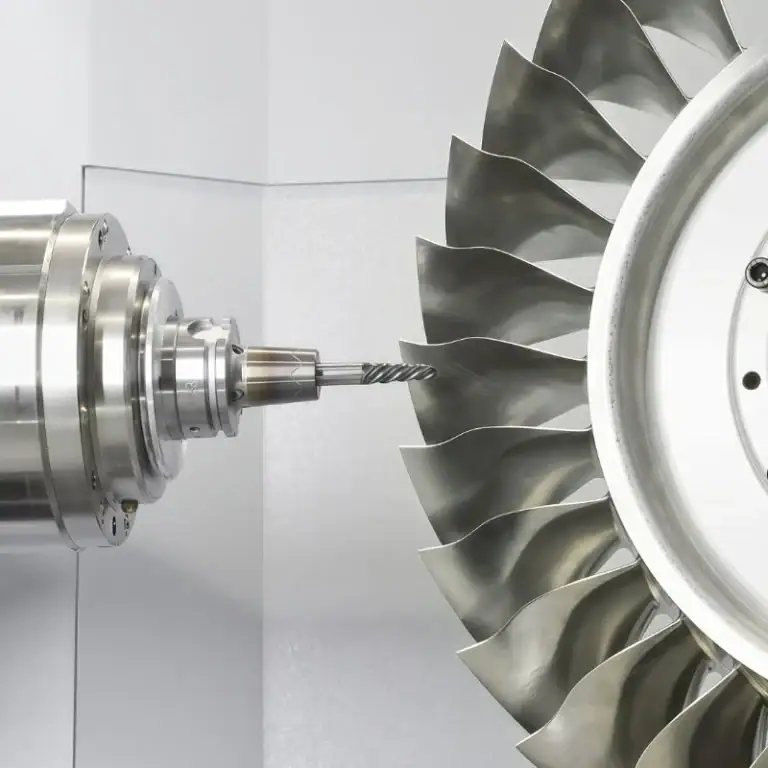
For complex custom designs, multi-axis machining can produce angled ports, intersecting features, and mounting surfaces with fewer setups. Very narrow microchannels require additional planning because tool deflection and chip evacuation can affect dimensional consistency.
Precision Machining Of Ports, Mounting Features, And Sealing Grooves
Ports, mounting holes, and sealing grooves must be accurately positioned because they determine assembly fit and leakage resistance. Threaded connections should match the intended fittings rather than relying on generic dimensions.
O-ring grooves require appropriate width, depth, and surface finish. Incorrect groove geometry may create inadequate compression or damage the seal when the cover is assembled.
The main machining priorities include:
- Channel Consistency:Maintain the required width, depth, and fin geometry.
- Port Accuracy:Produce compatible threads and sealing interfaces.
- Mounting Position:Control hole spacing and alignment with electronic components.
- Sealing Geometry:Maintain the specified groove profile and contact surfaces.
- Tool Access:Avoid unnecessarily deep features that require unstable cutting tools.
Critical dimensions must come from the approved engineering drawing. Tight tolerances should be applied to functional interfaces rather than unnecessarily increasing the cost of the entire part.
Surface Finishing, Deburring, And Cleaning
Surface finishing improves the condition of contact faces and other critical machined areas. The required flatness and surface texture should reflect the actual thermal interface design rather than a universal polishing requirement.
Deburring is particularly important for internal cooling channels. Loose metal fragments can obstruct narrow passages, damage seals, or contaminate the pump and other cooling components.
Cleaning methods must remove machining fluids, chips, and other residues without damaging the material or protective coating. The final cleaning procedure should be compatible with copper, aluminum, plated surfaces, and any assembled polymer components.
Dimensional Inspection And Leak Testing
Dimensional inspection verifies the water block’s base geometry, channel dimensions, hole positions, sealing grooves, and critical assembly interfaces. Suitable equipment may include coordinate measuring machines, precision gauges, and surface measurement tools.
For high-precision components, parts should reach an appropriate measurement temperature before final inspection. This reduces errors caused by thermal expansion after machining.
After assembly, the complete cooling block should undergo an appropriate leak or pressure test. The specified pressure, test duration, and acceptance criteria depend on the product design. Machining inspection alone cannot demonstrate that an assembled fluid-containing component is leak-tight.
What Are The Advantages And Limitations Of Water Cooling Blocks?
Water cooling blocks provide compact heat collection, flexible system integration, and effective cooling for concentrated electronic loads. Their limitations include the need for pumps, radiators, sealed connections, maintenance, and additional manufacturing or installation costs.
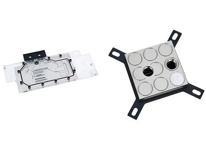
Their practical value depends on the complete cooling system. A high-performance water block will not guarantee low device temperatures unless coolant circulation, radiator capacity, and thermal contact are also suitable.
Cooling Performance, Noise, And Space Advantages
Water blocks transfer heat from crowded electronic regions to a remotely positioned radiator. This reduces the need for a large heatsink directly above the processor or graphics card.
Water cooling can improve thermal management during sustained high-power operation when the loop is properly sized. A large radiator may also allow lower fan speeds under some conditions, although the pump introduces its own noise.
Custom block geometry provides flexibility in equipment integration. Manufacturers can adapt contact surfaces, port positions, and flow channels to the available space, making water blocks useful for specialized electronics and compact machinery.
Leakage Risks, Maintenance, And Cost Limitations
Water cooling systems introduce fluid connections, pumps, and other components that require maintenance. Leaks, corrosion, and channel blockage can damage equipment or reduce cooling performance.
Coolant selection and cleanliness are important because deposits can accumulate between microfins. Poorly maintained loops may experience rising flow resistance and declining thermal performance over time.
Water cooling block price varies with the material, internal geometry, device compatibility, machining complexity, and assembly requirements. Custom copper blocks with fine channels and precision sealing interfaces generally involve more manufacturing work than simple aluminum components.
Water Blocks Vs. AIO Liquid Coolers And Air Heat Sinks
A standalone water block is one component of a liquid cooling loop. An all-in-one liquid cooler is a preassembled cooling system that typically integrates a block, pump, radiator, tubing, and coolant.
Air heatsinks use metal fins and airflow to transfer heat from the component into the surrounding air. They are often simpler to install and maintain, while liquid systems allow more flexible placement of the final heat rejection hardware.
| Cooling Option | Main Advantage | Main Limitation | Suitable Application |
| Custom Water Block And Loop | Flexible design and expansion | Complex installation and maintenance | Custom PCs and specialized equipment |
| AIO Liquid Cooler | Integrated, convenient assembly | Limited customization | Standard CPU cooling |
| Air Heatsink | Simple and relatively economical | Space and airflow requirements | General-purpose PCs |
The best option depends on available space, heat load, noise targets, maintenance preferences, and total cost rather than cooling technology alone.
How Do You Choose The Right Water Cooling Block?
The right water cooling block should match the electronic component, required cooling load, coolant loop, material compatibility, and available installation space. Engineers should also consider whether a standard product is sufficient or a custom CNC-machined design is needed.
Selection should begin with mechanical compatibility and thermal requirements. A block with excellent heat-transfer capability cannot work correctly if it does not fit the component or connect safely to the cooling loop.
CPU Socket And GPU Compatibility
CPU block compatibility depends on socket geometry, mounting-hole spacing, retention hardware, and clearance around the processor. Manufacturers should verify the exact socket generation and approved mounting kit.
GPU compatibility is more complicated because graphics cards can use different circuit-board layouts even when they contain the same graphics processor. Full-cover blocks must match the locations and heights of the GPU, memory, and voltage regulation components.
Engineers should use manufacturer compatibility information or actual hardware drawings before choosing a block. Incorrect thermal pad thickness or mounting geometry can prevent proper contact and create excessive mechanical stress.
Standard Vs. Custom Water Cooling Blocks
Standard blocks are suitable when existing products match the device geometry, flow requirements, and installation space. They can reduce engineering time and usually avoid the cost of developing a new component.
Custom water blocks are useful when the heat-source layout, mounting interface, or enclosure geometry differs from standard designs. Custom pc water cooling applications may also require unusual port positions or integration with multiple electronic components.
CNC machining makes it possible to create customized copper and aluminum bases, channels, and mounting features. The design should be reviewed for tool accessibility, wall thickness, sealing reliability, and practical inspection before production.
Material, Connection, And Manufacturing Considerations
Material selection should account for thermal conductivity, coolant compatibility, structural requirements, and cost. Copper is often chosen for compact high-performance bases, while aluminum can be attractive for lightweight and cost-sensitive designs.
Connection design must match tubing, fittings, and the intended coolant loop. Material combinations should be evaluated to avoid galvanic corrosion, while suitable seals and accessible mounting features simplify assembly.
Manufacturing decisions also affect long-term reliability. Fine channels can improve heat-transfer area but increase machining difficulty and cleaning requirements. Early DFM analysis helps balance thermal performance, dimensional accuracy, manufacturing cost, and expected production volume.
FAQs
How Do Water Blocks Remove Heat In Liquid Cooling?
Water blocks remove heat through conduction and convection. A metal base receives heat from the CPU or GPU, while internal fins transfer that energy to circulating coolant. The liquid then carries heat to a radiator for rejection. For example, water flowing at 1 L/min can absorb 200 W with an ideal temperature rise of approximately 2.9°C. Actual device temperature also depends on the base material, contact resistance, channel geometry, and the cooling loop’s capacity.
How Do Water Cooling Blocks Work On GPUs?
GPU water blocks transfer heat from a graphics processor and, in full-cover designs, selected memory and voltage regulation components into liquid coolant. Thermal paste contacts the GPU die, while pads accommodate height differences on other components. The metal base conducts heat into internal channels, where flowing liquid absorbs it. A graphics card producing 300 W requires the complete cooling system to remove approximately that heat at steady state. Correct contact, flow distribution, and radiator capacity determine the resulting temperatures.
How To Apply A Water Cooling Block On A GPU?
To install a GPU water block, first confirm that it matches the exact graphics card model and circuit-board layout. Remove the original cooling assembly according to the manufacturer’s instructions, clean the contact surfaces, and apply the specified thermal paste and pad thicknesses. Position the block carefully and tighten mounting screws using the required sequence and torque. Check clearances, connect the coolant lines, and perform a suitable leak test before normal operation. Incorrect pad thickness can prevent contact with the GPU die.
What Can I Use To Clean A Water Cooler Block?
Use the cleaning method recommended for the block’s materials and surface coatings. Disassembled bare copper components may be cleaned with compatible products and a soft brush, followed by thorough rinsing and drying. Acrylic covers should not be exposed to aggressive solvents, including alcohol where the manufacturer warns against it. Avoid abrasive tools that damage nickel plating or sealing surfaces. After cleaning, inspect microfins, seals, and ports for debris or wear. Reassemble the block with suitable seals and verify leakage resistance.
Conclusion
A water cooling block transfers heat from electronic components into circulating coolant through a conductive base and internal channels. Its performance depends on the block type, material, microfin geometry, coolant flow, and contact quality. Copper and aluminum offer different advantages, while CNC machining enables accurate channels, sealing grooves, and mounting interfaces. Engineers must also consider corrosion, device compatibility, manufacturing costs, dimensional inspection, and leakage control when developing reliable cooling components.
At TiRapid, we provide precision CNC machining and manufacturing services for custom copper and aluminum components. Our CNC milling, turning, multi-axis machining, DFM support, and dimensional inspection help customers produce accurate cooling channels, mounting features, sealing interfaces, and other precision parts for demanding thermal management applications.