Turbo impellers are high-speed rotating components whose performance depends heavily on blade geometry, mass distribution, surface condition, and the relationship between the hub and rotational axis. Small machining errors can change airflow, increase vibration, reduce compressor efficiency, or make final balancing more difficult.
This guide explains how turbo impeller machining moves from design and material selection through 5-axis CNC roughing, blade finishing, CAM toolpath control, balancing, and final inspection. It also covers the machining risks that affect blade accuracy, surface finish, dimensional consistency, and repeatable production quality.
What Is A Turbo Impeller?
A turbo impeller is a high-speed rotating wheel with multiple curved blades designed to accelerate and compress incoming air. In turbocharger applications, its aerodynamic geometry and rotational accuracy directly influence airflow, boost response, efficiency, and vibration, which makes precision machining especially important.
How Do Turbo Impellers Work?
A turbo impeller, often called a compressor wheel, rotates at very high speed and draws air into the center of the wheel. The curved blades accelerate the air outward toward the larger outside diameter.
As air leaves the impeller, velocity is converted into increased pressure through the surrounding compressor geometry. The compressed air can then be supplied to the engine at a higher density.
Because the blades control how air enters, accelerates, and exits the wheel, blade shape cannot be treated as a decorative surface. Profile accuracy and consistency from one blade to the next are functional requirements.
What Are the Main Features of A Turbo Impeller?
The main features include the hub, center bore or shaft interface, blade roots, leading edges, trailing edges, blade tips, and flow channels between adjacent blades.
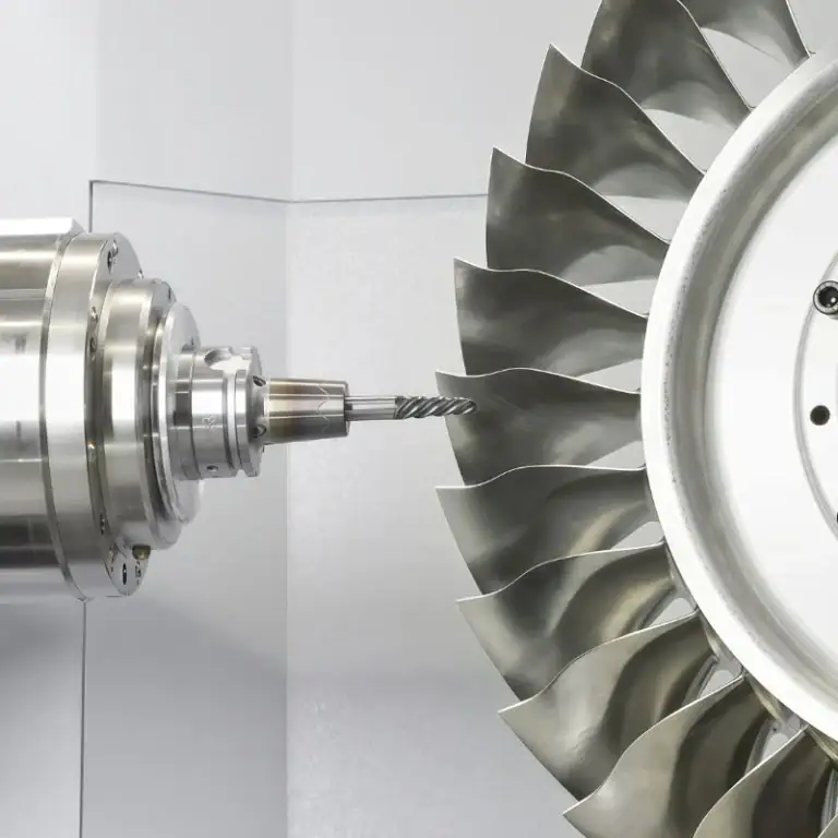
Many turbo impellers use three-dimensional twisted blades whose angle and curvature change from the inlet toward the outside diameter. This geometry creates narrow spaces that are difficult to reach with conventional three-axis milling.
The center bore and hub are equally important. Even if every blade is machined correctly, poor bore concentricity or excessive runout can shift the rotating mass away from the intended axis.
Why Does Machining Accuracy Matter At High Speed?
At high rotational speed, small geometric and mass errors can create significant centrifugal forces.
A small difference in blade thickness, uneven stock removal, or an off-center bore may create residual imbalance. Surface defects or abrupt geometry at the blade root can also become local stress concentration points.
Turbo impeller machining must therefore control both dimensions and symmetry. A successful part is not simply one that matches individual dimensions,the entire wheel must behave as one balanced rotating system.
How Does Turbo Impeller Design Affect Machining?
Turbo impeller design directly determines machining difficulty. Blade curvature, thickness, root geometry, inlet and outlet diameters, blade count, and channel width affect tool access, tool length, cutting forces, cycle time, and the risk of interference. A design that performs well aerodynamically must still provide a practical machining route.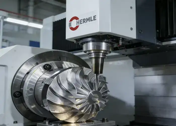
Blade Profile, Curvature, And Angle
Turbo impeller blades normally contain complex freeform surfaces rather than simple constant-angle walls.
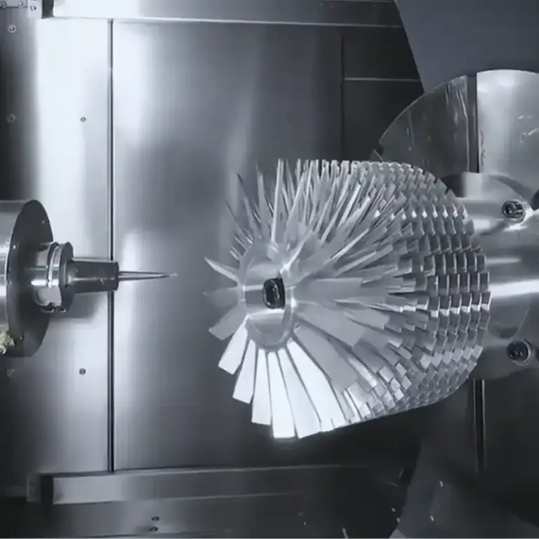
As the tool follows the blade, its orientation must change continuously to maintain contact while avoiding neighboring blades. This is one reason 5-axis simultaneous machining is commonly used for impeller geometry. Hawk Ridge’s CAMWorks example similarly uses 5-axis strategies to rough between blades and finish the curved surfaces while actively controlling the tool axis.
More aggressive curvature generally means more tool-axis movement. This increases CAM programming complexity and makes collision checking more important.
Blade Thickness And Root Geometry
Thin blades reduce rotating mass and support aerodynamic design, but they also reduce part rigidity during machining.
When material is removed from both sides of a thin blade, cutting forces can deflect the remaining section. This may create profile error, taper, vibration marks, or an inconsistent trailing edge.
The blade root requires special attention because it transitions from a thin aerodynamic surface into the much thicker hub. Suitable fillet geometry helps both structural performance and cutter access.
Inlet And Outlet Diameters
The inlet diameter influences the geometry near the blade leading edge, while the outside diameter defines the blade tip region and maximum wheel size.
These dimensions affect how deeply the cutter must enter the flow channels and how much clearance is available between the tool holder and neighboring blades.
Large outside diameters can provide more working space, but they also increase the effect of radial error and mass variation during high-speed rotation.
Blade Count And Channel Width
Adding more blades can reduce the space available between adjacent surfaces.
Narrow channels may require smaller-diameter or longer-reach tools. These tools are less rigid and more sensitive to deflection and chatter.
A dense blade arrangement can therefore increase machining time even if the total impeller diameter remains unchanged. CAM strategy must account for both cutting access and holder clearance.
Rotational Symmetry And Mass Distribution
A turbo impeller is rotationally symmetric in function, so machining should preserve that symmetry as much as possible.
If one blade receives more stock removal than the others, or if tool wear causes a gradual profile change around the wheel, the final mass distribution may become uneven.
Toolpath patterning can help maintain consistency. In the CAMWorks example, one blade region is programmed and then repeated around the impeller using a circular pattern, reducing variation between programmed sectors.
What Materials Are Used For Turbo Impellers?
Turbo impeller materials must balance low rotating mass, strength, temperature resistance, fatigue performance, corrosion resistance, and machinability. Aluminum is common for compressor wheels, while titanium and nickel-based alloys are selected when higher strength or temperature capability justifies additional machining difficulty.
Aluminum Alloys
Aluminum alloys offer low density and good machinability, making them well suited to lightweight compressor impellers.
Their lower cutting forces allow relatively high-speed milling and efficient material removal. This is useful when large amounts of material must be removed between blades.
The main machining risks are thin-blade deflection, burr formation on fine edges, and distortion if the blank or process contains residual stress.
Titanium Alloys
Titanium offers a high strength-to-weight ratio, good corrosion resistance, and useful performance where stronger lightweight components are required.
Ti-6Al-4V is a common titanium grade used for turbine and impeller applications. ForceBeyond, for example, describes titanium turbine impellers produced from Ti-6Al-4V using casting followed by precision 5-axis CNC machining.
Titanium is more demanding to machine than aluminum because cutting heat remains concentrated near the tool edge. Tool selection, cutting speed, coolant delivery, engagement, and tool-life management become more important.
Nickel-Based Alloys
Nickel-based alloys may be selected for high-temperature turbomachinery components where heat resistance is more important than low machining cost.
These materials generate high cutting loads and retain strength at elevated cutting temperatures. Tool wear can therefore increase rapidly if parameters are too aggressive.
For complex impeller blades, long tool engagement combined with difficult material behavior makes controlled cutting conditions essential.
Stainless Steel And Other Materials
Stainless steels may be used where corrosion resistance and mechanical strength are required.
They generally produce higher cutting forces than aluminum and can work-harden if cutting conditions are poorly controlled.
Material selection should always follow the actual turbocharger operating environment rather than machining convenience alone.
Billet, Forged, And Cast Blanks
A machined impeller may start from billet, a forging, or a casting.
Billet machining offers flexibility for prototypes, small batches, and design changes but removes more material. Forgings can provide favorable mechanical properties while reducing excess stock.
Cast or near-net-shape blanks reduce material removal for larger quantities, but the machining plan must account for casting variation and any required material inspection before precision finishing.
Why Is 5-Axis CNC Used For Turbo Impeller Machining?
5-axis CNC machining allows the cutter to reach twisted blades, narrow channels, and changing surface angles while controlling tool orientation continuously. It can reduce re-clamping, improve the relationship between blades and the hub, and make complex impeller geometry practical to machine from a single setup.
Accessing Twisted Blade Surfaces
Turbo impeller blades change orientation from root to tip.
A three-axis machine cannot always maintain a favorable tool angle across these surfaces without repositioning the workpiece.
Five-axis motion allows the tool to tilt while following the blade, keeping the cutting edge in a more effective orientation.
Machining Narrow Blade Channels
The space between blades is one of the most difficult areas to machine.
Tilting the tool allows a shorter effective reach and better access to deep sections of the flow channel.
This can improve tool rigidity and reduce the chance that the holder contacts an adjacent blade.
Reducing Setups And Datum Transfer Error
Multiple setups introduce additional locating error every time the part is re-clamped.
Producing the hub, channels, and blade surfaces within a controlled five-axis setup helps preserve their relationship to the rotational axis.
Fewer setups also simplify inspection because more features can reference the same machining datum system.
Controlling Tool Orientation And Surface Finish
Five-axis machining is not only about reaching difficult surfaces.
Tool orientation determines which part of the cutter contacts the blade. A poor contact point can increase effective cutting speed variation, create marks, or reduce surface quality.
Controlled tilt helps maintain stable cutter engagement across changing blade curvature.
What Is the Turbo Impeller Machining Process?
A typical turbo impeller machining process includes CAD review, blank preparation, datum establishment, hub and bore machining, five-axis roughing, semi-finishing, blade finishing, deburring, and final quality verification. The sequence should maintain enough rigidity during early operations while leaving the most sensitive blade surfaces for controlled finishing.
CAD Model And Machining Review
Machining begins with the approved three-dimensional model and drawing requirements.
The programmer reviews blade curvature, minimum channel width, tool access, hub geometry, bore features, fillet radii, and surfaces requiring final inspection.
At this stage, the goal is to identify areas where tool length, holder clearance, blade flexibility, or cutter interference could create manufacturing risk.
Blank Preparation And Datum Setup
The raw blank is prepared with enough machining allowance for the hub, blade region, and reference surfaces.
Stable datums should be established early. The center axis is especially important because later blade patterning, bore machining, runout inspection, and balancing all depend on the same rotational reference.
Secure workholding is required, but clamping should not introduce distortion into the blank.
Hub, Bore, And Reference Feature Machining
The hub and center bore establish important geometric relationships before blade machining begins.
Depending on the design, the bore may be drilled, bored, reamed, interpolated, or finished in a later operation.
Concentricity between the bore and machined blade system is more important than treating the bore as an isolated diameter.
5-Axis Roughing Between Blades
Roughing removes the majority of material between adjacent blades.
A larger, rigid tool is generally preferred where access permits. The toolpath should maintain safe stock around the blade surfaces and root fillets for later finishing.
Ultirapid describes a similar sequence in which the hub and channels are roughed first, with controlled material left for subsequent precision blade machining.
Semi-Finishing The Blade Channels
Semi-finishing creates a more uniform allowance before the final blade pass.
This step is valuable because finishing tools perform more consistently when they encounter predictable stock rather than large variations left by roughing.
Semi-finishing can also expose local access problems before the final surface is created.
Final Blade And Hub Finishing
Blade finishing uses smaller tools and tighter stepover to follow the final aerodynamic geometry.
Ball-nose or tapered ball-nose tools are commonly suited to curved surfaces and root regions. Ultirapid similarly identifies ball-end tools and simultaneous five-axis movement as key elements in blade finishing.
The finishing strategy should maintain smooth motion and avoid sudden tool-axis changes that can leave marks on the blade.
Deburring And Post-Machining Finishing
After machining, blade edges and accessible transitions are carefully deburred.
The process must remove loose burrs without rounding critical leading or trailing edges beyond the design.
Cleaning, polishing, coating, heat treatment, or other secondary processes are then applied only when required by the material and application.
How Are CAM Toolpaths Planned For Machining Impellers?
CAM programming for machining impellers must control where the cutter contacts the blade, how the tool axis moves, how the tool enters and exits narrow channels, and how collisions are avoided. Toolpath quality directly affects blade geometry, surface finish, machining time, and the risk of damaging an already finished surface.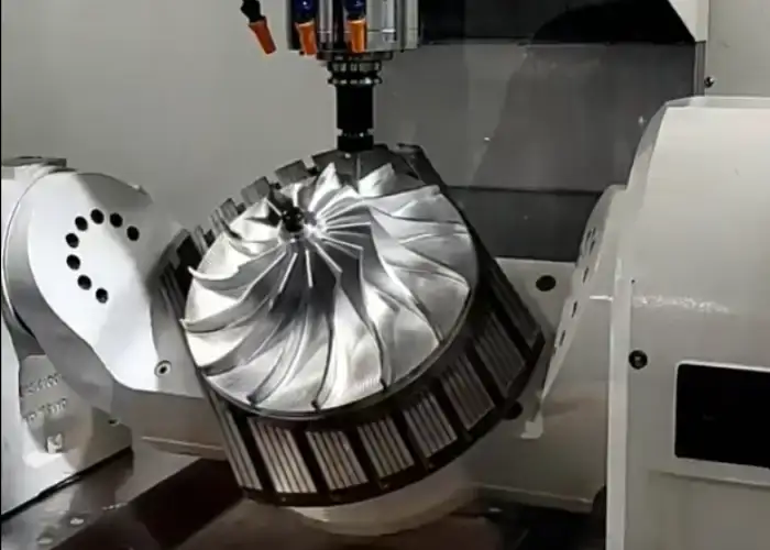
Roughing Toolpaths Between Blades
Roughing begins by defining the volume between adjacent blades.
The CAM system can use blade surfaces and root regions as drive or boundary surfaces so material is removed without cutting into the final geometry.
Hawk Ridge demonstrates a flowline-between-surfaces strategy for turbo impeller roughing, with upper and lower surfaces defining the machining region.
Blade Finishing Toolpaths
Blade finishing requires smooth, continuous motion along the curved surface.
The path should maintain consistent spacing so scallop height and surface texture remain predictable.
Abrupt direction changes should be minimized because they can create dwell marks or sudden cutting-load changes.
Tool Axis And Tilt Control
Five-axis programming allows the tool to tilt relative to the cutting direction.
The objective is to maintain good cutting contact while keeping the cutter and holder away from neighboring blades.
Hawk Ridge’s example uses explicit side-tilt control to orient the tool along blade walls rather than relying only on the cutter tip.
Gouge And Collision Checking
A mathematically valid toolpath can still be unsafe if the holder or tool body contacts another surface.
Gouge checking should therefore include nearby blades, the hub, holder clearance, and link moves between cutting passes.
Automatic tilt-away functions can help, but the resulting motion still needs to be reviewed for smoothness and machine-axis limits.
Toolpath Patterning Around The Impeller
Because blades repeat around the rotational axis, one verified machining region can often be patterned around the wheel.
This reduces programming repetition and helps keep each blade strategy consistent.
The pattern should reference the true impeller axis so angular spacing remains correct.
Machine Simulation And Post-Processor Verification
Toolpath simulation should include the actual machine configuration whenever possible.
Virtual machining helps identify rotary-axis limits, holder interference, table collisions, and unexpected retract moves before metal is cut.
Hawk Ridge specifically recommends running the generated code through a virtual five-axis machine to verify both toolpath safety and post-processor output.
How Are Cutting Tools Selected for Turbo Impeller Machining?
Tool selection depends on material, channel width, blade curvature, reach, surface requirements, and machining stage. Roughing favors rigidity and material removal, while finishing requires tools that can reach curved blade surfaces without excessive deflection or holder interference.
End Mills For Rough Machining
Rigid end mills or bull-nose cutters are effective for removing material between blades when channel access is sufficient.
Larger diameters improve stiffness and allow higher material removal rates.
The tool should still leave enough stock for semi-finishing and final surface generation.
Ball-Nose Tools For Curved Blade Surfaces
Ball-nose tools are useful for freeform blade surfaces because the rounded cutting edge can follow changing curvature.
They are especially helpful near blade roots and fillets where flat-end tools cannot maintain continuous contact.
Tool diameter should balance surface quality, accessibility, and rigidity.
Tool Length, Rigidity, And Holder Clearance
A tool must be long enough to reach the deepest region without the holder touching surrounding geometry.
However, excessive overhang reduces rigidity and increases vibration.
Five-axis tilt can often reduce the required extension by improving holder clearance.
Tool Wear And Replacement Control
Tool wear affects both surface texture and geometry.
As the cutting edge deteriorates, cutting forces rise and the blade may begin to show chatter, burrs, or dimensional drift.
For repeat production, planned tool-life limits are more reliable than waiting for visible tool failure.
What Are the Main Challenges In Turbo Impeller Machining?
The main difficulties in turbo impeller machining come from narrow flow channels, twisted blade surfaces, thin-section flexibility, long tool reach, continuous five-axis motion, and material-dependent tool wear. These factors interact, so improving one parameter without considering the others can simply move the problem elsewhere.
Narrow Channels And Limited Tool Access
As blade spacing decreases toward the hub, tool access becomes increasingly restricted.
Small cutters may fit the channel but lack the rigidity of larger tools.
The programmer must balance accessibility, effective cutter length, holder clearance, and acceptable cycle time.
Thin Blade Deflection And Vibration
A blade becomes less rigid as surrounding material is removed.
Finishing one side too aggressively can deflect the blade away from the cutter and produce profile error on the opposite side.
Balanced machining, light finishing cuts, sharp tools, and controlled engagement help reduce this effect.
Tool Interference And Collision Risk
The cutter, holder, spindle, and machine head may all approach neighboring blades during simultaneous motion.
Collision risk is therefore higher than in normal three-axis pocket milling.
CAM collision checking and full machine simulation are essential parts of the programming workflow rather than optional final checks.
Heat and Tool Wear In Difficult Materials
Titanium and nickel-based alloys generate more heat and tool stress than aluminum.
Excessive engagement can damage the cutter, increase blade deflection, and leave poor surfaces.
Cutting parameters, coolant delivery, tool coatings, and replacement intervals should match the material rather than using one universal impeller program.
Maintaining Consistent Blade Surface Quality
Surface quality must remain consistent from the first blade to the last.
Tool wear, machine temperature, changing engagement, and tool-axis motion can all create visible or measurable differences.
A stable production process controls these variables rather than relying on polishing to hide machining problems afterward.
How Are Blade Accuracy And Surface Finish Controlled?
Blade accuracy is controlled by maintaining stable datums, predictable stock allowance, rigid tooling, correct tool-axis orientation, and suitable finishing paths. Surface quality must be considered together with blade profile because aggressive polishing can improve appearance while changing the aerodynamic geometry.
Blade Profile Accuracy
Blade profile determines how closely the finished surface matches the CAD geometry.
CMM scanning, optical systems, or dedicated blade measurement methods may be used depending on size and specification.
Inspection should sample multiple blade locations rather than checking only one representative blade.
Leading And Trailing Edge Control
Leading and trailing edges are relatively thin and can be easily damaged during machining or manual finishing.
Excessive deburring may change the edge shape, while insufficient deburring can leave loose material.
These regions require controlled cutting and carefully defined edge treatment.
Blade Root And Fillet Accuracy
The root joins the blade to the hub and often experiences both geometric and structural importance.
Tool access becomes difficult as the channel narrows, making undercutting or residual stock possible.
Correct cutter size and smooth tool-axis control help maintain the designed fillet without gouging the hub.
Hub And Bore Concentricity
The hub and center bore establish the rotational reference of the impeller.
Poor concentricity can create radial runout even when blade geometry is correct.
Bore, hub, and blade pattern should therefore be inspected as related features rather than independent dimensions.
Surface Roughness And Tool Marks
Blade surfaces should be smooth enough to meet aerodynamic and drawing requirements.
Visible chatter, abrupt cusps, or deep cutter marks may indicate unstable cutting or unsuitable stepover.
Final surface requirements should come from the drawing,an unnecessarily low roughness specification can greatly increase cycle time.
What Impeller Balancing Methods Are Used?
Impeller balancing controls residual mass eccentricity after machining. Static balance can identify a heavy side in a single plane, while dynamic balancing evaluates rotating imbalance across multiple planes. High-speed turbo impellers generally require final balance verification because small mass differences can generate significant vibration at operating speed.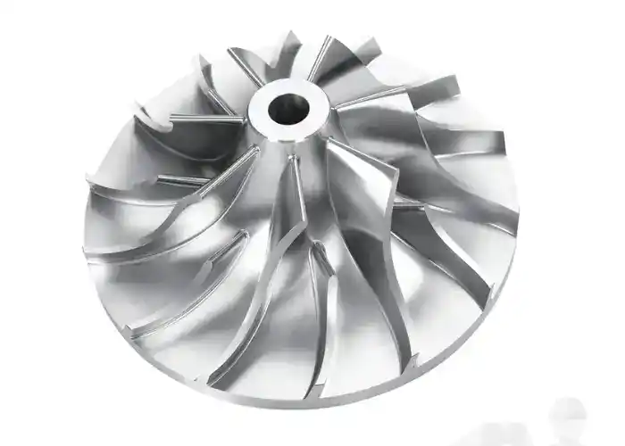
Why Balance Matters For Turbo Impellers
Imbalance creates centrifugal force as rotational speed increases.
This can increase vibration, bearing load, noise, and fatigue on the turbocharger assembly.
Good geometric machining reduces the amount of correction required, but machining accuracy alone does not replace balancing.
Static Vs Dynamic Balancing
Static balancing identifies whether the center of mass is offset from the rotational axis.
Dynamic balancing also considers how mass is distributed along the rotating component and detects coupled imbalance that may not appear during a simple static check.
The required method should follow the part specification and the way the impeller will operate in the final assembly.
How Balance Correction Is Performed
Correction normally removes or adjusts a controlled amount of material at an approved balancing location.
Material should not be removed randomly from functional blade surfaces because this can change aerodynamic geometry or weaken the component.
The drawing or balancing procedure should define permissible correction areas.
When Should Balancing Be Checked During Production?
Balancing is generally performed after the machining steps that determine final mass distribution.
If later coating, polishing, or assembly changes the mass significantly, balance may need to be verified again.
Ultirapid also places dynamic balance checking after machining and cleaning within its impeller inspection sequence.
How Is A Finished Turbo Impeller Inspected?
Final inspection should verify blade geometry, hub and bore relationships, runout, surface condition, material integrity, and residual balance. No single inspection method covers every risk, so dimensional measurement, surface inspection, and balancing should be matched to the drawing and application.
CMM And Blade Profile Inspection
CMM equipment can measure blade sections, hub geometry, bore location, and related datum features.
For complex freeform surfaces, multiple measured points or scanning methods provide a better picture than a few isolated dimensions.
The inspection datum should match the functional rotational reference.
Bore, Runout, And Concentricity Inspection
The center bore, shaft interface, and outside geometry should rotate around the intended axis.
Runout inspection helps detect errors that may come from bore position, setup error, distortion, or uneven finishing.
These conditions are directly related to balancing behavior.
Surface Roughness Inspection
Surface roughness should be measured where the drawing specifies it.
Visual inspection alone cannot confirm an Ra requirement.
Measurement direction and location should also remain consistent between first article and repeat production.
Material And Defect Inspection
Material certificates can confirm the specified alloy and condition.
For critical applications, additional non-destructive inspection may be specified to detect cracks or internal defects in the blank or finished part. Ultirapid includes defect inspection and material verification within its broader impeller quality process.
Final Dynamic Balance Verification
The final balance result confirms whether the completed impeller meets the required residual imbalance limit.
Balancing records should be associated with the correct part revision and production batch.
This is especially important when repeat orders must reproduce an already approved wheel.
What Common Defects Occur In Turbo Impeller Machining?
Common turbo impeller defects include blade profile error, chatter, excessive tool marks, root gouging, bore runout, and residual imbalance. Most of these problems are linked to process stability, tool access, cutter condition, or setup strategy rather than to one isolated CNC parameter.
Blade Profile Errors
Profile error may come from tool deflection, blade deflection, incorrect tool-axis control, or uneven stock allowance.
The risk increases in narrow channels where cutters become longer and smaller.
Semi-finishing and consistent finishing stock help reduce variation.
Chatter And Surface Tool Marks
Chatter creates repeating marks and may also introduce geometric error.
Common causes include excessive tool overhang, low blade rigidity, unstable cutting parameters, or worn tools.
The solution should address cutting stability instead of relying only on post-polishing.
Blade Root Gouging Or Undercutting
Gouging occurs when the tool or holder enters a surface that should remain untouched.
Blade roots are especially sensitive because several surfaces converge in a restricted area.
Accurate CAM boundaries, gouge checking, and suitable tool-axis control are required before running the program.
Bore And Runout Errors
Bore error may originate from poor datum transfer, workholding movement, thermal effects, or an unsuitable finishing operation.
Because the bore defines the rotation axis, small location errors can affect the entire impeller.
Critical bore finishing should therefore be planned as a functional operation.
Excessive Residual Imbalance
Residual imbalance can result from uneven blade machining, material variation, an off-center bore, or inconsistent manual finishing.
Balancing can correct a limited amount of mass error, but large corrections usually indicate that the machining process should be reviewed.
The best result comes from producing a geometrically and materially consistent wheel before balance correction begins.
How Do Machining Requirements Affect Cost And Lead Time?
Turbo impeller machining cost is driven by material, blade complexity, tool accessibility, tolerance, surface finish, five-axis machine time, tooling, balancing, and inspection. The most effective way to control cost is to define requirements around actual aerodynamic, assembly, and rotational functions rather than applying the tightest possible tolerance to every surface.
Material And Blank Condition
Billet machining may require significant material removal but offers flexibility for prototypes and design changes.
Forged or near-net-shape blanks can reduce cutting time but may require additional sourcing, tooling, or material verification.
Titanium and nickel alloys also increase tooling and machine time compared with aluminum.
Blade Geometry And Channel Accessibility
Complex blade curvature and narrow channels usually require smaller cutters, longer reach, and more five-axis motion.
This increases both programming and machining time.
A small design change that improves cutter access can sometimes reduce cost without changing functional blade geometry.
Tolerance And Surface Finish Requirements
Tight profile, bore, runout, and surface requirements add finishing and inspection operations.
Very fine surface finishes also require smaller stepovers, which increase the number of tool passes.
Specifications should distinguish aerodynamic surfaces and critical interfaces from nonfunctional areas.
Tooling And 5-Axis Machining Time
Five-axis machining reduces setups but uses higher-cost equipment and more complex CAM programming.
Special long-reach tools, tapered ball mills, and frequent tool replacement may further affect cost.
However, reducing manual repositioning and preserving datum relationships can make five-axis machining more economical than multiple simpler setups for complex turbo impellers.
Balancing And Inspection Requirements
Dynamic balancing, CMM inspection, surface roughness measurement, material certification, and NDT all add manufacturing time.
These controls should be included in the process plan from the beginning instead of being treated as optional work after machining.
Clear inspection requirements make quotation and production planning more reliable.
FAQs
Can A Turbo Impeller Be Machined On A 3-Axis CNC Machine?
Some simple hub or reference features can be produced on three-axis equipment, but complex turbo impeller blades usually require five-axis machining for practical access. Simultaneous tool-axis control allows the cutter to follow twisted blade surfaces while avoiding adjacent blades and the tool holder.
Which Material Is Best For A Machined Turbo Impeller?
There is no single best material. Aluminum is attractive for lightweight compressor wheels and good machinability, while titanium provides higher strength-to-weight capability in demanding applications. Nickel-based alloys may be selected when temperature resistance is more important. The operating conditions should determine the material before machining cost is considered.
How Can Blade Deflection Be Reduced During Machining?
Blade deflection can be reduced by maintaining uniform finishing allowance, using rigid and sharp tools, limiting cutting forces, selecting suitable tool orientation, and avoiding aggressive finishing cuts on thin sections. The machining sequence should also preserve blade support for as long as practical before final finishing.
Is Dynamic Balancing Required After CNC Machining?
For high-speed turbo impellers, balance verification is normally an important final quality step when required by the design specification. CNC machining can produce good rotational symmetry, but material variation, bore error, blade variation, and secondary finishing can still create residual imbalance that requires measurement and correction.
Conclusion
Turbo impeller machining requires more than generating complex blade surfaces on a five-axis machine. Blade geometry, tool access, material behavior, stock allowance, tool-axis control, bore concentricity, surface finish, and mass distribution all influence final performance. A reliable process connects CAD review, CAM simulation, stable roughing, controlled blade finishing, dimensional inspection, and balancing so that aerodynamic geometry and rotational quality are maintained together.
At TiRapid, we provide precision CNC machining and manufacturing services for complex impellers and high-performance rotating components. Our capabilities include multi-axis machining, engineering material support, DFM, dimensional inspection, surface finishing coordination, and controlled repeat production to help customers achieve consistent blade geometry, reliable quality, and efficient project delivery.