
CNC turning surface finish directly affects component assembly accuracy, wear resistance, sealing performance, and service life. For companies purchasing precision shafts, metal sleeves, threaded connectors, and custom turned components, meeting dimensional specifications is not always enough. Visible tool marks, burrs, chatter marks, or localized scratches can also affect assembly and product performance. Achieving a consistent surface finish requires the right combination of cutting tool material, tool nose radius, cutting speed, feed rate, coolant delivery, and machine rigidity. By optimizing machining parameters and inspection procedures, manufacturers can reduce rework, improve the consistency of CNC turned parts, and control overall production costs.
What Is CNC Turning Surface Roughness? How Does the Ra Value Affect Part Quality?
CNC turning surface roughness measures the microscopic irregularities on a machined surface. It is commonly expressed as Ra, or the arithmetic average roughness. A lower Ra value generally indicates a smoother surface profile. However, determining whether a component meets its functional requirements also requires consideration of waviness, burrs, scratches, roundness, and other geometric characteristics.
In precision manufacturing, different components require different surface finishes. General connectors may only need standard machining quality, while bearing seats, sliding contact surfaces, sealing areas, and precision transmission components often require tighter surface control. When preparing engineering drawings, purchasing teams should specify surface roughness according to the actual function of each component rather than automatically requesting the lowest possible Ra value.
Common CNC Turning Ra Values and Their Applications
The following values illustrate typical surface finish requirements. Actual specifications should be determined according to material, machining process, and component function.
| Surface Roughness | Typical Surface Characteristics | Common Applications |
| Ra 6.3 μm | Noticeable machining marks | Non-critical surfaces and general mechanical parts |
| Ra 3.2 μm | Standard turned finish | General shafts and connectors |
| Ra 1.6 μm | Finer machined surface | Precision mechanical parts and mating surfaces |
| Ra 0.8 μm | Relatively smooth surface | Components requiring improved contact quality |
| Ra 0.4 μm or lower | Fine surface finish | Selected precision fits and functional surfaces |
These values are not guaranteed results for every material or machine. The final finish depends on tool geometry, cutting conditions, material adhesion, machine vibration, and measurement methods. For components with strict technical requirements, engineering drawings should clearly specify the roughness standard and inspection locations.
Why Does Surface Roughness Affect Component Performance?
- Assembly accuracy: If a shaft interfaces with a bearing or a sleeve fits over a pin, excessive surface irregularities may affect actual contact conditions and assembly clearance.
- Wear resistance: Surface conditions influence friction, lubricant film formation, and wear behavior. Actual performance also depends on material, load, and lubrication.
- Sealing reliability: Scratches or unsuitable surface patterns on sealing interfaces can increase the risk of leakage.
- Fatigue performance: Certain components exposed to cyclic loading are sensitive to surface notches and machining defects, making surface quality particularly important.
- Appearance quality: Consistent surface textures improve the visual appearance of exposed metal components and support more uniform surface finishing.
Understanding the practical significance of Ra specifications helps engineering teams establish appropriate machining standards while balancing surface quality, manufacturing efficiency, and purchasing costs.
How to Select CNC Turning Tools for Better Surface Finish
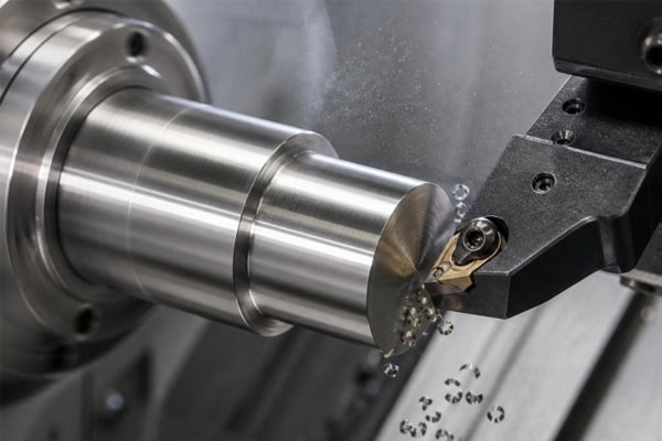
Tool geometry, insert material, cutting-edge condition, and tool wear all influence how material is removed and how the final surface appears. Even when the same CNC lathe is used, unsuitable inserts, worn cutting edges, or built-up edges can produce noticeable machining marks. For precision CNC turning projects, tool selection should account for workpiece material, cutting conditions, component geometry, and the required surface finish.
Tool Selection Tips for Different Workpiece Materials
Selecting an insert designed for the workpiece material can reduce cutting resistance, improve chip formation, and minimize surface defects.
- Aluminum turning: Aluminum alloys generally offer good machinability, but some grades are prone to built-up edges and material adhesion. Sharp, polished inserts designed for aluminum can improve surface finish when the cutting edge is kept clean.
- Stainless steel turning: Stainless steel can generate significant cutting heat and undergo work hardening. Inserts need suitable toughness, wear resistance, and chip-control characteristics. Avoid prolonged rubbing between the tool and workpiece.
- Carbon steel and alloy steel turning: Select insert grades according to material hardness and heat-treatment condition. For finishing operations, cutting-edge sharpness, insert stability, and wear control are particularly important.
- Brass turning: Brass generally offers good machinability. Suitable tool geometry can help reduce burrs and edge defects.
- Engineering plastic turning: Materials such as POM and PEEK require careful control of cutting heat, elastic deformation, and clamping pressure. Sharp tools and appropriate cutting parameters help minimize burrs, melting marks, and dimensional changes.
Materials, tools, and cutting parameters must work together. For difficult-to-machine materials or high-precision components, trial cuts and surface measurements should be used to establish the final process rather than copying parameters from an unrelated material.
How Do Tool Nose Radius and Cutting-Edge Condition Affect Ra?
The tool nose radius influences the theoretical residual height of turning marks. Under otherwise similar conditions, a suitable increase in nose radius can reduce geometric surface roughness. However, an excessively large radius may increase radial cutting forces, making slender shafts, thin-walled components, or parts with insufficient rigidity more susceptible to vibration.
During machining, consider the following practices:
- Select a suitable nose radius according to component rigidity to prevent excessive cutting forces from generating chatter marks.
- Use inserts in good condition for finishing operations, replacing tools that show significant wear, chipping, or material adhesion.
- Check toolholder overhang and insert clamping to minimize elastic deformation within the tooling system.
- Use appropriate workholding and support for thin-walled components to reduce deformation-related surface defects.
- Choose chipbreaker geometry suitable for the workpiece material to prevent chips from scratching the finished surface.
Appropriate tooling improves surface finish and helps maintain dimensional stability during batch production, reducing quality variations caused by changes in tool condition.
How to Adjust CNC Turning Cutting Parameters to Reduce Surface Roughness
Cutting speed, feed rate, and depth of cut are key parameters affecting CNC turning surface quality. The optimal settings vary according to material, tooling, and machine rigidity. Increasing spindle speed alone does not guarantee a better finish if feed rate, tool geometry, and workpiece support are not properly controlled.
A more reliable approach is to optimize the finishing operation using tool manufacturer recommendations, material properties, and trial-cut results.
Optimizing Feed Rate and Cutting Speed
Under a simplified ideal geometric model, theoretical turning roughness is related to the square of the feed per revolution and inversely related to the tool nose radius. A commonly used approximation is:
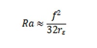
Where:
(f) represents feed per revolution.
(r_\varepsilon) represents the tool nose radius.
This formula helps explain the influence of geometric tool marks. It does not guarantee the actual Ra value because vibration, tool wear, material adhesion, and machine errors can affect the final surface.
Practical parameter optimization methods include:
- Reduce finishing feed rate appropriately: A lower feed rate generally reduces theoretical tool-mark height. However, excessively low feed rates may cause rubbing, material adhesion, or reduced productivity. Trial cuts help establish a suitable range.
- Optimize cutting speed: For certain materials, increasing cutting speed can reduce built-up edges and improve surface quality. However, insert heat resistance, machine speed limits, and cutting temperature must be considered.
- Maintain consistent finishing allowance: Excessive stock can increase cutting loads, while insufficient stock may cause the tool to rub the surface without maintaining stable cutting conditions.
- Separate roughing and finishing parameters: Roughing prioritizes stable material removal, while finishing focuses on surface quality, dimensional accuracy, and cutting stability.
- Verify results through trial cuts: Measure the actual surface with a roughness tester and record the parameters, tool condition, and material batch to establish a repeatable production window.
How to Coordinate Depth of Cut and Machining Allowance
Depth of cut influences cutting forces, heat generation, and tool loading. Roughing operations typically prioritize material removal rates, while finishing operations require a consistent and appropriate machining allowance to prevent sudden variations in cutting load.
For slender shafts, thin-walled sleeves, and small-diameter components, excessive depth of cut can cause workpiece deflection or vibration. Adjust the machining sequence according to the component structure, use suitable clamping and support methods, and avoid sudden changes in cutting load during finishing.
For stepped shafts with multiple diameters, tool paths should also be planned carefully to minimize surface marks caused by tool entry and exit.
How to Optimize CNC Turning Coolant and Chip Removal to Prevent Scratches and Chatter
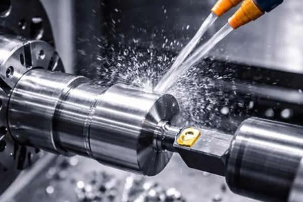
Coolant, cooling methods, and chip evacuation affect both tool life and workpiece surface quality. If chips cannot leave the cutting zone efficiently, they may repeatedly rub against the tool and workpiece, producing scratches, indentations, or localized roughness variations. Effective chip management is particularly important when turning stainless steel, deep-bore sleeves, and shaft components in continuous production.
Coolant Delivery and Cutting Zone Management
- Ensure coolant reaches the cutting zone: Nozzle positioning and flow direction should match the tool feed direction to provide effective coverage of the cutting area.
- Maintain coolant condition: Manage concentration, cleanliness, and filtration according to machine and material requirements to prevent contaminants from scratching the workpiece.
- Choose an appropriate lubrication method: Different materials require different cooling and lubrication conditions. Follow suitable tooling recommendations and equipment capabilities.
- Control heat accumulation: During continuous production, monitor workpiece temperature and machine thermal conditions to reduce dimensional and surface variations.
- Avoid unsuitable intermittent cooling: Under certain tooling and cutting conditions, inconsistent coolant delivery can cause thermal shock. Cooling practices should match the tool material and machining process.
Chip Control and Vibration Management
Chip evacuation and machine rigidity should be optimized together, particularly when machining deep bores, slender shafts, or materials that produce long, continuous chips.
- Select suitable chipbreaker geometry and feed parameters to produce chips that can be evacuated efficiently.
- Check tool overhang to reduce vibration caused by excessive toolholder extension.
- Use a tailstock, steady rest, or other suitable support for slender shafts.
- Inspect collets, chucks, soft jaws, and locating surfaces to ensure stable workholding and minimize eccentricity.
- Monitor abnormal vibration in the spindle, tool turret, and workholding system, and inspect for wear or looseness.
- Remove chips promptly after machining to prevent scratches during handling and storage.
When cutting parameters, coolant delivery, and chip evacuation are properly controlled, surface quality becomes easier to maintain consistently during continuous production.
How to Inspect CNC Turned Surface Roughness and Maintain Batch Consistency
Visual inspection can identify obvious scratches, burrs, and irregular tool marks, but it cannot replace professional roughness measurement. Precision components with specified Ra requirements should be measured using a suitable surface roughness tester, following the required measurement locations, direction, and applicable standards.
For high-precision components or critical functional surfaces, surface roughness inspection should be combined with dimensional measurements, roundness checks, runout measurements, and other geometric inspections.
Practical Quality Inspection Methods for CNC Turning
- First-article inspection: When introducing a new program, tool, or material batch, inspect critical dimensions and surface finish to verify that the process meets drawing requirements.
- In-process inspection: Establish sampling frequency according to production volume, component risk, and tool wear to detect changes in machining conditions early.
- Final inspection: Confirm critical dimensions, roughness, thread specifications, and appearance before delivery.
- Tool life management: Record tool operating time, production quantity, and surface measurement results to schedule tool changes before quality deteriorates.
- Inspection record management: Retain measurement results and machining parameters for important components to trace batch variations and support continuous improvement.
Companies purchasing CNC turning services should clearly specify surface roughness requirements and the applicable surfaces on their engineering drawings. If only certain mating surfaces require a low Ra value, those locations should be identified explicitly to avoid unnecessary finishing operations across the entire component.
How to Choose a Precision CNC Turning Supplier
Supplier selection is equally important for achieving consistent surface finish and dimensional accuracy. In addition to machine configuration, buyers should evaluate engineering review capabilities, material availability, tooling management, inspection equipment, surface treatment support, and batch quality control procedures.
TiRapid provides CNC turning, CNC milling, and other precision manufacturing services for companies requiring custom metal components, engineering plastic parts, prototypes, and production batches.
When requesting a quotation, provide STEP or STP 3D CAD models, 2D engineering drawings, material grades, quantities, target Ra values, and critical tolerances. These details help the engineering team assess manufacturability and prepare an appropriate quotation.
When evaluating a supplier, consider the following:
- Can the supplier machine the specified materials and meet critical drawing tolerances?
- Does the supplier have suitable surface roughness and dimensional inspection equipment?
- Can the supplier provide first-article approval and in-process inspection?
- Can the supplier offer Design for Manufacturability (DFM) recommendations based on component geometry?
- Does the supplier have sufficient production capacity and a suitable delivery schedule?
- Can the supplier meet deburring, surface treatment, and packaging requirements?
By defining surface roughness requirements, selecting appropriate cutting tools, optimizing cutting parameters, controlling coolant and chip evacuation, and implementing a consistent inspection process, manufacturers can improve CNC turning surface quality and batch consistency.
For projects involving precision shafts, sleeves, threaded components, and custom rotational parts, specify material, dimensions, tolerances, and surface finish requirements during the quotation stage to obtain a manufacturing solution that matches the actual application.
















