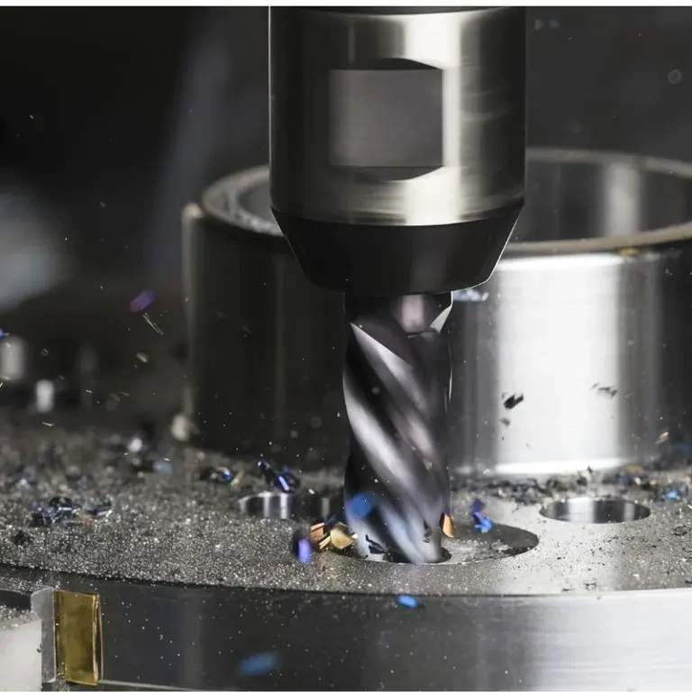
CNC turning surface roughness is one of the most important quality indicators in precision machining. For shafts, sleeves, connectors, threaded components, valve parts, and high-precision rotating components, meeting dimensional requirements alone does not necessarily mean the machining process is complete. Surface roughness, machining marks, burrs, and localized defects can also affect assembly and functional performance. Different materials, cutting tools, tool nose radii, spindle speeds, feed rates, cutting depths, and cooling conditions can all influence the final surface finish. When sourcing CNC turning services, manufacturers should define the required Ra value according to the intended application and use a controlled machining process to maintain consistent surface quality across production batches.
Why Does Surface Roughness Matter in CNC Turning?
Surface roughness is more than an appearance-related specification. For components that require mating, sealing, sliding, or high-speed rotation, the microscopic surface profile can affect friction, wear, sealing performance, and assembly conditions. For example, when a shaft interfaces with a bearing or a piston rod works with a sealing component, excessive roughness may increase friction and wear. An unstable surface condition can also reduce sealing performance or create abnormal assembly resistance. CNC turning processes should therefore establish an appropriate surface roughness target according to the component’s actual application instead of simply pursuing the lowest possible Ra value.
Different Applications Require Different Ra Values
Different components operate under different conditions, so their surface roughness requirements can vary considerably. General structural parts may only require standard machining quality, while high-speed shafts, sealing surfaces, and precision sliding components often require tighter surface control.
- General external turning: Focus on dimensional stability and uniform machining marks
- Precision shafts: Control diameter tolerance, roundness, and surface roughness together
- Sealing surfaces: Control surface texture and microscopic defects
- Sliding surfaces: Reduce friction and abnormal wear
- Threaded mating surfaces: Maintain stable thread profiles and surface quality
- High-speed rotating components: Control surface finish and runout together
Setting a reasonable Ra target helps prevent a mismatch between machining capability and product requirements while avoiding unnecessary finishing costs.
Surface Roughness Can Affect Assembly
Precision components often need to be assembled with other parts. Even when dimensional inspection is satisfactory, obvious tool marks, burrs, or localized scratches can make assembly difficult. For shafts, bushings, positioning pins, and precision turned components, a stable surface condition helps improve assembly consistency and reduce rework and manual finishing.
During CNC turning, dimensional accuracy and surface quality should be controlled together. Coordinating tool selection, cutting parameters, and coolant conditions can help achieve the requirements specified on the engineering drawing.
Which CNC Turning Parameters Affect Surface Roughness?
Turning surface quality is closely related to cutting parameters. Many machining defects are not caused by insufficient machine accuracy but by an improper combination of cutting speed, feed rate, cutting depth, and tool condition. Even when the same material, machine, and tool are used, changes in machining parameters can significantly affect the final Ra value and machining pattern.
Feed Rate Directly Affects Machining Marks
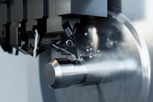
Feed rate is one of the key parameters affecting turned surface roughness. A higher feed rate generally creates more pronounced theoretical machining marks on the workpiece surface, while reducing the feed rate can improve surface finish at the cost of longer machining time. Actual production parameters should be selected according to tool nose radius, material, machining stage, and dimensional requirements.
- Use higher feed rates for efficient roughing
- Use controlled feed rates during semi-finishing
- Optimize feed rate carefully during finishing
- Lower feed rates can produce finer machining patterns
- Excessively low feed rates may increase machining time
- Consider tool life and production efficiency together
Proper feed-rate control helps establish a practical balance between machining efficiency and surface quality.
Cutting Speed Affects Temperature and Tool Condition
Spindle speed and cutting speed influence cutting-zone temperature, tool wear, and machining stability. Aluminum alloys and brass can often be processed at relatively high cutting speeds when supported by suitable tooling and machine capabilities. Stainless steel and titanium alloys generally require more careful control of heat generation and tool load.
When cutting speed is unsuitable, problems such as built-up edge, rapid tool wear, surface tearing, or irregular machining marks may occur. During finishing operations, maintaining a stable cutting edge is particularly important for minimizing surface-quality variations between production batches.
Cutting Depth Influences Machining Stability
Cutting depth primarily affects material removal and cutting load. Roughing operations can use larger cutting depths to remove excess material efficiently, while finishing operations generally require an appropriate finishing allowance so the tool can produce the final surface consistently.
If the finishing allowance is too small, the tool may rub against the surface instead of cutting effectively. If the allowance is excessive, cutting forces may increase and affect surface quality. The machining program should establish appropriate roughing, semi-finishing, and finishing allowances according to the raw material dimensions and part geometry.
How Can Tool Selection Reduce CNC Turning Surface Roughness?
The cutting tool directly contacts the workpiece, so its edge condition, nose radius, tool material, and geometry all influence the final surface finish. For precision CNC turning projects, tool selection should not focus only on whether the tool can remove material. Long-term stability during continuous production is equally important.
Select an Appropriate Tool Nose Radius
Tool nose radius affects the theoretical machining pattern. A suitable nose radius can improve surface finish and strengthen the cutting edge. However, a larger nose radius is not always better. When machining thin-wall parts, slender shafts, or components with limited rigidity, an excessively large nose radius can increase radial cutting forces and lead to vibration.
- Select the nose radius according to the turning operation
- Match finishing tools to the target Ra value
- Reduce deformation and vibration risks when machining thin-wall parts
- Consider tool rigidity for slender shafts
- Check tool accessibility for small precision components
- Avoid interference when machining complex profiles
The tool nose radius should be properly matched with the feed rate and other cutting parameters to achieve stable surface quality.
Select Cutting Inserts According to the Material
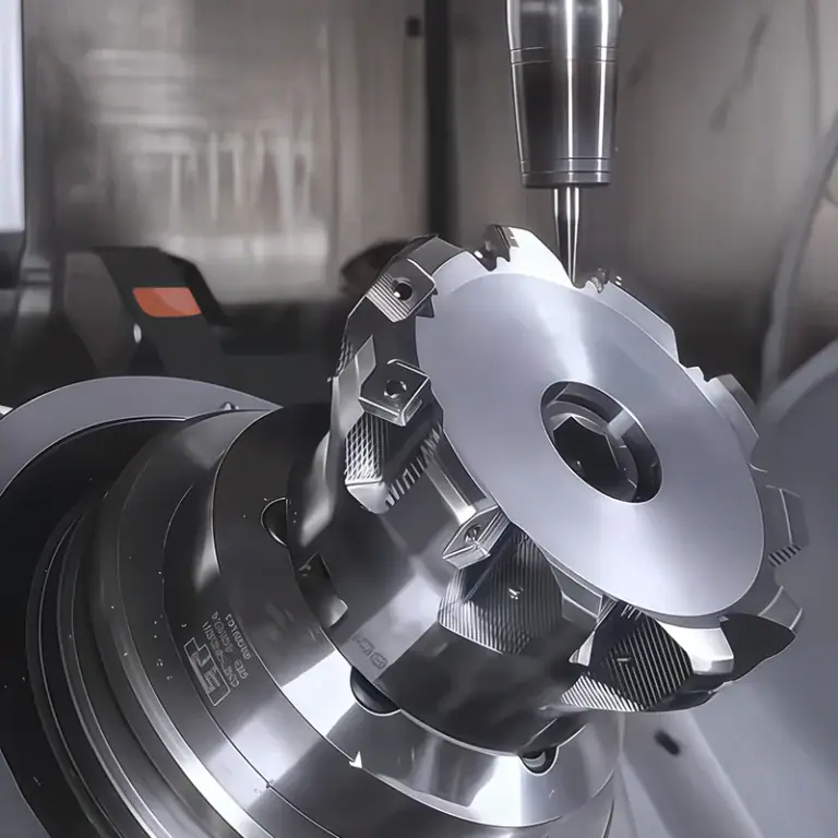
Different materials require different insert materials and coatings. Aluminum alloys generally benefit from sharp cutting edges and efficient chip evacuation. Stainless steel requires a balance of toughness, wear resistance, and thermal performance. Harder materials may require carbide or other specialized tooling based on actual machining conditions.
Stable tool condition helps minimize variations in tool marks and surface defects. During high-volume production, manufacturers should also establish tool-life management procedures and replace tools at appropriate wear limits to prevent noticeable differences in surface quality between parts.
How Do Workholding and Machine Rigidity Affect Surface Quality?
Even with appropriate tooling and cutting parameters, unstable workholding or insufficient machine rigidity can generate significant vibration. Cutting vibration may create periodic patterns on the workpiece surface and, in severe cases, cause dimensional variation, tool chipping, and localized machining defects. This issue is particularly important when machining slender shafts, thin-wall sleeves, and components with long tool or workpiece overhangs.
Optimize Workholding to Reduce Vibration
The workholding method should be selected according to the part length, diameter, material, and structural characteristics. For long shafts, tailstocks, steady rests, or follower rests can provide additional support during machining. For thin-wall components, clamping force should be carefully controlled to prevent deformation.
- Minimize tool overhang
- Increase workpiece clamping rigidity
- Use tailstock support when appropriate
- Add support for long-shaft machining
- Control clamping pressure for thin-wall parts
- Check chuck clamping conditions
- Reduce errors caused by repeated workholding
Stable workholding provides a reliable foundation for precision finishing and helps reduce vibration-related surface defects.
Machine Condition Also Requires Regular Inspection
Spindle runout, guideway condition, turret positioning accuracy, and fixture wear can all affect machining results. If machine accuracy gradually deteriorates after long-term operation, surface quality may decline even when the machining program remains unchanged.
For batch CNC turning production, manufacturers should establish regular machine inspection and maintenance procedures. First-piece inspection and in-process inspection can also help identify changes in machining conditions before they affect a large number of components.
How Can Precision CNC Turning Achieve Stable Ra Control?
Stable surface roughness control requires coordinated management of process planning, tooling, machine condition, cooling, and inspection. For precision components supplied over long production cycles, achieving the target Ra value on one trial part is not enough. Subsequent production batches must also maintain consistent machining conditions.
Establish a Controlled Roughing-to-Finishing Process
A properly planned machining sequence reduces the workload placed on the finishing operation. Roughing is mainly used to remove material efficiently, semi-finishing corrects the profile and dimensions, and finishing establishes the final dimensions and surface quality. For high-precision components, additional finishing operations may be introduced according to the material and part geometry.
- Remove excess material efficiently during roughing
- Correct the profile during semi-finishing
- Control final dimensions during finishing
- Adjust cutting parameters according to material
- Select finishing tools based on the required Ra value
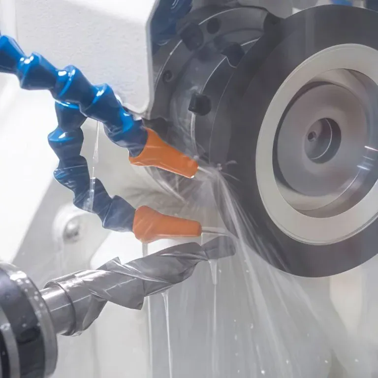
- Use coolant to control cutting temperature
- Inspect critical surfaces carefully
A standardized machining process reduces variations caused by manual adjustments and helps maintain consistent quality between production batches.
Use Professional Equipment to Verify Surface Roughness
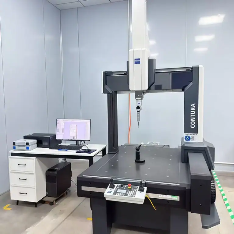
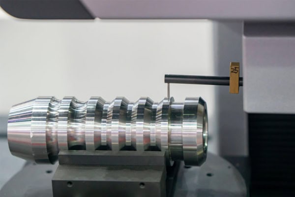
Surface roughness should not be judged solely by visual inspection. When a specific Ra requirement is defined on an engineering drawing, professional surface roughness measurement equipment should be used to verify the result at the specified inspection locations.
Inspection should not focus only on a single component. Changes between production batches and different stages of machine operation should also be monitored. If the Ra value gradually increases, possible causes may include tool wear, changes in cutting parameters, or machine-condition issues.
Inspection data can be used to adjust tooling and machining parameters in time, reducing the risk of surface-quality inconsistencies during batch production.
How to Choose a CNC Turning Manufacturer for Precision Components?
When components require controlled surface roughness, tight dimensional tolerances, and stable batch production, the supplier’s process capability can directly influence the final quality. When sourcing CNC turning services, buyers should consider more than price. Machine capability, material experience, inspection equipment, engineering communication, and production consistency are all important considerations.
Prepare Complete Part Information Before Sourcing
Clear engineering drawings help the machining supplier understand the component requirements accurately. For parts with specific Ra requirements, critical surfaces should have clearly defined surface roughness specifications. Material, dimensions, tolerances, quantities, and special processing requirements should also be provided.
- 2D engineering drawings
- 3D CAD models
- Material grade
- Critical dimensional tolerances
- Surface roughness requirements
- Production quantity
- Surface finishing requirements
- Quality inspection requirements
More complete information allows the engineering team to evaluate machining feasibility, tooling configuration, and production planning more efficiently and helps generate a more accurate quotation.
Validate Batch Machining Capability With Samples
For precision components, sample validation allows buyers to confirm dimensions, surface finish, and assembly conditions before moving into volume production. Critical dimensions and key surfaces can be inspected during sample production to verify that the proposed process meets design requirements.
For components requiring long-term supply, buyers can also request relevant inspection records to establish a clearer quality-control reference for subsequent production batches.
TiRapid provides CNC turning, precision CNC machining, and manufacturing services from prototyping to production. Based on engineering drawings, material specifications, dimensional tolerances, and surface finishing requirements, its engineering team can develop an appropriate machining solution. For projects with defined Ra values, dimensional tolerances, and batch delivery requirements, providing complete engineering information during the quotation stage helps the engineering team evaluate machining feasibility and production requirements.
Through appropriate tool selection, cutting parameters, workholding methods, coolant systems, and inspection procedures, manufacturers can effectively improve the surface quality of CNC-turned components. For precision shafts, sleeves, connectors, and other rotational components, clearly defining the required Ra value and continuously monitoring the machining process is more practical than simply pursuing the lowest possible roughness value. Stable process control helps maintain an appropriate balance between dimensional accuracy, surface finish, and batch consistency while reducing rework risks and improving long-term supply reliability.