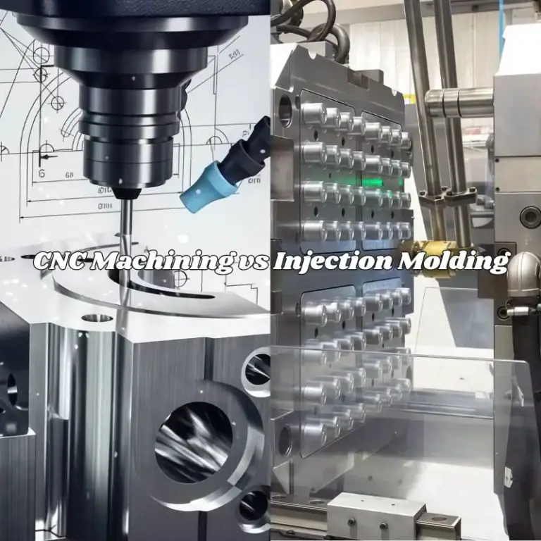
Long shaft components are widely used in industrial robots, automated production lines, automotive transmission systems, hydraulic equipment, and precision rotating mechanisms. As equipment requirements for rotational accuracy, operating stability, and assembly performance continue to increase, CNC turning of long shafts requires more than meeting the diameter and length dimensions specified in engineering drawings. Radial runout, roundness, straightness, and positional relationships between different shaft journals must also be controlled. For slender shafts, drive shafts, precision guide shafts, and long rotational components, increasing part length can make bending, vibration, and thermal deformation more noticeable, potentially causing dimensional deviations, surface chatter marks, and assembly problems. Proper CNC turning process design, suitable workpiece support, and an effective precision inspection procedure can improve long-shaft machining stability and reduce quality risks during batch production. Understanding the machining challenges, precision control methods, and supplier evaluation requirements helps manufacturers source custom shaft components that meet their technical specifications.
Why Does CNC Turning of Long Shafts Easily Cause Runout and Dimensional Deviations?
Long shaft components typically have a high length-to-diameter ratio, making them more susceptible to radial cutting forces and the effects of their own weight during turning. Compared with short shafts or highly rigid rotational components, slender shafts have lower bending stiffness. Workholding positions, support spacing, and cutting forces can all affect machining accuracy. When a shaft requires multiple journals, steps, grooves, and threaded sections, positioning errors between different operations can accumulate and cause excessive runout or positional deviations between shaft sections. A suitable process must consider workpiece rigidity, cutting forces, and machine conditions.
Insufficient Workpiece Rigidity Can Cause Shaft Bending
During turning, slender shafts may elastically bend under radial cutting forces. If the unsupported length is excessive or the support point is too far from the cutting area, cutting forces can cause significant deflection. After machining and unloading, elastic recovery may lead to changes in outside diameter, shaft-axis bending, and increased radial runout. This is particularly important for long transmission shafts, precision guide shafts, and small-diameter shaft components.
- Control workpiece overhang: Arrange the clamping position according to shaft diameter, material rigidity, and machining length to minimize unnecessary overhang and reduce bending during cutting.
- Choose an appropriate support method: Depending on part length, diameter, and machining stage, use a tailstock center, steady rest, or follower rest to improve slender-shaft rigidity.
- Optimize the cutting direction: Plan machining operations according to workholding and support conditions to reduce excessive radial loads in weaker sections.
- Control machining allowance: Remove material in stages instead of applying excessive cutting loads in a single operation, reducing the risk of bending and local dimensional deviations.
Improving workpiece support and controlling cutting loads helps reduce bending during long-shaft machining and improves the stability of journal dimensions and shaft-axis positioning.
Cutting Vibration Can Cause Chatter Marks and Radial Runout
During long-shaft turning, the workpiece, fixture, cutting tool, and machine spindle form a dynamic system that can influence one another. When system rigidity is insufficient or cutting parameters are poorly matched, vibration and chatter may occur. Vibration can leave periodic marks on the shaft surface and cause the actual cutting depth to fluctuate, resulting in outside-diameter variations, increased surface roughness, and reduced dimensional consistency. For high-speed rotating shafts, precision transmission shafts, and bearing-fit components, controlling surface quality and runout is particularly important.
- Optimize spindle speed: Select a stable speed range according to workpiece length, diameter, support conditions, and tool condition to avoid unstable cutting speeds.
- Improve tool system rigidity: Select appropriate tool-holder dimensions, tool overhang, and cutting-edge geometry to reduce vibration caused by excessive tool extension.
- Control tool wear: Inspect insert edges regularly and avoid increased cutting forces caused by dulling, chipping, or built-up material.
- Improve workpiece support:Adjust steady-rest or follower-rest conditions according to the actual cutting position to reduce vibration and local deflection.
Effective vibration control produces more uniform surface patterns, reduces dimensional fluctuations, and improves the rotational stability and assembly reliability of long shaft components.
Multiple Workholding Operations Can Cause Journal Positioning Errors
Long shafts often contain multiple stepped sections, bearing seats, keyway areas, threaded sections, and precision journals. If different shaft sections require repeated workholding operations, every repositioning may introduce a datum shift, causing the centerlines of different journals to deviate from one another. For transmission shafts supported by multiple bearings or used in high-speed rotation, radial runout and positional accuracy between journals directly affect operating performance. An unsuitable machining datum can also result in individual dimensions being acceptable while the overall rotational accuracy remains outside the required range.
- Use consistent machining datums: Establish stable axial and radial positioning datums based on the drawing and functional requirements to reduce datum changes between operations.
- Minimize repeated workholding: When machine capabilities permit, complete multiple journals and stepped sections in one setup to reduce repeated positioning errors.
- Control center-hole quality: For shafts machined between centers, ensure that center-hole position, geometry, and contact conditions meet process requirements.
- Inspect relationships between critical shaft sections: Measure multiple journals according to the drawing datum rather than judging the entire shaft based only on individual outside-diameter measurements.
Proper datum selection and workholding planning help reduce positional errors between shaft sections and improve the overall machining accuracy of long shafts.
How Can Precision CNC Turning Processes Improve Long-Shaft Machining Stability?
Precision long-shaft machining requires coordinated control of workholding, tooling, cutting parameters, and operation sequencing. Different materials and geometries require different process strategies. Aluminum long shafts require attention to thermal expansion and rigidity, while stainless steel and alloy steel shafts require careful management of cutting forces, tool wear, and work hardening. For high-precision transmission shafts, guide shafts, and rotational components, an appropriate process route can reduce machining deformation, improve surface quality, and provide a reliable foundation for subsequent grinding, heat treatment, or assembly operations.
Use Steady Rests and Follower Rests to Improve Long-Shaft Support
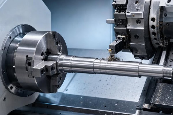
Auxiliary support is a common process method for CNC turning of slender shafts. A tailstock center provides support at the free end of the workpiece, a steady rest supports the shaft at a specified position, and a follower rest provides support close to the cutting area to reduce workpiece deflection caused by cutting forces. Different support methods are suitable for different geometries and should be selected according to machining length, shaft diameter, cutting position, and surface requirements.
- Tailstock center support: Suitable for long shafts with center holes, improving workholding stability and reducing vibration at the free end.
- Steady rest support: Suitable for long components where intermediate support is required to reduce bending in extended unsupported sections.
- Follower rest support: Suitable for certain slender-shaft external turning applications where support close to the cutting tool helps reduce local deformation.
- Optimize support positions: Support positions should provide sufficient rigidity while maintaining tool access and protecting the workpiece surface.
More support is not necessarily better. Support force and position should be adjusted according to actual workpiece conditions. Proper support improves machining stability while preventing new dimensional errors caused by excessive or poorly positioned support.
Optimize Roughing, Semi-Finishing, and Finishing Operations
Long-shaft machining generally requires multiple stages for material removal and dimensional control. Roughing removes the majority of excess material, semi-finishing corrects the profile and establishes consistent finishing allowance, while finishing produces the final dimensions and surface quality. For components affected by heat treatment or residual stress, appropriate stabilization or intermediate processes may need to be evaluated according to material condition and drawing requirements. Proper sequencing reduces the influence of material-removal stress changes on shaft straightness and runout.
- Roughing: Remove the majority of material while the workpiece still has relatively high rigidity, controlling cutting forces and avoiding excessive local material removal.
- Semi-finishing: Correct shaft profiles, establish consistent finishing allowances, and inspect the workpiece for significant bending or dimensional changes.
- Finishing: Complete critical journals, mating sections, and end faces under stable workholding and support conditions, with close control of dimensions and surface quality.
- In-process inspection:Check outside diameters, relevant straightness requirements, and runout trends during critical machining stages to prevent defects from accumulating into the final operation.
Staged machining reduces the cutting load in individual operations, allowing long shafts to gradually reach their final dimensions while improving consistency between different shaft sections.
Select Cutting Parameters According to Material and Part Geometry
Long-shaft cutting parameters should consider material grade, workpiece diameter, length, support method, tool performance, and machine rigidity. Excessive cutting speed may increase vibration and thermal variation, while excessive feed rates can increase radial cutting loads. Improper cutting depth may also cause local deformation. For precision long shafts, parameter optimization should not focus solely on reducing machining time. Maintaining a stable cutting condition and repeatable machining results is equally important.
| Material | Common Machining Challenges | Key Process Considerations |
| Aluminum alloy | Thermal expansion, low rigidity, chip adhesion | Sharp tools, suitable support, thermal deformation control |
| Stainless steel | Work hardening, concentrated cutting heat, tool wear | Stable cutting, effective cooling, tool-life management |
| Alloy steel | Higher cutting loads, influence of heat treatment | Appropriate tooling, cutting-load control, heat-treatment evaluation |
| Brass | Low cutting resistance, but slender structures can still bend | Clamping-force control, support positioning, finishing allowance |
Actual cutting speed, feed rate, and depth of cut should be validated according to the specific material grade, tool manufacturer’s recommendations, machine capabilities, and workpiece geometry. For high-precision long shafts, establishing a stable process window is generally more valuable than simply increasing cutting speed.
How Are Radial Runout and Dimensional Accuracy Inspected in CNC Turned Long Shafts?
Quality inspection for long shafts should follow the datums, geometric tolerances, and functional requirements specified on the engineering drawing. Radial runout, roundness, straightness, outside diameter, and positional relationships between shaft journals can all affect assembly performance in bearings, couplings, and other rotating mechanisms. Since long shafts may change shape after workholding is released or as temperature changes, inspection procedures should clearly define the workpiece support condition, measurement locations, and measurement methods so that results accurately represent the delivered component.
Use a Dial Indicator to Check Radial Runout
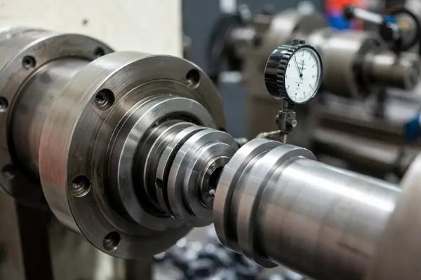
A dial indicator or suitable indicating measurement device can be used to inspect radial runout relative to a specified datum. During inspection, the required drawing datum should be established and the workpiece mounted on a suitable support or inspection fixture. The shaft is then rotated slowly while the maximum and minimum indicator readings are recorded. For long shafts with multiple journals, critical sections should be inspected according to the drawing requirements.
- Confirm the measurement datum: Select the datum journal, center hole, or other specified datum according to the drawing to prevent incorrect conclusions caused by inconsistent reference conditions.
- Define measurement locations: Inspect critical journals, bearing seats, and mating sections, adding measurement locations when necessary.
- Control support conditions: Use appropriate centers, V-blocks, or dedicated inspection fixtures to minimize the influence of workpiece weight and clamping forces.
- Record measurement data: Maintain measurement locations, maximum and minimum readings, and actual runout values for comparison with drawing tolerances.
Radial runout inspection helps identify journal positioning errors and local rotational deviations, but it does not replace roundness, straightness, or other geometric accuracy inspections. The actual inspection plan should be based on the engineering drawing.
Check Shaft Diameter, Straightness, and Surface Quality
A long shaft may have individual journal diameters within tolerance while still failing assembly requirements because of overall bending or axis displacement. Slender shafts, precision guide shafts, and transmission shafts therefore require dimensional measurement combined with an evaluation of overall geometry. Measurement should account for part length, support conditions, and temperature to prevent workpiece weight or unsuitable clamping from affecting the results.
- Outside-diameter inspection: Use outside micrometers or other suitable instruments to inspect critical journals at specified cross-sections.
- Straightness inspection: Use an appropriate measurement system according to shaft length and accuracy requirements to evaluate shaft-axis or surface straightness.
- Surface roughness inspection: Use a surface roughness tester to verify bearing fits, sealing surfaces, and sliding contact areas against specified requirements.
- Visual inspection: Confirm that the shaft surface is free from significant scratches, dents, burrs, chatter marks, and other defects that could affect assembly.
Combining dimensional, geometric, and surface-quality inspections provides a more complete evaluation of whether a long shaft meets its design and functional requirements.
How to Choose a Precision CNC Turning Manufacturer for Long Shafts?
When sourcing long shaft components, a supplier’s equipment capabilities, process experience, and inspection capabilities directly affect delivery performance. Long-shaft machining may involve more than standard external turning. It can require auxiliary supports, specialized workholding, precision machining of multiple journals, and coordination with subsequent grinding or heat treatment. For companies requiring long-term supply, selecting a CNC turning manufacturer capable of understanding drawing requirements, evaluating machining risks, and providing stable quality records can reduce purchasing risks and improve supply-chain reliability.
Evaluate Machining Capabilities Based on Shaft Geometry
Long shaft components vary significantly in total length, maximum diameter, length-to-diameter ratio, material, and machining features. Buyers should confirm whether the supplier’s machine range, tailstock and auxiliary support configuration, tooling system, and inspection capabilities are suitable for the actual order. For components containing multiple stepped journals, deep bores, threads, grooves, or precision mating sections, buyers should also confirm that the equipment and process sequence can satisfy the drawing requirements.
- Confirm machine capacity: Verify maximum machining length, diameter range, workholding conditions, and auxiliary support capabilities to prevent insufficient machine travel or workholding space.
- Review process experience: Confirm experience with slender shafts, precision transmission shafts, guide shafts, and multi-step shaft components.
- Evaluate inspection capabilities: Check whether the supplier has suitable equipment for measuring radial runout, outside diameter, straightness, and surface roughness.
- Verify batch production capabilities: Confirm stable tool management, process documentation, and batch quality traceability procedures.
A supplier with suitable equipment and process capabilities can identify bending, workholding, and precision-control risks before production and recommend an appropriate machining strategy.
Provide Complete Engineering Drawings for Accurate CNC Turning Quotes
Precision long-shaft CNC turning quotes are influenced by material costs, part dimensions, machining length, workholding requirements, auxiliary support, tooling consumption, inspection requirements, and order volume. Complete engineering documentation allows suppliers to evaluate machining difficulty, develop an appropriate process route, and reduce communication during quotation and production.
- Provide PDF engineering drawings and suitable 2D or 3D files such as STEP or STP.
- Specify material grade, blank dimensions, heat treatment condition, and surface treatment requirements.
- Clearly identify shaft diameters, total length, critical journal positions, radial runout, straightness, and relevant geometric tolerances.
- Specify prototype quantity, batch order volume, expected repeat orders, and target delivery schedule.
- Confirm first article inspection, final inspection reports, packaging, shipping, and any special quality documentation.
For long shafts with high length-to-diameter ratios, tight tolerances, or complex structures, sample validation is recommended before batch purchasing. Actual measurement results can then be used to confirm the machining process and acceptance criteria.
TiRapid provides CNC turning and precision custom machining services for a range of metals and engineering plastics. The actual machining length, diameter range, achievable tolerances, auxiliary support method, and delivery schedule for long shaft components should be evaluated according to the engineering drawing, material, geometry, and inspection requirements. Purchasing teams can submit complete drawings and expected order quantities to receive project-specific machining recommendations and quotations.