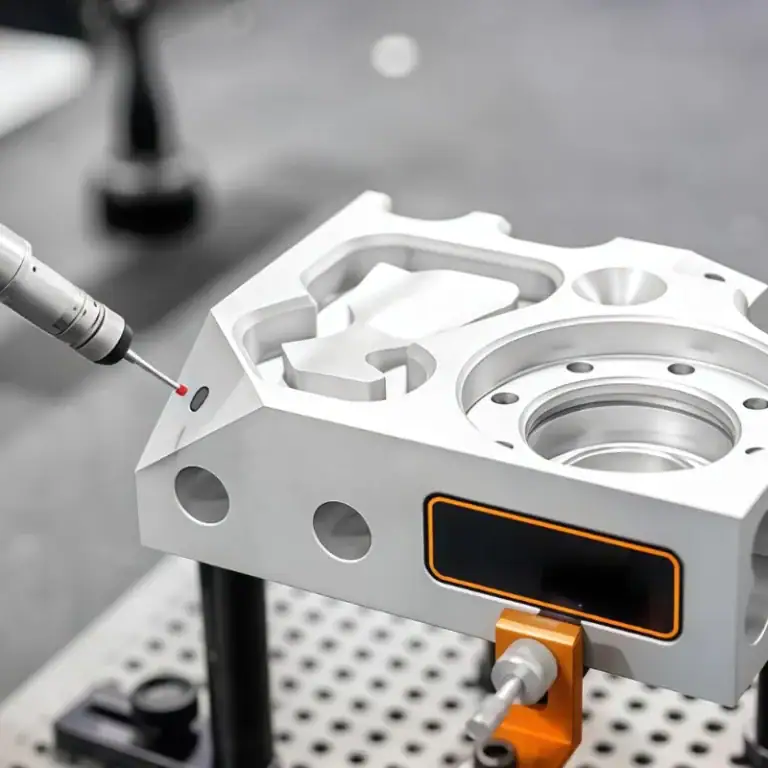
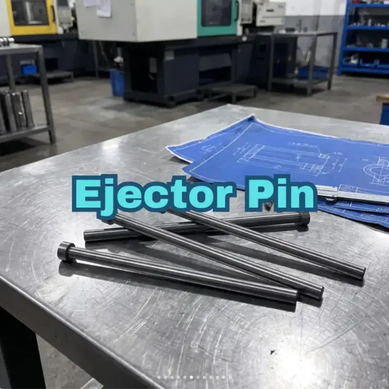
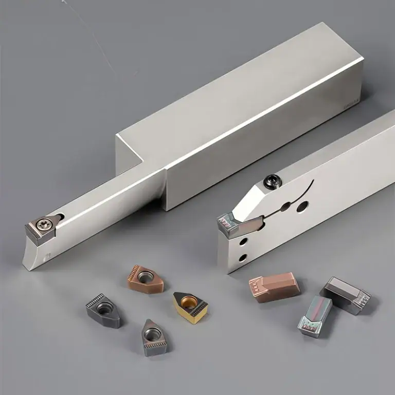
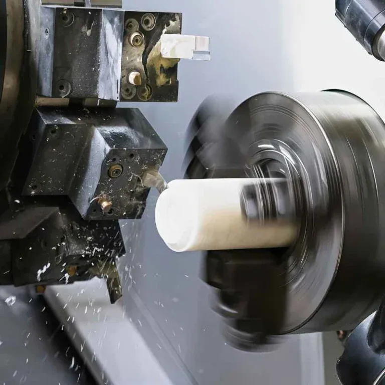
Wafer robots repeatedly perform wafer picking, placement, and transfer operations every day. The movements may look simple, but the components cannot be made with a “close enough” approach. A slight deviation in a shaft bore, an uneven mounting surface, or small differences between batches of joint components can cause motion instability, positioning errors, or additional equipment adjustment. Semiconductor equipment already demands high dimensional accuracy and stability, making components such as connecting blocks, mounting bases, shaft sleeves, and support parts especially dependent on reliable CNC machining processes for proper assembly and long-term operation.
Where Do CNC Machining Problems Commonly Occur in Wafer Robot Components?
Wafer robot components are not simply designed to look good. They need to work with motors, bearings, robotic arms, guides, and other moving components. A part may pass individual dimensional inspection and still fail to perform smoothly after being installed into the complete system. During machining, dimensions, tolerances, hole locations, and mating relationships need to be considered together to reduce assembly adjustments later.
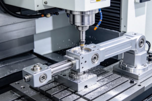
Shaft Bores and Connection Holes: Dimensional Stability Matters More Than Speed
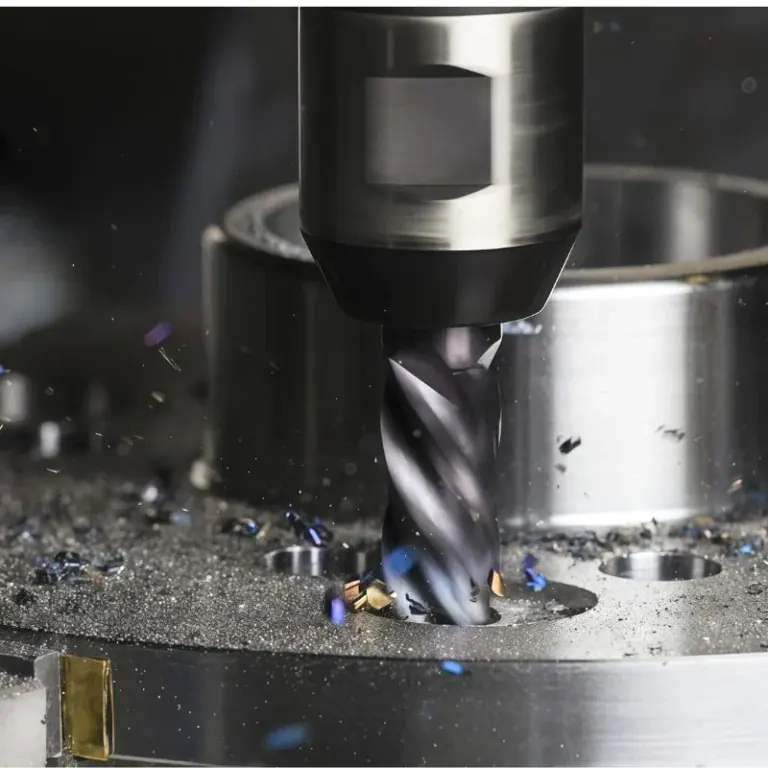
Rotating and connecting structures in wafer robots often rely on shaft bores, pin holes, or threaded holes for positioning. Excessive variation in bore diameter can result in a fit that is either too loose or too tight, while a shifted hole location can affect the relationship between adjacent components. CNC machining should use consistent datums and include in-process inspection of critical holes.
- Shaft bores require control of diameter, roundness, and their positional relationship to the relevant datum.
- For multiple mounting holes, checking only individual hole dimensions is not enough; overall hole spacing also needs to be verified.
- Threaded holes require attention to thread entry, depth, and bottom condition to avoid incomplete installation.
- Interfaces with bearings and pins need consistent dimensions so that one production batch is not too tight while another is too loose.
The real challenge with these components is often not whether they can be machined, but whether every part can maintain a similar dimensional condition. For semiconductor equipment, stable mating dimensions can significantly reduce repeated adjustments during wafer robot assembly.
Mounting Surfaces and Flatness Directly Affect Robot Motion
Mounting, connection, and locating surfaces on wafer robot components usually have a specific assembly function. Significant changes in flatness can cause tilting after installation and alter the relative position of moving components. During CNC finishing, machining allowance, tool condition, and fixturing need to be controlled rather than focusing only on achieving a smooth-looking surface.
Lightweight Structures Also Need Post-Machining Stability
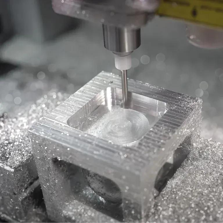
To reduce the moving load of wafer robots, some components use aluminum alloys, thin-wall structures, or localized cutouts. These designs reduce weight but can make machining more demanding. Clamping pressure, material removal sequence, and cutting loads can all influence the final dimensions.
- Material should not be removed too aggressively from cutout areas, which can suddenly reduce structural rigidity.
- Clamping force around thin-wall sections needs to be controlled to reduce springback after unclamping.
- Tool overhang should be managed when machining long slots to prevent vibration from affecting dimensions and surface quality.
- Appropriate finishing allowance should be retained so the final dimensions can be adjusted during finishing.
How Do CNC Machining Priorities Differ for Different Wafer Robot Components?
A wafer robot is made up of many different components, including connecting blocks, mounting bases, joint parts, shafts, and customized support structures. Each component performs a different function, so the critical machining areas are not always the same. Applying one identical machining approach to every part can create unnecessary dimensional variation.
Robot Mounting Bases: Control Datums and Interface Dimensions
Mounting bases typically connect the wafer robot to the main equipment structure, making hole locations, mounting surfaces, and flatness particularly important. The primary datum should be established before machining, followed by a suitable sequence for holes and external profiles. For structures with multiple interfaces, tool accessibility should also be checked in advance.
Joint Components: Hole Position and Mating Relationships Are Critical
Joint components usually interface with shafts, bearings, or other moving structures. Bore diameter, concentricity, and center distance can all affect motion performance. These components should not be inspected based on a single dimension alone. The relationship between several critical dimensions needs to be verified, especially at locations involved in repeated movement.
Supports and Connecting Blocks: Simple Structures Still Need Precision
Support components may appear simpler than joint parts, but deviations in mounting surfaces, hole locations, or overall height can still affect the position of the wafer robot. Consistent CNC positioning datums can help reduce errors caused by repeated fixturing.
| Component Type | CNC Machining Focus | Main Requirement |
| Mounting Base | Flatness, holes, datums | Stable installation |
| Joint Component | Shaft bore, concentricity, center distance | Smooth movement |
| Connecting Block | Hole position, interface dimensions | Accurate connection |
| Support Part | Height, flatness, hole spacing | Structural stability |
| Shaft Sleeve | Inner/outer diameter, roundness | Stable fit |
How Can Rework Be Reduced from Prototyping to Batch Production?
Semiconductor equipment components often go through design validation, prototype machining, and batch production. A common source of wasted time is failing to solve machining issues during prototyping and only discovering assembly problems after production has started. Confirming critical requirements early and using in-process inspection to establish a proven process can make subsequent production much more predictable.
Prototype Machining Should Go Beyond Checking a Dimensional Report
After a prototype is completed, the dimensional results are important, but actual assembly relationships also need to be considered. Mounting bases, joint components, and shaft sleeves may pass individual inspection while still showing an overly tight fit or inconsistent hole alignment when assembled together.
- Keep 2D drawings and 3D models on the same revision to prevent conflicting information.
- Identify critical shaft bores, mounting holes, and locating surfaces in advance.
- Evaluate the machining feasibility of thin walls, deep slots, and complex structures.
- Perform trial assembly when matching components are available to verify the actual fit.
- Preserve proven CNC programs and process parameters after prototype validation.
An additional inspection step during prototyping can often eliminate several rounds of rework later. For semiconductor components intended for long-term production, a stable prototype provides a much clearer foundation for subsequent manufacturing.
Critical Dimensions Need Continuous Monitoring During Batch Production
One of the biggest concerns in batch CNC machining is gradual dimensional change. Tool wear, longer machine operating times, and variations in fixturing can cause differences between the first and later parts. Checking critical dimensions throughout the process is easier to control than measuring everything only after machining is finished.
- Confirm key dimensions and hole positions after the first piece is completed.
- Measure critical holes promptly after machining rather than leaving them until final inspection.
- Monitor tool wear during extended production runs.
- Use consistent positioning and fixturing methods within the same batch whenever possible.
- Increase in-process sampling for mating dimensions that are more likely to change.
This inspection approach does not necessarily make production much more complicated, but it allows dimensional drift to be detected earlier. For larger production runs, identifying one machining change early is much easier than discovering that an entire batch needs adjustment.
Cleaning and Deburring Should Not Be Overlooked
Wafer robot components are ultimately used inside semiconductor equipment, so dimensional accuracy is not the only consideration after machining. Residue inside holes, burrs around edges, chips in slots, and scratches caused during transportation can all affect subsequent assembly. Proper deburring, cleaning, inspection, and packaging help maintain a more consistent delivery condition.
| Inspection Item | Key Inspection Content | Main Purpose |
| Dimensions | Length, thickness, outer/inner diameter | Verify basic dimensions |
| Hole Position | Hole diameter, spacing, center location | Ensure accurate assembly |
| Flatness | Mounting and locating surfaces | Maintain assembly stability |
| Fit | Shaft bores, sleeves, connection areas | Ensure smooth movement |
| Appearance | Burrs, scratches, machining marks | Maintain component condition |
| Cleanliness | Chips, particles, residue | Meet semiconductor equipment requirements |
What Practical Advantages Does Professional CNC Machining Offer for Wafer Robot Components?
For moving components such as wafer robot parts, the value of machining ultimately comes down to assembly and operating performance. A reliable CNC machining process is not simply about producing parts from drawings. It should also maintain stable dimensions between batches and support the complete process from prototype development to ongoing production.
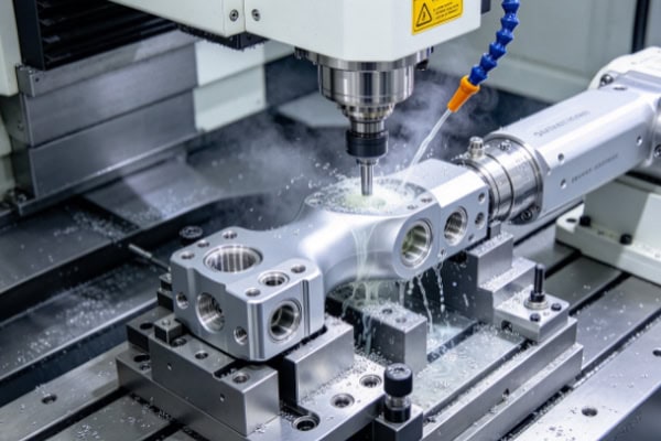
Greater Flexibility for Complex Components
CNC machining allows toolpaths, fixturing, and machining sequences to be planned according to each component’s actual structure. Multi-hole, irregular, thin-wall, and lightweight structures can all receive dedicated process adjustments. Non-standard wafer robot components can also be manufactured according to specific drawings rather than being limited by fixed specifications.
Stable Machining Accuracy Supports Repeat Production
When robot components need to be replaced regularly or supplied continuously, batch consistency becomes increasingly important. Consistent machining datums, proven toolpaths, and in-process inspection can reduce dimensional variation between batches and make subsequent assembly smoother.
Easier Transition from Prototypes to Production
Machining methods validated during the prototype stage can be carried forward into subsequent batch production. This reduces the need to develop the process again for every order and can shorten the time required to move a new component from development into stable production.
Less Assembly Adjustment and Rework
Continuous control of critical hole locations, mounting surfaces, and mating dimensions during machining can reduce problems discovered only after parts are delivered. For semiconductor equipment manufacturing, fewer component rework cycles can also reduce waiting time during equipment assembly and commissioning.
Wafer robot components may vary in size and structure, but they all depend on stable dimensions, accurate hole locations, and reliable mating relationships. For moving components used in semiconductor equipment, small machining errors can become more noticeable during assembly and operation. With a well-planned CNC machining process, in-process inspection, and batch control, components can remain more consistent from prototype development through ongoing production. TIRAPID provides CNC machining services for wafer robot and semiconductor equipment components, with customized machining based on different materials, structures, and precision requirements.